Transcription
NXP SemiconductorsApplication NoteDocument Number: AN5331Rev. 0, 09/2016Offline Flash Programmer for Kinetis K- andL-series MCUsBy: Xi YangContents1 IntroductionEffective and convenient tools for the flashprogramming are very useful in the production phaseof the product design. The traditional offlineprogramming tools are often expensive and mayinclude various limitations such as the restrictedimage size, unsupported devices, and other.Therefore, it’s valuable to provide an easy and simpleway of production flash programming for the KinetisMCUs.This application note describes how to implement aproof-of-concept offline flash programmer for nearlyall Kinetis devices. The source code and thepre-compiled binary image file are provided in theattached software. This document is intended forusers developing the production flash programminghardware, production flash programming software, ora debugger interface that supports flashprogramming. 2016 NXP B.V.12345678Introduction . 1Overview . 22.1Terms . 22.2Supported target MCUs . 3Hardware Setup .33.1Hardware platform selection.33.2Pin connections to target MCU . 3Software Setup.54.1Software structure . 54.2Flash algorithm . 6Running the Demo . 75.1Loading firmware to FRDM-K64 . 75.2Selecting flash algorithm . 75.3Adding target image file . 85.4Connecting to target. 95.5Running the demo. 9Consideration . 106.1FlexMemory partitioning and EEPROM support . 106.2Unsecure Kinetis . 106.3Target image file. 11References . 11Revision History . 11
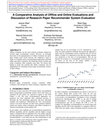
Overview2 OverviewThis document describes how to implement a proof-of-concept offline flash programmer for the KinetisMCUs and the low-cost methods for the production flash programming. The key features include: NXP FRDM-K64 as the hardware platform. Support for most of the Kinetis K and Kinetis L series MCUs. Support for the program data flash. The image binary file and the flash algorithm configuration file stored on the SD card.Figure 1. Offline programmer overviewBefore reading this document, see Production Flash Programming Best Practices for Kinetis K- and Lseries MCUs (document AN4835) to gain knowledge of the SWD debug and flash programming for theKinetis series.2.1 TermsThis table summarizes the meaning of the terms used in this document:Table 1. TermsTermMeaningOffline programmerTarget MCUThe tools that can store the target image file and load the file into the target MCU’s internalprogram flash or data flash.The MCU on the target board to download the image to.The target MCU’s reset pin.TRSTTarget image fileThe binary file to load into the target MCU.Offline Flash Programmer for Kinetis K- and L-series MCUs, Rev. 0, 09/20162NXP Semiconductors
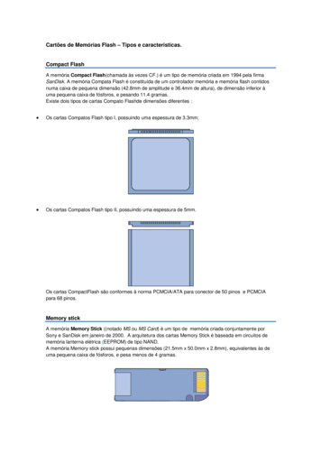
Hardware Setup2.2 Supported target MCUsThe demo software attached to this document supports these target MCUs: Kinetis K0/1/2/3/4/5/6/7/8/x MCUs. Kinetis KL1/2x MCUs.3 Hardware Setup3.1 Hardware platform selectionThe NXP Freedom development platform FRDM-K64 board is selected as the offline programmerhardware platform. This platform is popular among the developers. This is the list of the on-boardperipherals used in this demo: SD card socket—used to store the target image and configuration files. GPIO pin socket—used to lead out the SWDIO/SWDCLK and TRST pins. Tricolored LED—used as the system status indicator. OpenSDA—used as the debugger and flash downloader for the K64; it can be also used as theUSB-UART bridge.3.2 Pin connections to target MCUFour wires need to connect the offline programmer to the target MCU, as shown in this table:Table 2. Target pin connectionNameFRDM-K64TargetCommentsSWD DIOPTB3 (J4-4)SWD DIOConnected to the target MCU’s SWD DIO pinSWD CLKPTB2 (J4-2)SWD CLKConnected to the target MCU’s SWD CLK pinTRSTPTB10 (J4-6)RESETGNDGND (J3-14)GNDConnected to the target MCU’s reset pinGND must be connectedBesides the connections, make sure that: The target MCU must be powered before connecting the SWD and TRST pins. The target MCU’s reset pin signal is clean and is not controlled by any other external signal(another debugger, key button). If you use the NXP Freedom and Tower System modular development platform boards, cut theconnection between the target MCU and the on-board OpenSDA (SWD IO, SWD CLK, andTRST). You can do this in any of these ways:— If the FRDM/TWR board has a hardware jumper/0- resistor, just change the jumpersetting or remove the resistor. For example; on the FRDM-K22 board, remove R58 anddisconnect J13 and J10:Offline Flash Programmer for Kinetis K- and L-series MCUs, Rev. 0, 09/2016NXP Semiconductors3
Hardware SetupFigure 2. Disconnecting OpenSDA from target MCU— If the FRDM/TWR board does not have the hardware jumper/resistor, erase theOpenSDA’s firmware or put the OpenSDA into the bootloader mode. This sets theOpenSDA’s target debug pins into the input states.Offline Flash Programmer for Kinetis K- and L-series MCUs, Rev. 0, 09/20164NXP Semiconductors
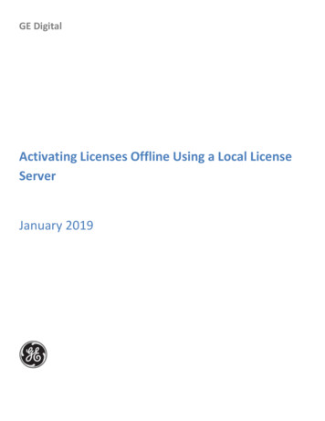
Software SetupThis figure shows a typical connection of the offline programmer (the target MCU board is theFRDM-KL26):Figure 3. Hardware connection4 Software Setup4.1 Software structureThe offline programmer software is developed using KSDK2.0. It can be divided into several functionalmodules: SWD protocol implementation and DAP access—these codes are ported from the CMSIS-DAPsource code (see github.com/mbedmicro/CMSIS-DAP). Flash algorithm—includes the target flash programming code and the WDOG disable sequence.This position-independent code is downloaded to the target RAM and executed by the targetMCU when initializing and programming the target flash.Offline Flash Programmer for Kinetis K- and L-series MCUs, Rev. 0, 09/2016NXP Semiconductors5
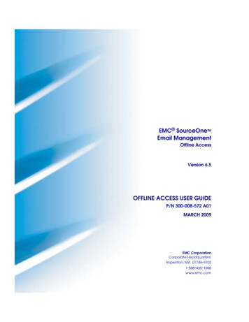
Software Setup The SD card driver, FAT32 driver code, and all other chip peripheral drivers, startup file, andheader files are reused from the SDK2.0\frdmk64f\driver examples\sdcard fatfs demo.The overall software workflow is shown in this figure:SD card initialization andmount FAT32 filesystemRead setting.ini get flashtype and WDOG typeCheck target image fileintegrityConnect target via DAP,set target into debugmodeNDownload flashAlgorithm to targetOutput log andhalt systemYProgram target flash thenreset targetFigure 4. Software workflow4.2 Flash algorithmThe common flash algorithm that supports most MCUs from the Kinetis K and KL series is needed forthe offline programmer. You must have control over the target MCU’s core to run the flash algorithm.Therefore, disable the target MCU’s WDOG. There are some differences between the Kinetis seriesWDOG and flash modules: WDOG disable sequence—most Kinetis series use four different types of WDOG modules, asshown in the following table.Offline Flash Programmer for Kinetis K- and L-series MCUs, Rev. 0, 09/20166NXP Semiconductors
Running the DemoTable 3. WDOG type OptionNameDescriptionExamples1WDOG88-bit WDOG moduleKE0x2WDOG1616-bit WDOG moduleMost of the Kinetis K/V/M seriesMCUs3WDOG3232-bit WDOG moduleKE1x and KL284COPWDOG integrated in theSIM module (called COP)Most of the Kinetis KL series MCUsFlash sector size—program flash sector size. If the target MCU has the FlexNVM, the data flashsector size is also included. In most parts, the data flash size and the program flash size are thesame. The flash sector size can be either 512, 1024, 2048, or 4096 bytes.Flash program command—after a flash sector (or the entire flash) is erased, the programmingcan start. There are three different flash-programming commands:— Program section.— Program longword (32-bit, PGM4).— Program phrase (64-bit, PGM8).Although the program section command is the fastest way to program the flash, it is only supported oncertain devices. All devices support either the PGM4 command or the PGM8 command, but not both. Tomaintain compatibility, the demo uses either the PGM4 or PGM8 commands to program the flash.Different combinations of the WDOG type, flash sector size, and flash program command can beapplied to one or many specific target MCUs. In the source code, this combination is pre-defined as theflash option. See the following section for more information.5 Running the Demo5.1 Loading firmware to FRDM-K64Load the firmware provided in the attached software package into the K64. It’s the same as with allSDK2.0 demo applications.5.2 Selecting flash algorithmSelect the correct target MCU flash algorithm and the WDOG disable sequence. You can do this bymodifying (creating) the setting.ini file on the SD card: Create/modify the setting.ini file in the root directory of the SD card. Type this into the file:[TARGET]FLASH OPTION XOffline Flash Programmer for Kinetis K- and L-series MCUs, Rev. 0, 09/2016NXP Semiconductors7
Running the DemoFigure 5. Flash algorithm configuration filewhere X is the flash option.The flash options are summarized in this table:Table 4. Flash algorithm izecommand0WDOG160x400520002048PGM4KS22FN256, 7WDOG160x400520004096PGM4MK8xFN256ExamplesFor the COP, the WDOG base refers to the SIM module base address. If you don’t find the target MCUin the “Examples” column, just find a similar part where the WDOG, sector size, and program commandare all the same as on the target MCU.5.3 Adding target image fileThe offline programmer can accept the raw binary files only in the current version. These two imagefiles must be copied into the SD card root directory with fixed file names: PIMAGE.BIN—program flash binary image. DIMAGE.BIN—data flash binary image.Figure 6. SD card root directory screenshotThe .bin files can be generated by the IDE post-compile command. If target MCU does not have a dataflash or there is no need to program the data flash, just remove the DIMAGE.BIN file.Offline Flash Programmer for Kinetis K- and L-series MCUs, Rev. 0, 09/20168NXP Semiconductors
Running the DemoPut the SD card into the FRDM-K64’s SD socket, connect the OpenSDA’s USB to the PC, open theserial terminal with 115200, N8N1 and power on the board.5.4 Connecting to targetConnect the SWDIO/SWDCLK/TRST and GND signals to the target MCU. Power the target board asdescribed in Section 3, “Hardware Setup”.5.5 Running the demoPress the reset pin on the FRDM-K64 to start the demo and the on-board three-color LED indicates thesystem status. When running the demo for the first time, look at the PC terminal log to debug and tracethe errors.The blue LED lights and the system halts if one of these conditions occurs: The SD card initialization failed. The FAT32 file system mount failed. No target image file (wrong file name/path) or configuration file detected.The red LED lights and the system halts if one of these conditions occurs: Failed to connect to the target MCU. Failed to download the flash-programming algorithm into the target RAM. This can be caused bya wrong flash algorithm option selection, a secured chip (mass erase is disabled), or a hardwareconnection issue. Failed to program the image file data into the target flash.The green LED blinks if one of these conditions occurs: The offline programmer is programming the target flash. The green LED blinks at a frequency of3 20 Hz, according to the SWD clock cycle and the target flash sector size. The offline programmer finishes all tasks successfully. The green LED blinks at a frequency of1 Hz to indicate that all tasks completed successfully and you can move to the next target andpress the FRDM-K64’s reset pin to start a new load task.Offline Flash Programmer for Kinetis K- and L-series MCUs, Rev. 0, 09/2016NXP Semiconductors9
ConsiderationThis figure shows the log information when the load into the target MCU is successful:Figure 7. Output log6 Consideration6.1 FlexMemory partitioning and EEPROM supportUse the flash program partition command (PGMPART) to set up the memory partitioning and configurethe EEPROM for use. After the EEPROM is configured and (optionally) loaded, the data can beprogrammed into the remaining data flash. Be careful when programming the data flash and do notattempt to program the area which is already initialized as the EEPROM. See the flash section in thechip reference manual for more information about the program partition.6.2 Unsecure KinetisThe source code provided with this document contains unlocked Kinetis sequences. The secure Kinetiscan’t accept most flash commands, such as the erase sector or program flash commands. If a secureKinetis is detected, the offline programmer tries to unlock the target MCU (by performing a mass eraseand deleting all data) without a notice. If the target MCU Mass Erase Enabled bit 0, the offlineprogrammer can’t perform the mass erase operation and the system halts.Offline Flash Programmer for Kinetis K- and L-series MCUs, Rev. 0, 09/201610NXP Semiconductors
Revision History6.3 Target image fileMake sure that the target image files are correct. If not, the loading process may secure the target MCU.The demo software does not check the file size or the target MCU flash size. If the target image file isbigger than the target MCU flash, a loading error occurs and the system halts.7 References1. Production Flash Programming Best Practices for Kinetis K- and L-series MCUs(document AN4835)2. ARM CoreSight Components Technical Reference Manual available at www.arm.com3. KINETIS-SDK: Software Development Kit for Kinetis MCUs available at www.nxp.com/ksdk8 Revision HistoryThis table summarizes the changes done to this document since the initial release:Table 5. Revision historyRevision numberDateSubstantive changes009/2016Initial release.Offline Flash Programmer for Kinetis K- and L-series MCUs, Rev. 0, 09/2016NXP Semiconductors11
How to Reach Us:Home Page:nxp.comWeb Support:nxp.com/supportInformation in this document is provided solely to enable system and softwareimplementers to use NXP products. There are no express or implied copyright licensesgranted hereunder to design or fabricate any integrated circuits based on theinformation in this document. NXP reserves the right to make changes without furthernotice to any products herein.NXP makes no warranty, representation, or guarantee regarding the suitability of itsproducts for any particular purpose, nor does NXP assume any liability arising out of theapplication or use of any product or circuit, and specifically disclaims any and allliability, including without limitation consequential or incidental damages. “Typical”parameters that may be provided in NXP data sheets and/or specifications can and dovary in different applications, and actual performance may vary over time. All operatingparameters, including “typicals,” must be validated for each customer application bycustomer’s technical experts. NXP does not convey any license under its patent rightsnor the rights of others. NXP sells products pursuant to standard terms and conditionsof sale, which can be found at the following address:nxp.com/SalesTermsandConditionsNXP, the NXP logo, NXP SECURE CONNECTIONS FOR A SMARTER WORLD,Freescale, the Freescale logo, Kinetis, Tower, and Freedom are trademarks of NXPB.V. All other product or service names are the property of their respective owners.ARM, the ARM Powered logo, Cortex, and CoreSight are registered trademarks of ARMLimited (or its subsidiaries) in the EU and/or elsewhere. All rights reserved. 2016 NXP B.V.Document Number: AN5331Rev. 009/2016
proof-of-concept offline flash programmer for nearly all Kinetis devices. The source code and the pre-compiled binary image file are provided in the attached software. This document is intended for users developing the production flash programming hardware, production flash programming software, or a debugger interface that supports flash