Transcription
ATS Installation Setup and MaintenanceP/N SG07230018REVISION DDes Moines, IA (800) 333‐7411Burnsville, MN (800) 289‐1330Mundelein, IL (888) 905‐7411THIS DRAWING IS COPYRIGHTED ANDIS THE PROPERTY OF CERTIFIED POWER INC.Bridgeton, MO (800) 999‐7411Perrysburg, OH (800) 374‐7411
Freedom ATSUsers Manual: SG07230018User Manual Freedom ATSFREEDOM ATS USERS GUIDEMOBILE DATA COLLECTION DEVICEPART# SG07040073(Wi‐Fi, GPS Receiver.)PART# SG07040074(non‐Wi‐Fi, no GPS Receiver)PART# SG07040078(non‐Wi‐Fi, GPS Receiver.)PART# SG07040087(non‐Wi‐Fi, No GPS Receiver, No Sd Card)Revision 08/16/20108/28/2012DESCRIPTIONCCNFIRST DRAFT RELEASEPROD. UPDATESPROD. UPDATESPROD. UPDATESPROD. UPDATES593PurposeA. This manual is a guide to assist in the setup and management of the Freedom ATS(Advanced Tracking System). This manual leads the user through a step‐by‐step setupprocess for several given application examples presented below.B. Setup is simple and is achieved using the built in web server configuration tool includedwith each unit. A laptop with a 10/100 network port and the provided cable is all that isrequired for fast configuration.Certified Power Inc. 970 Campus Dr. Mundelein, Il 60060 1‐888‐516‐5245Page 2
Freedom ATSUsers Manual: SG07230018ContentsRevision history . 2Purpose . 2Product Description . 5Supported Applications . 7Freedom ATS (User) panel description . 9Installation of Equipment . 11Mounting dimensions . 12Wiring and Cable Layout . 13Optional Wiring Switches and Output Devices/Main Power . 13Setup and Configuration . 14Accessing the Web Server . 14Admin Access Login. 16Main menus . 16Applying Changes . 18Save a Configuration File . 19Removing the SD card . 19View a saved file . 20Delete a saved file . 20Restoring a saved file . 20Setting Time and Date. 21Manual Data Transfer Application Guide (Removable Data storage) . 22Equipment required. . 22Summary of hardware installation steps . 22Configure an Application using Manual Data transfer. 23General Configuration & Setup . 23The Server Interface . 26Maintenance. . 27Cellular Modem or LMU Application Guide (Cellular data transfer): . 28Equipment required. . 29Summary of hardware installation steps . 29Configure a Cellular or LMU Application . 29Certified Power Inc. 970 Campus Dr. Mundelein, Il 60060 1‐888‐516‐5245Page 3
Freedom ATSUsers Manual: SG07230018General Configuration & Setup . 29The Server Interface . 33Modem Configuration and setup . 35Maintenance . 35Drive‐by Download Application Guide (Wi‐Fi) . 36Equipment required. . 36Summary of hardware installation steps . 36Configure a Wi‐Fi Drive‐by Application . 37General Configuration & Setup . 37The Server Interface . 40Wireless Configuration. . 42Network Configuration . 43Maintenance . 43ATS mini . 44Equipment required. . 44Summary of hardware installation steps . 44Configure an Application using the ATS Mini. 45General Configuration & Setup . 45The Server Interface . 48Input Configuration . 49General Setup of inputs . 49Counter Input Configuration . 51Counter Input Calibration (Viewing Counts using the built in Pulse Counter) . 51Diagnostic tools/Troubleshooting Assistance . 52Diagnostic LED’s. . 52GPS Viewer . 53Event/Error log . 54Modem status . 55Updating firmware/Loading defaults/Restoring your settings . 56Deleting a Configuration (Restoring defaults) . 58Wi‐Fi Setup & Security (Glossary of terms). 59Certified Power Inc. 970 Campus Dr. Mundelein, Il 60060 1‐888‐516‐5245Page 4
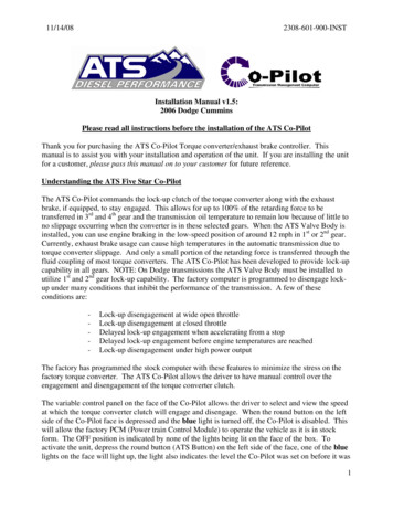
Freedom ATSUsers Manual: SG07230018What’s includedA. The illustration below details the optional and included hardware with each Freedom ATS unit.(2X) 2 dBi DI-POLEANNTENNASTANDARD POWERHARNESSP# SG07050880GPS WINDOWMOUNT ANTENNAP# SG07040076I/O HARNESS6-WIRE(Optional)P# SG070508798-WIREP# SG07050878SD MEMORY CARDPART# SG07040081DDyyyyyyProduct DescriptionThe Freedom ATS is a simple to apply Mobile Data Management & Collection Device. The primary advantage of theATS is easy installation and setup. A Cellular Service is not required for 2 out of 4 typical ATS Setups shown here.Out of the Box standard features include a removable SD memory card for seasonal data collection, or built in on‐board Wi‐Fi (Drive‐by‐Download). The standard unit also requires NO additional software to begin managementwith its built in web configuration tool, setup and maintenance couldn’t be more convenient. If the ATS is on anetwork or connected to your laptop using the provided cables, all setup and configuration can be done with anyPC running a web browser such as Internet Explorer , Firefox , or Opera . The WLAN (Wi‐Fi) transceiver includesall the latest authentication methods and also the latest levels of 802.11 A/B/G/I, encryption. The Freedom ATS iscompatible with the model GL400, Freedom 2 or ACS spreader control units. The ATS can be used with any otherApplication that utilizes a compliant standard RS‐232 serial port. The ATS can be used for many applications thatutilize its standard features including asset tracking or remote data acquisition, storage and transmission.GPS Receiver (optional), The GPS signal contains GMT time, latitude and longitudinal data and other geometricdata used to calculate velocity and altitude. Snap‐shots of current GPS data along with a time stamp and any otherdata such as from a Salt Spreader controller are stored together in sequential records. If using the GPS receiver thereal‐time clock is based on GMT (or UTC) time received from the satellite. If no GPS receiver is installed then data istime stamped based on the set time of the internal real‐time clock value.Wi‐Fi, (Wireless LAN) (optional), This Wireless IP Gateway option is one of two wireless options used for datatransfer and equipment configuration and maintenance. Wireless LAN is a good cost economical alternative to aCellular data or the complications of using a Digital radio network. The latest levels of authentication andencryption are available for the Wireless LAN (Wi‐Fi). The downside of Wireless LAN offers no real‐time Datatransfer such as with Cellular and has limited signal range (120 to 900ft.)Certified Power Inc. 970 Campus Dr. Mundelein, Il 60060 1‐888‐516‐5245Page 5
Freedom ATSUsers Manual: SG0723001810/100 Ethernet, This is a wired LAN port. This port is typically used for web services especially during initial setupof the ATS device when it’s fresh out of the box. Web based configuration and troubleshooting are done using thisconnection. Web services can be accessed over the Wi‐Fi port as well, once the port configuration has been setup.The wired 10/100 Ethernet port is programmed from the factory with a static IP address of 192.168.11.120. Useyour computer and the provided cross‐over network cable P#SG07050754 or attach the unit to your network withany standard network cable. Use your PC’s Internet Explorer , Mozilla Firefox or Opera internet browser tocomplete setup and configuration. See the section about accessing the web server below.Digital inputs (Not used on ATSmini), ANY battery level or switch to ground signal can be wired into the digitalinputs. The inputs are rated for voltages from ground level to 28volts. The inputs also have integrated noiseimmunity and surge protection. Inputs can be configured to activate by switching to ground or switching to power.Use the on‐board web configuration tool to program input options. Some application examples are listed below.Inputs 1‐8 can be configured as counters up to 300 hertz. Input 8 can be used as a High Speed counter to 5 Khz. Plow position switch 3‐wire Proximity switch Body Up detect switch Way‐point input switch Hall /Motor Sensor inputBattery level outputs (4) (Not used on ATSmini), Hi‐level output drive capability. These outputs can switch peakloads up to 6 amps continuous. These outputs can be used for basic I/O requirements; Reverse polarity, thermal,and short circuit protection make these outputs useable for any resistive or inductive load applications.Modem serial port, This physical DB‐9 connector style RS‐232 serial port is intended for connection of RS‐232cellular modem using RS‐232 level compliant serial communication. The port contains all control lines available forfull modem control. Baud rates and all setup parameters are accessible through the web based configuration tool.Real‐time cellular data is transmitted out of this port when a cellular modem is attached.Spreader Serial port, This physical DB‐9 connector style RS‐232 serial port is intended for connection to MaterialSpreaders or other on and off‐road equipment controllers with a serial port. This port is a 3‐wire port TX,RX, andGround connection. This data connection links the Salt spreader or ON and Off road equipment to the ATS systemand allows materials data to be captured and stored on the ATS unit for retrieval through any installation optiondefined in this document.Road‐Watch SS (RS‐485) (Not used on ATSmini), This half‐duplex RS‐485 serial ports default usage has itconfigured for the Commercial Vehicle Systems (Sprague devices) Road‐Watch communications. The port autodetects the Road‐Watch SS sensor when it is plugged in. Note: This port is Not active when the spreader interfaceis configured for a Freedom ACS.SD Memory card (Not used on ATSmini), The Industrial rated removable FAT file system drive is MicrosoftWindows compatible and is the default storage location for all data records for your application. It isrecommended that the SD memory card be installed for most applications. Those applications include manual datatransfer, real‐time cellular data transfer and Drive‐by‐download. Limited data collection can be done without theSD card installed but the file size is limited and is not a suitable substitute for the SD card.Certified Power Inc. 970 Campus Dr. Mundelein, Il 60060 1‐888‐516‐5245Page 6
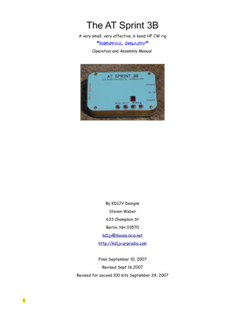
Freedom ATSUsers Manual: SG07230018Supported ApplicationsBelow are some rudimentary diagrams of some supported applications. This manual is intended to help the usersetup or make adjustments to their application. It is likely your application could use features that encompassmultiple examples below.Manual Data Transfer Application (Removable data storage SD card)LAPTOP ORDESKTOPGPS SATELLITESSDUSB TO SD CARDADAPTORVEHICLE EQUIPMENTGPS ANTENNAFREEDOM ATSSERIALCABLESALTSPREADERCONTROLI/O DEVICES: SWITCHES,RELAYS, HYDRAULICVALVE COILSCellular Modem Application (Real‐Time Cellular Data transfer)GPS SATELLITESINTERNETCELL TOWERVEHICLE EQUIPMENTCELLANTENNACELLULARMODEMSERIALCABLEGPS ANTENNAFREEDOM ATSSERIALCABLEI/O DEVICES: SWITCHES,RELAYS, HYDRAULICVALVE ified Power Inc. 970 Campus Dr. Mundelein, Il 60060 1‐888‐516‐5245Page 7
Freedom ATSUsers Manual: SG07230018Drive‐by Download Application (Wi‐Fi)CENTRAL OFFICEWI-FI ANTENNASGPS SATELLITESLIMITED RANGEACCESS POINTVEHICLE EQUIPMENTCOMPUTERCLIENTDATABASEWI-FI ANTENNASGPS ANTENNAFREEDOM ATSSERIALCABLEI/O DEVICES: SWITCHES,RELAYS, HYDRAULICVALVE COILSSALTSPREADERCONTROLThe ATSmini, a low Cost Safe and reliable Solution for data collection gateway between Salt Spreaders and LMU orModem.VEHICLE ABLESALTSPREADERCONTROLCertified Power Inc. 970 Campus Dr. Mundelein, Il 60060 1‐888‐516‐5245Page 8
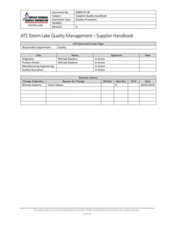
Freedom ATSUsers Manual: SG07230018Freedom ATS (User) panel descriptionA. WLAN (WIFI). Wireless LAN network connection. The panel connector is SMA MALE (x2) type.B. Wired 10/100. Ethernet network. The wired port is a standard feature on all units.C. System Status LED’s. Standard to all ATS units are status LED’s displaying real‐time diagnosticcodes. See diagnostics and troubleshooting section at the end of this manual.D. SD CARD. Standard to ALL ATS units. Removable memory card is used as primary data storage. Itis highly recommended this card always be installed into the ATS unit when the ATS unit ispowered on.E. GPS Antenna. Attached window mount GPS antenna to this connector. The panel connector isSMA FEMALE type.USER PANELWIRED 10/100WLAN ANTENNAGPS ANTENNANETWORK(WIFI) PRIMARY WLAN ANTENNACONNECTION(WIFI) SECONDARYSD MEMORYCARDSYSTEM STATUSLEDS(WIRED 10/100 NETWORK)LINK/ACTIVITY LED'SCertified Power Inc. 970 Campus Dr. Mundelein, Il 60060 1‐888‐516‐5245Page 9
Freedom ATSUsers Manual: SG07230018Freedom ATS (Interface) panelA. Digital inputs. Attach Toggle switch, Proximity switch, Door pin switch, or Hall Motor Sensor tothese 8 inputs. Both Battery and Ground signals are compatible. A BAT and Ground is availableat the 10‐pin connector. Do not attach the ground to chassis if it can be avoided to prevent extraground loops. The input current is 10mA. At 13.8volts when pulled to ground and 5mA whenconfigured for switch to power. Configure inputs through the Webpage menu “InputConfiguration”.B. Digital outputs. Battery level driven outputs. Drive up to 4 separate loads simultaneously. Shortcircuit and thermally protected. These can be custom configured for your application.C. Modem serial port (RS‐232). DB‐9, RS‐232 compliant full‐modem control port.D. Spreader serial port (RS‐232). Host type (Male) Db‐9 RS‐232 compliant 3‐wire TX,RX, & Ground.E. Battery and Ground connector. Wire into a minimum 5 amp accessory ignition switched circuit.Attach ground lead to a good chassis ground connection.F. Road‐Watch SS connection. Connect the Sprague devices “Road watch” air and road surfacetemperature sensor here. Use s Turk M8 6P style connector. Road‐watch sensor part# 849‐0242‐000INTERFACE PANEL1-IN12-IN23-IN34-IN45-BATT 6-IN57-IN68-IN79-IN810-GND.10 9 8 7 65 4 3 2 11-LOAD12-LOAD23-LOAD36 5 43 2 14-LOAD45-GND.6-GND.2 1-BATT. SUPPLY IN1 2-GROUND INFULL MODEMPORT (RS-232)ROAD-WATCH SS (RS-485)CONNECTIONSPREADERPORT (RS-232)Certified Power Inc. 970 Campus Dr. Mundelein, Il 60060 1‐888‐516‐5245Page 10
Freedom ATSUsers Manual: SG07230018Installation of EquipmentEquipment required. Freedom ATS unit: SG07040073 (With Wi‐Fi and GPS), SG07040074 (No Wi‐Fi and without GPS)or SG07040078 (No Wi‐Fi but with GPS), or SG07040087 (No Wi‐fi, GPS or SD Card installed) ATS Server Software part# SGS00300100003 Optional ATS Database Reporting Software SGS00300100002 Basic tools to mount the ATS device and route and splice the wire harness into the vehicle.Mount the ATS unit1. Securely mount ATS device inside the vehicles interior cab. The User panel would typically be oriented foreasy access to the LED indicators, 10/100 port and SD Card slot.Attach Wiring and cables2. ‐Attach fused primary Battery and ground wires.3. ‐Attach serial cables provided to spreader controller. Use the INSTALLATION and WIRING AND CABLELAYOUT pictorials as a guide.Install GPS antenna (If GPS RCVR installed)1.‐Properly install the GPS antenna as described in the installation steps below.a.b.c.The sealed weather‐proof GPS antenna has an integral magnet and ideally should be locatedabove the vehicle with a clear view of the sky.Avoid overhead metal objects that will interfere with satellite signals.Avoid mounting areas that have excessive heat, vibration or locations close to other antenna’s orsources of magnetic fields such as electric motors or high current or high voltage wiring such asstrobe lights.GPS ANTENNAGPS ANTENNANON-OBSTRUCTEDVIEW OF SKYCertified Power Inc. 970 Campus Dr. Mundelein, Il 60060 1‐888‐516‐5245Page 11
Freedom ATSUsers Manual: SG07230018Mounting dimensionsMounting of the ATS unit. (not to scale) Recommended location for mounting is the back interior wall of the vehicle cab,trunk or any location where the antennas will not be damaged. (remoteantenna is always an option for trunk mounted units)Certified Power Inc. 970 Campus Dr. Mundelein, Il 60060 1‐888‐516‐5245Page 12
Freedom ATSUsers Manual: SG07230018Wiring and Cable Layout21CHOOSECOMPATIBLECABLE(SEE ADDEMDUM FORTESTED MODEMS)12GROUND IN.POWER HARNESSPART# SG07050880BATTERY IN.ROADWATCH PART#849-0242-000ATTACH TO 5 AMPMINIMUM FUSEPROTECTEDIGNITION CIRCUITMULTI-TECH MODEMHARNESS PART#SG07050753CELLULAR MODEMOR RADIOACS SERIAL CABLEPART# SG07050647ATTACH TO BARE METALEXPOSED CHASSISGL400/FREEDOM 2SERIAL CABLE PART#SG07050056GL400 SPREADEROptional Wiring Switches and Output Devices/Main PowerINPUTS SWITCHES AND POSSIBLE USESOF OUTPUT DEVICES SHOWN.POWER HARNESS6 5 43 2 110 9 8 7 65 4 3 2 1INPUTS5678910OUTPUTS234OUT-41OUT-3BATT. S PART#SG0705087956GROUND4GROUND3OUT-22OUT-11HARNESS PART#SG0705087821IN-81IN-7IN-6 lampIN-3 IN-5-GROUND IN.IN-42BATTERY IN.POWER HARNESSPART# SG07050880ATTACH TO BARE METALEXPOSED CHASSIS. KEEPGROUND WIRE AS SHORTAS POSSIBLEIN-2solenoid- 3A. AGC FASTACT ONLY BUZZER-Certified Power Inc. 970 Campus Dr. Mundelein, Il 60060 1‐888‐516‐5245REDrelayATTACH TO 5 TO10 AMP FUSEPROTECTEDCIRCUITPage 13
Freedom ATSUsers Manual: SG07230018Setup and Configuration Attach your computer configured with a static IP address to the wired Ethernet connection on the side ofthe ATS device using the provided cross‐over cable P#SG07050754.LAPTOP ORDESKTOPFREEDOM ATS SERVER UNITCABLE PART# SG07050754Accessing the Web ServerConnecting for the first time to the ATS configuration utility (Web browser utility)1.2.Apply Power to all devices (Spreader, ATS system, and Spreader control system)The green LINK, and intermittently the yellow ACTIVITY LED’s should become active if there’s a goodconnection over the Ethernet cable from your laptop to the ATS device.-USER PANELFREEDOM ATSYELLOWACTIVITYLIGHTGREENLINK LIGHTCertified Power Inc. 970 Campus Dr. Mundelein, Il 60060 1‐888‐516‐5245Page 14
Freedom ATSUsers Manual: SG07230018Open your Internet Browser to gain basic access to the Home Page (Setup and Configuration cont.)1.First time users can use their internet browser to navigate to the default static address exactly as shownbelow in the upper magnified view http://192.168.11.120.2.The Home page displays basic information about the ATS system. Product name, Freedom ATS Firmware version, This number tracks what software release currently resides on the device. Internal Db Version, The version of the internal database. This usually changes when thefirmware version changes. Build Date, Tells you build/release date of the software running on this system. BSP firmware load date, The last date the rom.bin file was loaded. Application firmware load date, The last time the image.bin file was loaded. Backup firmware load date, The last time the backup.bin file was loaded. IP Address (Ethernet or Wireless), The current IP address assigned to this ATS unit. Ethernet/Wireless MAC Address, A fixed unique address associated with the network port. Up Time, Continuous Run‐Time since last boot. Total Run Time, Total cumulative run time since the last configuration change.Without logging‐in there is access to a few basic menus for diagnostic purposes. Home, Always brings you back to Home page. GPS Viewer, GPS data can be viewed without logging in. Event log, View Event log (Errors and Status messages) Reboot, Reboot the ATS unit.The default factory static IP address to navigate to through your internet browser is 192.168.11.120 andis used for the wired Ethernet port located on the side of the ATS unit. It is recommended to leave thisport configured as a static address so it can be easily accessed.3.4.Certified Power Inc. 970 Campus Dr. Mundelein, Il 60060 1‐888‐516‐5245Page 15
Freedom ATSUsers Manual: SG07230018Admin Access Login1.Click onlogo to gain access to login dialog box. You must log‐in as Administrator tomake configuration changes to the ATS unit. The user name and password are case sensitive and must beentered exactly as shown below. The administrator login name is “CP Service” The password is “847‐573‐3800”Main menus2.The HOME menu screen will appear after a successful login.3.If you have a problem logging in you will see the “page Access denied”. (see next page)Certified Power Inc. 970 Campus Dr. Mundelein, Il 60060 1‐888‐516‐5245Page 16
Freedom ATS Users Manual: SG07230018Page Access Denied screen shown after failed login.Menus and sub‐menus (Setup and Configuration cont.)Purpose: The menu tree always appears on the left side of the web page. You can click on any item visibleon the tree. The menu seen below is available after successfully logging in as an administrator. Whenchanging items on a particular page be sure to “APPLY” any changes before leaving the page or thechanges will be thrown away. Home, Clicking home always brings you back to the Home screen (The first screen viewed aftersuccessfully connecting to the ATS web server). GPS Viewer, GPS data can be viewed. Note: ATS must have a GPS installed and configured. Event/(error) Log, If “Verbose” logging is enabled you can view STATUS and ERROR logging here. Reboot, After completing changes on any webpage it is necessary to reboot to have changes takeeffect. Network Configuration, Change settings relating to the physical setup of network connections(TCP/IP). File Management, View current database files in flash memory or see data records or config filessaved to the FAT file system located on the SD memory card. It is also possible to select a newdatabase file (ATSconfig.bin) if one is has been saved. Install Options, The application and hardware setup occurs on this screen. Save Configuration, Creates 2 files including a binary file on the SD memory card that contains allconfiguration data useful for restoring system configuration on a new or existing ATS unit. Thesecond file is a text file that can be read directly using Microsoft WordPad .Menus and sub‐menus continued (on next page) (Setup and Configuration cont.)Certified Power Inc. 970 Campus Dr. Mundelein, Il 60060 1‐888‐516‐5245Page 17
Freedom ATSUsers Manual: SG07230018(Setup and Configuration cont.) Date and Time, View and change the current time. Auto set if GPS checked in “Install options”.Upload Firmware, If it’s necessary to upgrade the firmware (functional code) then use thisscreen to select the image.bin, backup.bin and ROM.bin file.Input Configuration, Every system has 8 configurable digital inputs. Configure them in softwarewith Pull‐ups, Pull‐Downs and define their logical function.Modem Configuration, In most cases when a modem is selected as a Physical interface it is notnecessary to change your modem configuration because approved modems have already beenpre‐configured with the necessary settings withing the ATS. However those settings can bemodified when required.Modem Status, The physical modem serial communication hand‐shaking lines can be checked onthis page. A good bi‐directional serial line would show all boxes populated with a “1” when themodem port is activated or modem is trying to dial out.Wireless Configuration, Configure the WLAN link, See signal strength of the network and setupbasic securi
Freedom ATS Users Manual: SG07230018 Certified Power Inc. 970 Campus Dr. Mundelein, Il 60060 1‐888‐516‐5245 Page 2 User Manual Freedom ATS FREEDOM ATS USERS GUIDE MOBILE DATA COLLECTION DEVICE PART# SG07040073(Wi‐Fi, GPS Receiver.)