Transcription
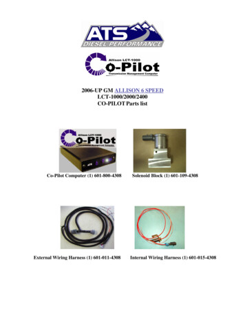
2006-UP GM ALLISON 6 SPEEDLCT-1000/2000/2400CO-PILOT Parts listCo-Pilot Computer (1) 601-800-4308External Wiring Harness (1) 601-011-4308Solenoid Block (1) 601-109-4308Internal Wiring Harness (1) 601-015-4308
Installation ManualCo-PilotTM for 2006-UP GM Allison 6 SpeedLCT-1000/2000/2400Version 1.4This kit makes it possible to transfer increased power levels over stock developed by a modifiedengine to the rear wheels without causing the dreaded transmission slip and “Fail Safe” condition thatplagues the Allison transmission. The Co-Pilot package alone, without any internal transmissionmodifications, allows the transmission to handle approximately 85 more horsepower and 120 footpounds of torque over the power level at which the stock Allison will typically enter into “Fail Safe”mode, roughly 425HP/650Tq. The Co-Pilot kit allows the transmission’s clutch packs to receive fullline pressure (clamping force needed to apply clutches) during high power situations. The stock AllisonLCT-1000/2000 and 2400 transmission’s torque capacity has been reduced by the limited pressure thatis available in the clutch packs. The stock Allison transmission only receives approximately 86-PSI oilpressure to the clutch packs when in 5th gear. After the addition of the Co-Pilot transmission systemthe transmission clutch packs receive approximately 230-PSI, more than 2.5 times the stock pressure.By allowing the available line pressure to the clutch packs, we have designed a system thatincreases the torque capacity of the stock Allison transmission by over 280 foot pounds of torque withthe simple addition of our Co-pilot transmission kit. This increased pressure is only applied duringhigh engine torque output, unlike other mechanical kits that do not use electronic controls. Thisremoves the concern of excessive pressure on vital transmission parts such as delivery rings, drums,shafts, etc. during normal operation. Other valve body kits being sold today perform this hydraulically,only after the trim valve has completed the shift. The problems with these hydraulic kits lie in twoareas. The first is the lack of ability to sense engine torque and to anticipate a shift. This causes theclutches to endure an excessive amount of slip, causing heat during the shift and eventually glazes theshifting clutch packs. The other problem with these mechanical kits is the valves supply full linepressure to the delivery rings in the transmission at all times. This constant high pressure causesexcessive wear in the transmission. We have spent a great amount of time in the engineering anddevelopment of this kit to ensure long transmission life, along with great performance. If the Co-Pilot kit is installed into a transmission that has been pushed into the fail-safe protection mode (neutral) theeffect the Co-Pilot will have on the transmission is not as apparent as when installed on a stocktransmission that has not been previously damaged. After the C-3 (3rd-5th) clutch pack has been glazed afew times the clutch pack looses about 20% of its holding force, in this case the complete ATS HeavyDuty Transmission package may be necessary to repair the previously damaged components inside thetransmission.
Please read all instructions before the installation of the ATS Allison Co-PilotTMThank you for purchasing the ATS Co-Pilot Allison transmission up-grade package. This manual isto assist you with the installation and operation of the unit. If you are installing the unit for a customer,please pass this manual on to your customer for future reference.Features of the ATS Co-PilotTM Allison Package Increases transmission torque capacity over stock Allison LCT-1000/2000/2400Allows full control over transmission shift quality at the touch of a buttonThe only system available that will let the driver select shift firmnessFaceplate on the Co-PilotTM module indicates the enhancement level the transmission receivesAllows shift softness/firmness from mild to wildKeeps the engine off of the rev-limiter at wide open throttle, during high torque demandIncreases transmission life and durability, and reduces transmission fail-safe condition that existsfrom increased power output of engineAutomatic command of the torque converter clutch apply under high power conditionsAllows towing in all gears, including overdrive, with a modified engineWorks with all add on power modules including propane assistWorks in conjunction with the factory computerWill work with all other transmission shift calibration kitsUnderstanding the ATS Allison Co-Pilot Transmission PackageThe ATS Co-PilotTM module controls and increases the load capacity of the Allison LCT-1000automatic transmission based on the amount of increased engine torque. This allows for up to 100% ofthe power developed by the engine to be transferred through the transmission. The ATS Co-PilotTMmodule provides normal factory operation of the transmission when the engine is operated in the lowerpower ranges. As the torque of the engine is operated at increased loads the ATS Co-PilotTM modulewill prevent the transmission from slipping; delivering all of the normally unusable power to the ground.In certain high power situations, the converter clutch is turned on eliminating the slippage through thefluid coupling in the torque converter. This feature is best used with the ATS Five Star torqueconverter. The transmission performance is exceptional and oil temperature will remain low because oflittle to no slippage occurring when the ATS Co-PilotTM module is turned on. When the ATS CoPilotTM module is turned on, you can expect exceptional performance and very responsive shifts.The ATS Co-PilotTM module allows the driver to have control over the engagement of the torqueconverter clutch while eliminating the slip in the transmission clutch packs. The Co-PilotTM module alsoallows the driver to select the shift quality (firmness) desired during heavy acceleration. With thesimple push of a button you can select stock type soft shifts to tire burning performance shifts. Thisfeature is the most popular feature of the ATS Allison Co-PilotTM Pack. Select a soft shift for every daydriving or make a few clicks on the up arrow pad and lay rubber at the racetrack. The glory about thisfeature is its simplicity.Operating InstructionsThe variable control panel on the face of the ATS Co-PilotTM Module allows the driver to select thequality of the transmission shift. The “quality” of the shift is the firmness or softness, this is theduration of time the transmission takes to complete a shift from the time the computer commands a shift
tell the transmission completes a shift. Shift quality is very important, when a shift takes longer thandesired the clutches glaze and eventually burn up causing premature transmission failure. A glazedclutch also has far less holding ability than a good clutch. This is the condition that is caused byinstalling power modules on a vehicle with out taking care of the transmissions first. The control panelface also serves as a boost pressure readout, as engine output torque (boost) rises the lights in the panelwill light starting at the left going to the right. The blue boost indicator lights indicate when thetransmission is being torque enhanced by the ATS Co-PilotTM Module. When the round button on theleft side of the Co-PilotTM face is depressed and the blue light is turned off, the ATS Co-PilotTM Moduleis disabled. This will allow the factory PCM (Power Train Control Module) to operate the vehicle as itis in near stock form. The OFF position is indicated by none of the lights being lit on the face of the boxwhen boost pressure is reached. To activate the unit, depress the round button on the left side of the CoPilotTM face, one of the blue lights on the face will light up, the light also indicates the level the CoPilotTM was set on before it was last shut OFF. This will tell the ATS Co-PilotTM Module to watch forengine load. The torque converter clutch engagement is controlled by two different inputs; vehiclespeed and engine load. This feature is adjustable on the control pad; the ATS Co-PilotTM Modulecontrols lock-up engagement automatically when the Co-PilotTM is adjusted with the Up arrow (BlueL.E.D. lights are to the far right).The up and down arrow keys select the amount of additional load capacity the transmission receivesfrom the Co-PilotTM module based on engine load. This will cause the Co-PilotTM to send a variety ofsignals to the transmission to enhance the torque capacity of the transmission. This option is onlyavailable when the unit is powered on. When the Co-PilotTM is powered off the transmission operates instock form, therefore the transmission will receive no inputs from the Co-PilotTM module. Below is adescription of how to adjust the shift quality.Adjusting Shift FirmnessShift Firmness is adjustable at any time by simply arrowing up or down. The up arrow will firm up theshift quality while the down arrow will soften the shift quality. The Co-Pilot has been designed thisway so you can customize the quality of your shift during your drive. Note: The buttons must be helddown to change the settings. Please see the diagram below.For racing applications hold the UP arrow (increasing shift firmness) for approximately five secondsuntil all of the blue lights simultaneously illuminate. All of the blue lights coming on at once indicatesthe Co-PilotTM computer has been placed into Race Mode. In some cases the Race Mode may cause acheck engine light. This light will not cause any performance problems and will reset itself after a few
ignition cycles. When the Co-PilotTM is placed in the firmest setting (blue L.E.D. all the way to theright) the Co-PilotTM computer will place itself into Race Mode automatically once the transmissionreaches operating temperature. To allow firm shifting without the engagement of the torque converterclutch, place the Co-PilotTM computer one setting below the maximum (the right two blue LEDs will bewill be on and no check engine light will be set at this point).In some cases the transmission computer may inhibit reverse if the check engine light is triggered. Donot be alarmed if this condition exists. After an ignition cycle, reverse will be restored.Installation InstructionsThere are three (3) basic installation steps to this kitA. Valve Body SectionB. Wiring harness installation and the Co-PilotTM boxC. Connect wiring harness to sensorsA) Valve Body Section1) Drain the transmission pan; use a 14 mm socket to remove the drain plug from the bottom of thetransmission pan. You will need a pan with a fluid capacity of approximately 6 quarts of fluid.After draining the transmission pan, place the drain plug back into the pan and torque it to 16foot pounds of torque.2) Next remove the bolts from the outside of the pan that attach it to the transmission case andremove it from the case, use a 13mm socket. Remove the black plastic filter from thetransmission; pull the filter straight down while rotating from side to side to remove it from thecase.3) After the pan and filter has been removed from the transmission allow the valve body to drip fora while to minimize the mess. You are now ready to proceed with the valve body up-grade.4) Un-plug the 20-pin connector from the back of the transmission (Figure 1). The connector canbe difficult to disconnect from the transmission, squeeze the connector and wiggle it from left toright while exerting pressure to the rear of the vehicle. The connector will disconnect from thetransmission with a little effort.Note: The valve body does not need to be removed from the transmission to install the Co-PilotTM.
5) Install the supplied connector from the Co-PilotTM harness in the factory connector’s place. Plugthe factory connector that you removed into the other side of the Co-PilotTM harness.6) Remove the stainless steel tube that is held down by the two bolts shown below in the leftpicture. With a tubing cutter, cut the tube 1-1/4” from the bend shown in the middle picture.Then cut 7/8” off of the section of tubing that does not have the bend you measured from.Bolts for Removal1-1/4” from bend7/8” gap7) Remove any burs from the tubing and make sure to remove all debris. Install the solenoid blockbetween the tubes as shown and put the assembled tube back onto the valve body. NOTE: Becareful when installing the metal tubes into the valve body, gently tap the ends if necessary.Make sure the solenoid’s pin hole is oriented as shown in the picture above.
8) Connect the ATS secondary harness to the external harness. Put the Brown plug into the portnext to the PTO cover as shown below.9) Route the wires as shown in the picture below. Wire tie it where convenient and out of the way.Plug the connector into the solenoid.
10) Take the time to do one last check over the valve body assembly, be sure all of the electricalconnectors are plugged in and all of the bolts are tight then install the internal filter.11) Install the pan and gasket; this is also the time to install an aluminum deep pan if you have one.12) Torque the pan bolts to 18-foot pounds of torque.13) Add 6 quarts of transmission fluid to the transmission after securing the transmission pan to thecase.14) The transmission internal section is done; after the remaining portion of the ATS Co-Pilot kitis completed the transmission fluid needs to be checked immediately after start up. Note: It iscommon to have a check engine light immediately after start up due to low fluid level, after thetransmission is full of fluid and a few ignition cycles the check engine light will reset.15) IMPORTANT! Make sure to recheck the fluid level in the transmission after the vehicle isdriven for a short distance, as it is common for the level to drop.
B) Wiring harness installation and Co-PilotTM Box1) Plug the Co-PilotTM wiring harness into the transmissions round 20-pin connector located on thebackside of the transmission. The supplied connector will plug in between the factory wiringharness and the transmission. Connect the factory 20-pin connector into the other end of the CoPilotTM harness supplied. Be sure the two 20 pin connectors are securely locked into place, thetwo tabs on ether side of the connector make a snapping sound when fully engaged.2) After connecting the male and female ends of the Co-PilotTM wiring harness route the 10-footsection of the harness over the top of the transmission. The white connector will need to berouted to the inside of the cab.3) Route the small white connector side of the wiring harness into the driver’s side compartmentthrough the firewall of the vehicle. There is an access hole in the firewall that can be enlarged toaccommodate the harness.4) Pull the wiring harness through the firewall just enough to connect it to the Co-PilotTM module,ideally to the right side of the driver just below instrument cluster.5) Plug the wiring harness into the Co-PilotTM module; place it in a good location that can be easilyaccessed by the driver. Use brake clean or solvent on the dash where the Velcro will be put toinsure that it sticks properly. Secure the Velcro and Co-PilotTM to the dash.
C) Connecting the wiring harnessWe strongly recommend that you solder all wire connections and protect the soldered connectionswith shrink-wrap.Co-PilotTM WireWire to be tappedCut the wire to be tapped and stripapprox 1/2” of insulation offall three wire ends.Shrink TubingSlide a piece of shrink tubing overone end and twist all three wirestogether one at a time.Thoroughly solder thethree wires togetherSlide the shrink tubing over thesolder connection and gently heattubing with butane torch or lighteruntil a good seal is formed.Making all of your taps this way will give you reliable and long lasting connections.
-Gray Wire with Black Tracer- GND-Exhaust BrakeConnect to the ground-side of the exhaust brake solenoid. Cut the existing solenoid ground and buttconnect to the wire end that goes to the solenoid. The Co-PilotTM will act as the ground to giveoptimal braking performance.-Brown Wire with Green Tracer- MAP SensorThe MAP sensor is located on the front of the passenger side of the engine, between the alternatorand the air intake pipe. The sensor connector has three wires, tap the MAP sensor’s Light Greenwire (middle wire of the connector) with the Co-PilotTM Brown wire with Green tracer.MAPThis connection is critical as it is subjected to harsh conditions. We advise a good solder joint forthis connection and shrink-wrap. Some power modules may also plug into this sensor, if there is anadditional connector plugged into this sensor wire, be sure the Co-PilotTM tap is the closest to thesensor.
-Black Wire- GroundConnect to a bolt or screw under the dash that provides a good ground. For best results, splice thiswire into the black wire with white tracer that comes from ECM pin #1 with solder.-Yellow Wire with Black Tracer- VSS1) Route the Yellow with Black tracer wire from the Co-PilotTM to the Transmission ControlModule (TCM) at driver’s side of the fan shroud.TCM2) Disconnect the plug on the bottom of the TCM by pulling the locking tab towards the fan.
3) Separate the plastic housing by removing the 8 tabs (4 on each side), be careful not to breakthem.4) 2006-2007 LBZ Model Trucks: Locate the yellow wire shown below. Splice the wire about 2inches from the connector. Splice the yellow wire with black tracer from the ATS wiringharness into the yellow wire coming from the connector. Make this splice a couple inches fromthe connector so you have room to work. We recommend solder and shrink wrap for thisconnection over using tapping hardware. 2007.5 LMM Model Trucks: Locate the Purple withWhite tracer wire in PIN#60. Connect the Yellow with Black tracer wire to the Purple withWhite tracer as described above.5) Put the plastic cover back over the wires and reinstall the plug, make sure the locking tab is secure.
Installing the Throttle WireHook up the Brown wire with blue tracer from the Co-PilotTM harness to the throttle positionsensor’s Blue wire by tapping with solder. Be sure to tie the wire up out of the way. On 2007.5LMM model trucks, connect the Brown w/Blue tracer wire of the copilot harness to the Dark-Bluewire in the TPS connector PIN E.
Notes about first startup procedure after installationFor the first 50 miles after installation, set your Co-PilotTM so that the center LED light is on.To avoid a ‘fail safe’ condition and/or check engine light the recommended procedure is to fill thetransmission with a minimum of 6 quarts (with stock pan) of fluid before startup. With the highcapacity pan you will want to add 11 to 12 quarts before startup. Once the engine is started, allow itto run for 4-5 seconds and then shut off the ignition. Allow the vehicle to sit for 5-10 seconds andthen restart the engine. This will purge the air from the system before the OEM computer detects thelow pressure (therefore setting the check engine light and trouble code).Scan ToolsDifferent scan tools can often be misleading. The only scan tools that ATS has found to becompletely effective at clearing trouble codes in the computer is the GM Tech II scanner and theViewtronics hand-held scanner. Many other scan tools on the market display to the user that theyare clearing codes, when in-fact they are not. This condition of not completely clearing the codeshas been exhibited repeatedly with the Snap-On scanners. Disconnecting the battery cables from thebattery terminals WILL NOT clear the codes or the adaptive strategy that governs shift behavior.Feel free to contact our Technical Support Department with questions or for more details.DiagnosticsThe factory 20 pin connector on the back of the transmission can be plugged directly into thetransmission after the Co-PilotTM internals have been installed. This is one method that can be usedto isolate possible electrical issues with the ATS external harness or Co-PilotTM controller.
Bill of Materials1. Co-Pilot controller 601-800-43082. Solenoid block assembly 601-109-43083. External wiring harness 601-011-43084. Internal wiring harness 601-015-43085. Hardware kit (not pictured) 601-001-4248
Understanding the ATS Allison Co-Pilot Transmission Package The ATS Co-PilotTM module controls and increases the load capacity of the Allison LCT-1000 automatic transmission based on the amount of increased engine torque. This allows for up to 100% of the power developed by the engine to be transferred through the transmission. The ATS Co .
