Transcription
11/14/082308-601-900-INSTInstallation Manual v1.5:2006 Dodge CumminsPlease read all instructions before the installation of the ATS Co-PilotThank you for purchasing the ATS Co-Pilot Torque converter/exhaust brake controller. Thismanual is to assist you with your installation and operation of the unit. If you are installing the unitfor a customer, please pass this manual on to your customer for future reference.Understanding the ATS Five Star Co-PilotThe ATS Co-Pilot commands the lock-up clutch of the torque converter along with the exhaustbrake, if equipped, to stay engaged. This allows for up to 100% of the retarding force to betransferred in 3rd and 4th gear and the transmission oil temperature to remain low because of little tono slippage occurring when the converter is in these selected gears. When the ATS Valve Body isinstalled, you can use engine braking in the low-speed position of around 12 mph in 1st or 2nd gear.Currently, exhaust brake usage can cause high temperatures in the automatic transmission due totorque converter slippage. And only a small portion of the retarding force is transferred through thefluid coupling of most torque converters. The ATS Co-Pilot has been developed to provide lock-upcapability in all gears. NOTE: On Dodge transmissions the ATS Valve Body must be installed toutilize 1st and 2nd gear lock-up capability. The factory computer is programmed to disengage lockup under many conditions that inhibit the performance of the transmission. A few of theseconditions are:-Lock-up disengagement at wide open throttleLock-up disengagement at closed throttleDelayed lock-up engagement when accelerating from a stopDelayed lock-up engagement before engine temperatures are reachedLock-up disengagement under high power outputThe factory has programmed the stock computer with these features to minimize the stress on thefactory torque converter. The ATS Co-Pilot allows the driver to have manual control over theengagement and disengagement of the torque converter clutch.The variable control panel on the face of the Co-Pilot allows the driver to select and view the speedat which the torque converter clutch will engage and disengage. When the round button on the leftside of the Co-Pilot face is depressed and the blue light is turned off, the Co-Pilot is disabled. Thiswill allow the factory PCM (Power train Control Module) to operate the vehicle as it is in stockform. The OFF position is indicated by none of the lights being lit on the face of the box. Toactivate the unit, depress the round button (ATS Button) on the left side of the face, one of the bluelights on the face will light up, the light also indicates the level the Co-Pilot was set on before it was1
11/14/082308-601-900-INSTlast shut OFF. This will tell the Co-Pilot to watch for vehicle speed. The minimum speed the CoPilot will engage is around 12 mph. The minimum speed of around 12 mph is selected bydepressing the down arrow button on the display. This will cause the Co-Pilot to send a signal tothe transmission (and exhaust brake if equipped) to lock-up the torque converter at its minimumallowable speed. When the up arrow key is depressed the lock-up speed will increase by about 5mph. When the down arrow key is depressed the lock-up speed will decrease by about 5 mph. Oneof the blue lights on the right side of the display will indicate the set speed selected by the driver.When the blue light is at full right the lock-up speed is indicating a maximum set speed around 55mph. Note: the factory TCC apply signal from the factory PCM will pass through the Co-Pilot ifthe factory PCM signal is commanded (turned ON) before the Co-Pilot sends the lock-up signal.When the ATS Co-Pilot is turned ON the torque converter will not disengage until the minimum setspeed is reached. The Co-Pilot is easy to operate. Unlike other torque converter controllers, itoffers variable lock-up speed control. The adjustable control panel allows the driver to select thevehicle speed at which the torque converter locks up. To better understand how the Co-Pilot isoperated, we recommend you look at the illustration provided.There is an OFF position and an ON position. The OFF position disables the Co-Pilot and allowsthe factory computer to operate the torque converter lock-up command as if the Co-Pilot was notinstalled. The OFF position also serves another function when used with an exhaust brake, the CoPilot has been designed to operate the torque converter clutch along with operating most exhaustbrakes. When the Co-Pilot is in the OFF position, it energizes the exhaust brake (if the exhaustbrake is turned ON). Many people prefer to use the exhaust brake as an engine warmer in coldconditions. In order to use the exhaust brake as an engine warmer all that is necessary is to turnOFF the Co-Pilot and turn ON the power to the exhaust brake. When the Co-Pilot is powered ON,the exhaust brake will only engage when the torque converter clutch is engaged. When the Co-Pilotis sending the apply signal to the converter clutch and exhaust brake the green light in the controlpanel will illuminate. When the Co-Pilot disengages the torque converter clutch, the exhaust brakealso turns OFF at the speed previously selected by the driver. We have designed this feature intothe Co-Pilot to automate the torque converter clutch and exhaust brake actuation. This eliminatesthe need to turn OFF the exhaust brake when coming to a stop. This feature has been designed forheavy pullers that require engine braking at low speeds. The ATS Five Star Converter and ATSValve Body have been designed to maximize this feature. The minimum set speed position of theATS Co-Pilot will only be effective when installed with the ATS Valve Body. You can use thisfunction on a stock valve body, however you will not notice a difference in performance at lowspeeds due to the design of the factory valve body. When used with the ATS Valve Body and ATSFive Star Converter, you will find you can have 100% engine retard down to around 12 mph.2
11/14/082308-601-900-INSTBelow this speed, the torque converter clutch and exhaust brake, if equipped, will automaticallydisengage. When used with the factory (stock) valve body you will not be able to utilize the 1st or2nd gear lock-up feature, lock-up will only occur in 3rd and 4th gear. The ATS Co-Pilot works off ofan interface that will only take effect when the vehicle is above the speed selected by the driver.The best way to familiarize yourself with the operation of the ATS Co-Pilot is to set the ATS CoPilot to the maximum (highest) set speed (up arrow) available. Hold a steady speed ofapproximately 35 mph. While cruising at a speed of 35 mph, depress the down arrow on thecontroller panel, watching for the green light on the ATS Co-Pilot to illuminate; about 3 secondsafter the light illuminates, the torque converter clutch should engage. You can familiarize yourselfwith the adjustment of the control panel by repeating this step at different speeds below the postedspeed limit.Operating Instructions when used with the ATS Valve Body and Five Star ConverterWhen the ATS Co-Pilot is used in conjunction with the ATS Valve Body and Five Star Converter, you can also use the lock-up feature in manual 2nd and manual 1st gear. When the ATSCo-Pilot is used in conjunction with the ATS Valve Body, you can shift from 4th to 3rd withoutdisengaging the torque converter clutch. This feature is designed with safety in mind; the vehicle iseasier to control when down shifting from 4th to 3rd gear when it is heavily loaded. The lack of theTCC disengaging then having to re-engage is a positive feel of the transmission and convertershifting. When the ATS Co-Pilot is used in conjunction with the ATS Five Star Converter thereis no need to feather the throttle pedal when attempting to apply (stop) the converter clutch, just turnit on and off at will. Set #1 dipswitch to OFF to take advantage of the ATS Valve Body.Operating Instructions when used with a factory or stock valve bodyDuring deceleration on vehicles with a stock type converter, the lock-up clutch can be manuallyengaged by applying pressure to the accelerator pedal until lock-up engages, after the converterclutch has been seated, lift your foot off of the accelerator. Accelerator pedal pressure is alsorequired after shifting out of or into overdrive to reengage the lock-up clutch. The ATS Co-Pilot isprogrammed to disengaged the lock-up clutch and exhaust brake if equipped once the vehicle’sspeed drops below the pre-selected set speed selected by the driver when in the ON position. Forproper operation of the Dodge transmission with a stock valve body, the lock-up clutch must bedisengaged before the transmission will shift out of overdrive 4th and into 3rd gear. The ATS CoPilot compensates for this by disengaging the lock-up clutch for 2.5 seconds when the (O/D) buttonis activated. To reactivate the lock-up, apply pressure to the accelerator pedal until lock-upengages, then lift your foot off of the accelerator pedal. The factory valve body and most aftermarket valve bodies will not make a shift from 4th gear to 3rd gear with out releasing the torqueconverter clutch momentary, this causes additional stress on the torque converter clutch when theconverter clutch is re-engaged after the 4-3 shift takes place. This is the reason it is important toapply throttle pressure during the 4-3 down shift to synchronize the converter clutch to the engine.Set #1 dipswitch to ON for use with stock valve body.Setting up the ATS Co-Pilot for installation3
11/14/082308-601-900-INSTThe ATS Co-Pilot will need to be set up for your vehicle and application. The Co-Pilot will need tobe disassembled to access the dipswitches on the electronic board. You will need a 1/16th - inch hex(Allen wrench) to remove the face from the Co-Pilot. After the face has been removed theelectronic board can be slid out of the casing from the front. The digital face is attached to thecircuit board with a ribbon cable; do not force the board from the case. There are four (4) switcheson the circuit board; the switches allow the user to select the features desired. The settings are listedbelow. When reinstalling the face on the Co-Pilot do not over tighten the 2 small screws on theface.Dipswitch h #1If your Dodge’s transmission has a stock valve body flip #1 switch to ON positionIf your Dodge’s transmission has an ATS valve body flip #1 switch to OFF -------------------------------------------Switch #2Automatically cancels OD from a stop, only cancels after ignition has cycled, cancels at speedabove 3mph.IMPORTANT: If the white wire of the Copilot harness is not connected, then switch #2 mustbe set to the “ON” position. With the wire connected the options below are available.If you want automatic OD cancel from a stop flip #2 switch ONIf you do not want automatic OD cancel from a stop flip #2 switch ---------------------------------------Switch #3Speed settingOn low speed cut out is 8mphOff low speed cut out is around 18mph, recommended -------------------------------------------Switch #4Set this switch to the ON -------------------------------------------We have preset the Co-Pilot module #1-ON, #2-ON, #3-OFF, #4-ON (Stock valve body, automaticoverdrive cancel turned off, 18 mph cut-out).WiringDisconnect Ground (Negative) terminals on all vehicle batteries before starting installation. Thefollowing instructions will be divided up for wiring up each individual wire color labeled on theATS Co-Pilot. Follow along with the diagrams after the written instructions for ease of installation.Solder all connections for reliable results. These wire connections must be shielded from theelements (we recommend heat shrink tubing).4
11/14/082308-601-900-INSTNOTE: When wiring the Co-Pilot, consider leaving enough slack on the wires so that it can berelocated later, if needed. Reconnect all ground terminals on batteries after installation.Co-Pilot Mounting LocationFind a convenient location to mount the Co-Pilot within reach and view of the driver. Werecommend locating the unit just to the right of the driver on the lower dash panel (above thedriver’s right knee). Use the supplied Velcro to secure it to the dash. Before sticking the Velcro tothe dash thoroughly clean the area with a cleaner such as acetone or brake clean. Run the Co-Pilotwires to be wired up to the PCM, MAP sensor, and the transmission through the firewall.-Pink Wire- Throttle Position Sensor (TPS) – PIN #12Connect at the TPS connector located at the top of the accelerator pedal arm under the dash. It iseasiest if you unplug the connector to access the wire. This is a six-wire connector. In the fifthterminal there is a brown with white tracer wire, tap this wire with the Co-Pilot’s Pink wire usingthe technique shown in the second to last page in this manual.The remaining wires must be ran through the firewall to the engine compartment.-Tan Wire- PRNDL– PIN #8Connect at the 6-pin transmission range sensor located on the driver’s side of the transmission nearthe pan rail. Tap into the dark green with yellow tracer wire with the Co-Pilot’s Tan wire. Usethe technique shown in the second from last page of this manual.-Orange Wire- Manifold Absolute Pressure (MAP) Sensor - PIN #4Connect at the MAP sensor connector located on the driver’s side of the engine, next to the valvecover, and just over halfway back on the engine. The connector has four wires; tap into the lightblue wire, which is in the fourth (“D”) terminal. Use the technique shown in the second from lastpage of this manual.Important: If the vehicle has had any aftermarket power modules installed, be sure to tap the MAPsensor wire before any taps from these power modules, i.e. place the Co-Pilot’s tap closest to thesensor. The Co-Pilot may not work properly if it receives signals that have been modified by otheraftermarket devices. The Co-Pilot does not modify the signal and will not interfere with any otherdevices that are connected “down stream”.The following wires need to be attached at the vehicle’s PCM, which is located on the driver’sside of the engine block. There are two connectors here; the Co-Pilot wires go to the “B”connector, which is the rear, 50-pin connector (the one closer to the firewall). It is easier toaccess the wires in this connector by unplugging it. To unplug it, loosen the Allen screw thatis located in the middle of the connector’s wires using a size 4 metric Allen (5/32 standard canalso be used, but be careful not to strip the head). Next, remove the bolt that holds a wireloom clamp above the connector. When finished, reattach the connector.5
11/14/082308-601-900-INST-Red Wire- 12V Power - Co-Pilot Harness PIN #1Connect at the “B” connector of the PCM into the Pink w/ gray wire in pin 32. Use the techniqueshown in the second from last page of this manual.-Black Wire- GND Ground - PIN #9Connect at the negative (-) terminal of the battery. Connecting to PCM pin #50 caninterfere/malfunction when used with some aftermarket modules.-White Wire- Overdrive - PIN #5Connect at the “B” connector of the PCM into the Dark Green wire in pin 13. Use the techniqueshown in the second from last page of this manual.-Green Wire- VSS - PIN #17This wire leads to the transformer that is incorporated into the harness. Three wires lead out of thetransformer: black, brown, and purple. The black wire is already connected to GND Pin #9.-Brown Wire- From TransformerConnect at the “B” connector of the PCM into the Dark Green wire with Brown tracer in pin 44.Use the technique shown in the second from last page of this manual.-Purple Wire- From TransformerConnect at the “B” connector of the PCM, into the Dark Green wire with Purple tracer in pin 45.Use the technique shown in the second from last page of this manual.-Yellow Wire- PCM – PIN #10 and -Blue Wire- TCC – PIN #11Connect at the “B” connector of the PCM, into the yellow with light blue tracer wire in pin 25.Cut the yellow with light blue tracer solder and shrink-wrap the end that leads into the harnesstowards the transmission to the Co-Pilot’s Blue wire. Solder and shrink-wrap the end that leads tothe PCM plug to the Co-Pilot’s Yellow wire. Reference the attached wiring diagram.-Gray Wire- Exhaust Brake (Vehicles with exhaust brake only) – PIN #13If you do not have an exhaust brake, skip this section.Cut the Exhaust brake solenoid’s ground wire and attach it to the Co-Pilot’s Gray wire with shrinkwrap and solder.6
11/14/082308-601-900-INSTYou can use the warm-up feature of your exhaust brake by simply turning off the Co-PilotBox and turning on the exhaust brake’s toggle switch.-Diode- All models with Exhaust BrakeThere is a stripe on the diode that indicates the positive side. Attach the positive side of the diode topin 85 of the Pacbrake relay. Attach the negative side of the diode to the gray Co-Pilot wire. Seethe provided wiring diagram for clarification.Testing w/ Exhaust BrakeTurn the ATS Co-Pilot OFF (Button on left of display panel-no lights on). Turn the exhaust brakeON. The exhaust brake should sound. Turn the Co-Pilot ON, the blue light on the display shouldilluminate and the exhaust brake should turn OFF. Take the vehicle for a drive. Set the lock-upspeed to the minimum speed (18 mph mark) and first check that the green LED light comes on oncethe vehicle has surpassed the set speed of around 18 to 20 mph. If the LED fails to illuminate afterthe set speed, check the VSS wire color and the connection to that wire. With no traffic around,turn ON the exhaust brake and set the Co-Pilot to engage at a speed of around 35mph, then cruise ata constant speed above the set speed on the Co-Pilot then let off the throttle. The brake should haveactivated and you should feel the deceleration. Turn the brake OFF to make sure the brake andlock-up clutch disengages. Turn the brake ON and cruise again at a constant speed, then let off thethrottle and let the vehicle slow down below the set speed, making sure the lock-up releases belowthe set speed. If these situations fail to occur, then check the wiring to the brake and Co-Pilot.With the exhaust brake ON, turn the Co-Pilot OFF. The exhaust brake should activate.If any of the functions still fail to occur go through all of your connections thoroughly and verifyyou have good power and grounds along with a good vehicle speed connection. The VSSconnection is the most common cause of a malfunctioning Co-Pilot. If you cannot determine thecause of failure, call our Tech Department for assistance. If required to bypass the effects of theCo-Pilot unplug the main connector on the back of the unit and connect the Blue and Yellow wirestogether. Secure any loose wires after final wiring and testing has been done.Understanding the operation of the ATS Co-PilotWith the ATS Co-Pilot turned ON while driving and the exhaust brake turned ON, the transmissionshifts from first to second to third and then locks up. Anytime after the lock-up has occurred andyou take your foot off the accelerator, the ATS Five Star Co-Pilot will hold the torque converterclutch locked until the minimum set speed the adjustment has been set to and then it will turn off thetorque converter clutch and the exhaust brake. When driving on the freeway in overdrive, with thetorque converter clutch locked up and the exhaust brake turned ON, releasing the throttle will makethe ATS Five Star Co-Pilot hold the torque converter clutch locked up, along with the exhaust brakeengaged.On the Dodge with a stock torque converter, when downshifting you have to apply throttle pressureuntil the factory computer says everything is okay and locks up the torque converter clutch. Assoon as that happens, you should remove throttle pressure and the Co-Pilot will keep the torqueconverter clutch applied until you get down to the set minimum speed mark. When the Co-Pilot is7
11/14/082308-601-900-INSTused with the Converter and ATS Valve Body the converter can be locked and unlocked at will,feathering the throttle will not be necessary to aid in converter clutch apply.There may be times when you need to make a quick stop or slow down, where canceling the ATSCo-Pilot functions may be needed. Such conditions may be:-You do not require the extra retarding horsepower of third gearYou do not want the shuddering that occurs when you have a locked up torqueconverter clutch and you are going to be doing less than 32 mph in overdriveYou can do any of the following four actions to cancel out the system1. Turn OFF the Five Star Co-Pilot2. Lightly step on the throttle pedal3. Pull the gearshift lever down into second gearThe ATS Co-Pilot function should only be used under moderate throttle applications when usedwith a stock valve body. Unless you have installed the ATS Five Star Converter, the stockconverter clutch has only so much holding power and exceeding this will start to slip the clutch,thereby starting the demise of your converter clutch. An example of when to use the ATS Co-PilotsON position would be when you are on a winding road where you are on and off the throttle afrequently and you do not want the ECM locking and unlocking the converter clutch. The ATS CoPilot will hold the converter clutch locked up, preventing that from happening. You must keep inmind while doing this that if you apply too much throttle pressure, especially at the lower rpm band,you may start to slip the stock converter clutch. On the 48-RE (2003-up) transmission this is not aproblem unless there have been engine performance modifications. When using this with the ATSFive Star Converter and ATS Valve Body, you can lock the converter at your discretion at anypower level.Information when installing the Co-Pilot with a stock valve body & ConverterThe ATS Co-Pilot has been designed to operate an exhaust brake and engage the torque converterclutch enabling superb engine braking with your automatic transmission. The Co-Pilot must beused only under certain operating conditions to ensure long life of your stock automatictransmission. Using the Co-Pilot on a weak transmission or torque converter can cause prematuretransmission and torque converter failure. There are a few precautions that can be preformed afterthe installation of your new exhaust brake and Co-Pilot. In order to ensure the health of your stocktransmission and torque converter you must perform a few simple tests to your transmission using abasic 0 to 250 PSI pressure gauge. The majority of transmission and torque converter failurescaused by exhaust brakes are a result of improper set up and installation of exhaust brakes ontransmissions that have had prior problems. A list of common problems found ontransmission/converters is listed below. If your stock transmission/converter has ever shown any ofthe signs it is highly advisable to follow the recommended recommendations to correct it beforeusing your newly installed exhaust brake and Co-Pilot.1) Excessive transmission heat, heat that has been developed from slipping clutches.Primarily that of the torque converter clutch. Heat that is developed from the fluidcoupling portion of the torque converter is not a problem such as backing up a heavytrailer into a driveway. Heat that has been generated during a hard pull during lock-up isa direct tell-tell sign of potential prior problems.8
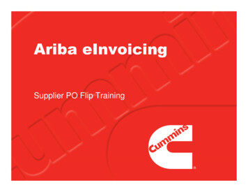
11/14/082308-601-900-INST2) Torque converter clutch chatter is usually the most common sign of converter failure. Achatter or vibration condition that appears around the speed of 42 to 55 MPH is a suresign of a glazed converter clutch. A glazed converter clutch will only have about 2/3rdsof its torque capacity. If you have ever experienced this condition do not use yourexhaust brake or the Co-Pilot until the condition is repaired.3) A transmission that neutrals unexpectedly is also a sign of a misadjusted throttle cable, ifa transmission is driven around with a misadjusted, disconnected or broken throttle cablethe transmission and converter will quickly be damaged.4) Burnt or contaminated transmission fluid. Transmission fluid is normally red, if yourtransmission fluid is brown or black have the transmission pan removed and inspectedfor damage. Brown or black fluid is caused from excessive slipping or clutch materialmixing with the transmission fluid.Providing none of the four items listed above have previously happened to your transmission youare ready to perform the test to ensure your transmission/converter will serve you reliably. Use a 0to 250 PSI pressure gauge to check your transmissions line pressure. Install the line pressure gaugeinto the main line pressure tap located in the passenger side center of the transmission.Figure 1 - Line Pressure TestTape the gauge to the outside of the windshield; this is a precautionary measure to ensure you donot have an accident in the event there is a hydraulic leak. First bring the transmission and engineto full operating temperature, then note the line pressure at idle in neutral. Be sure the engine has anidle speed of at least 750 RPM. If the engine idle is below 750 RPM the line pressure test will showlow. The idle line pressure test should be a minimum of 58 PSI. If the pressure recorded here isbelow 58 PSI then the low-pressure problem must be resolved before proceeding. The mostcommon condition for low base line pressure is low engine RPM. If the engine is at 750 RPM orabove the transmission pressure regulator will need to be adjusted to maintain the minimaloperating line pressure.9
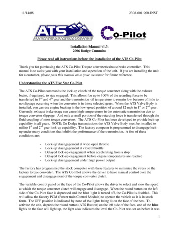
11/14/082308-601-900-INSTFigure 2 - Pressure Regulator Valve AdjustmentThe transmission pan will need to be removed to perform this task. The pressure regulatoradjustment is on the driver’s side of the transmission on the front of the valve body. Use a 5mmhex wrench to increase the spring pressure on the main pressure regulator spring. Rotate the hexbolt counter clock wise to increase the spring pressure. Use the illustration provided to set to theproper spring load. After adjusting the spring to the proper load retest the base pressure. If the basepressure is not adequate after adjusting the pressure regulator this typically indicates a wornhydraulic transmission pump or worn transmission valve body. In this event the transmission willneed internal repairs or the valve body may need to be up-graded. In most cases the valve body canbe up-graded to achieve the desired results.The second test that needs to be performed requires driving the vehicle under a braking conditionwith the ATS Co-Pilot on. The exhaust brake does not need to be on at this point, only the Co-Pilot.While decelerating, watch the pressure gauge. The pressure gauge should indicate at a minimumpressure of 58 PSI during a deceleration condition with the converter clutch disengaged. When thegreen light is illuminated on the Co-Pilot and the converter clutch is engaged you will see about a12-15 PSI rise in line pressure to a maximum pressure of 69 to 71 PSI. This increased line pressureis important for the survival of a stock torque converter clutch. Once you have ensured thetransmission line pressure is properly adjusted you can go forward with the final portion of this test.With the transmission pressure set to the desired level accelerate the vehicle to a safe highwayspeed of around 50 MPH. Turn on the exhaust brake and ATS Co-Pilot. Remove your foot fromthe throttle. The green light should illuminate on the Co-Pilot. If the green light does not illuminateon the Co-Pilot, push the down arrow button to lower the commanded set speed. Listen for theexhaust brake to sound. The green light and the exhaust brake will function together. After youhave ensured the exhaust brake commands properly it is time to check for any harmful slippage thatcould cause torque converter and/or transmission damage. With the torque converter clutch andexhaust break engaged watch the tachometer very closely. While deceleration on a steep grade withboth the converter clutch and the exhaust brake engaged slightly apply pressure on the throttle pedalto disengage the exhaust brake and assist the engine with acceleration. The tachometer should notvary more than 150-RPM during this test. This is a very effective way to check for harmfulconverter clutch slippage. If the tachometer shows more than 150-RPM difference during this testthis indicates your torque converter clutch or hydraulic system is weak, if operated with this10
11/14/082308-601-900-INSTcondition present you will most likely damage your transmission. During a decelerating conditionwhen engaging the exhaust brake it is some times helpful to apply a little pressure to the acceleratorpedal to synchronize the engine speed to the transmission speed. After the engine has synchronizedto the transmission remove all pressure from the accelerator pedal and continue braking. If all ofthe above tests have passed you should not see any problems with the reliability of yourtransmission or torque converter. Things do change over time and as equipment wears the integrityalso diminishes, always give special attention to the operation condition of your transmission andtorque converter when using your exhaust brake. It is also advisable to install a transmissiontemperature gauge to warn of any potential slippage that may occur. These products and manyothers can be obtained from ATS Diesel Performance or directly from the web s
The best way to familiarize yourself with the operation of the ATS Co-Pilot is to set the ATS Co-Pilot to the maximum (highest) set speed (up arrow) available. Hold a steady speed of approximately 35 mph. While cruising at a speed of 35 mph, depress the down arrow on the controller panel, watching for the green light on the ATS Co-Pilot to .