Transcription
T I M B E RR O O FT R U S S E SFIXING & BRACINGGuidelines forTIMBER ROOF TRUSSESThe Timber Roof Trusses you are about to install have beenmanufactured to engineering standards. To ensure that the trusses perform,it is essential that they be handled, erected and braced correctly.2014 - ISSUE 1VIC (03) 8795 8888 NSW (02) 8525 8000 QLD (07) 3861 2100 SA (08) 8234 1326 WA (08) 9412 3534 New Zealand (09) 274 7109
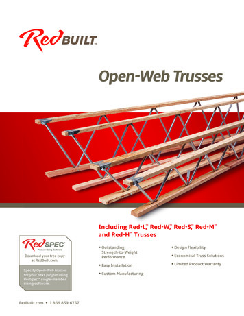
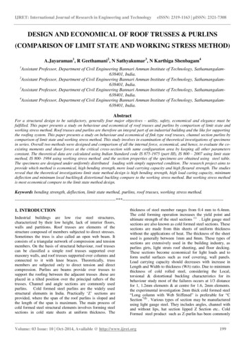
GeneralJob Storage and LiftingThe roof trusses you are about to install have been manufactured toengineering standards. To ensure that the trusses perform as designed it isessential that they be handled, erected and braced correctly. The installationof prefabricated timber trusses is covered by the Australian Standard AS4440“Installation of nailplated timber trusses”. The following information is anabbreviated set of instructions designed to assist with on site work and isnot intended to replace the need to reference AS4440. The followingrecommendations apply to roof trusses on standard domestic buildings wheretruss design details are obtained from MiTek engineering programs. Detailsfor commercial, industrial and non standard domestic buildings, are to beprovided by an Engineer responsible for the overall building design.Trusses should be inspected on arrival at site. Any damaged trusses shouldbe reported immediately and not site repaired without approval of the trussfabricator.Where it is anticipated that trusses will be stored on site for an extendedperiod of time before use, adequate provision should be made to protecttrusses against the effects of weather.Once trusses are installed they should not be left exposed to weather for longperiods. Repeated wetting and drying has a detrimental effect on the strengthof both timber and connection.Protective covering, where used, should allow free air circulation aroundtrusses.Trusses when stored on the job site should be on timber fillets clear off theground and in a flat position to avoid distortion.When lifting, care must be taken to avoid damaging of joints and timber.Spreader bars with attachment to the panel points should be used where spanexceeds 9000 mm. Never lift by the apex joint only.The trusses may also be placed on the top plates by pulling them up on skids,spread at 3000 mm, taking the same precaution as described above.Ensure that the trusses are not distorted or allowed to sag between supports.The recommended method of lifting trusses will depend on a number offactors, including truss length and shape.In general, sling truss from top chord panel points as shown below. Slingsshould be located at equal distance from truss centreline and beapproximately 1/3 to 1/2 truss length apart.The angle between sling legs should be 60 or less and where truss spans aregreater than 9000 mm a spreader bar or strongback should be used. Sometypical examples are shown below.Design1.2.3.4.5.6.Trusses are designed for normal roof, ceiling and wind loads to suitspecific jobs and conditions. Additional loading such as Solar Units, HotWater Tanks, Air Conditioning, etc. require special consideration. Adviceshould be sought from the truss fabricator prior to commencingconstruction.Wall frames and beams supporting trusses must be designed for thecorrect roof loads. Refer AS1684 “Residential Timber-FramedConctruction” for details.Wind load is an important factor in the design and performance of rooftrusses. Ensure that you have correctly advised the truss fabricator withregard to wind load requirements and that adequate provision has beenmade to fix trusses to the support structure to withstand wind uplift forces.Trusses are generally designed to be supported on the outer wall withinner walls being non load bearing. Where it is necessary to use internalwalls for load bearing, these will be clearly shown on layouts. Note thatthe supporting structure is stable in its own right.Before ordering trusses, ensure that your particular requirements havebeen provided for and that all relevant information has been supplied tothe truss manufacturer. If non standard trusses are being used, ensurethat erection and bracing details are known before erection commences.For environments where the atmosphere may be conducive to corrosion,such as some types of industrial and agricultural buildings, or buildingsnear the ocean and subject to salt spray, consideration should be givento the use of G8S stainless steel connector plates.60 or lessImportant Note1.2.3.4.5.6.7.It is the Builder’s responsibility to ensure that all relevant informationrequired for design is provided to the fabricator at time of orderingtrusses, including spans, pitches, profiles, quantities and loadings. Finalconfirmation of details by the fabricator with the builder is recommendedprior to manufacture.Trusses are designed to be part of a structural system, which includesbattens/purlins, bracing, binders, fascias and the connection of thesecomponents. The full strength of trusses is not achieved until allcomponents are installed correctly. All trusses must braced (temporaryand permanently) and stabilised throughout installation of the roof trusssystem. No truss should be loaded until all permanent bracing is fixedand battens/purlins are installed. Installers should not stand on any trussuntil all temporary bracing is fixed in place and the truss is stabilised inaccordance with the following instructions.As truss installation invariably involves working at heights, a riskassessment should be undertaken for each site and all relevantworkplace safety practices followed. With every roof structure and jobsite, conditions are different. It is the builder’s responsibility to considerthese conditions when determining the procedures to be adopted in liftingand fixing roof components. The procedures should be discussed with allsub-contractors and employees on site and the agreed methodsdocumented. The Housing Industry Association (HIA) has published adocument called ‘Safe Working Method Statement No.10’ which hasbeen found satisfactory for this purpose and suitable for many job sites.This document may be obtained from the HIA or your truss supplier. SafeWork Australia has also published “The National Code of Practice for thePrevention of Falls in Housing Construction”. This code contains specificguidance for all those who work in the residential construction sector,including information for adopting a risk management approach for allwork at height in housing, as well as detailed guidance when working at2 metres and above.Ensure all bracing is permanently fixed and all brackets are fully installedprior to working on or loading the roof.Trusses are designed for specific loading, geometry and supportconditions. Under no circumstances should truss timber be cut, removedor trusses be modified in any way without prior approval from the trussfabricator.Trusses should not be used or stored where they are subjected torepeated wetting and drying as this has a detrimental effect on thestrength of both timber and connections.If trusses have been designed for timber fascias, do not replace with steelfascia without asking your truss supplier to check the overhang design.Approx 1/2 to 1/3of truss lengthSpreader barApprox 1/2 to 1/3of truss lengthSpreader barStrongback tied to eachintersecting webof chordApprox 1/2 to 1/3of truss lengthStrongback tied totop chord at aaprox.300mm intervalsTransportTrusses must be fully supported when being transported in either a horizontalor vertical plane. Care must be taken when tying down, not to put strain onchords or webs.Timber or metal right angle protectors are a satisfactory method of avoidingdamage. Unloading and handling is described opposite.Approx 1/2 to 1/3of truss length2
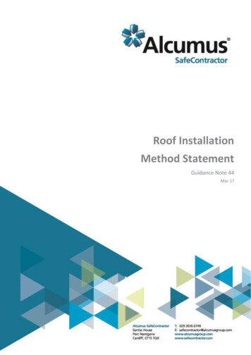
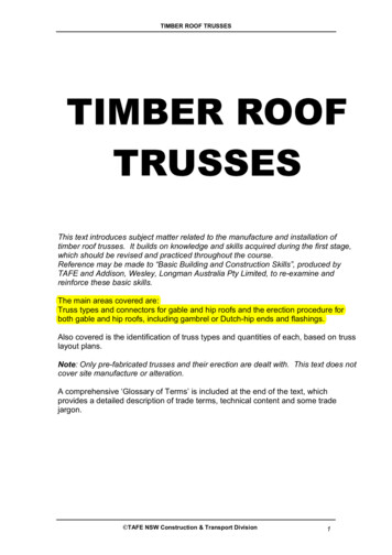
Roof LayoutNote: For 900mm spaced trusses, plasterers prefer to use 50mm battens.A layout for trusses must be determined before erection. If in doubt consultyour truss fabricator.Points circled on these layouts may be critical. Refer to the Wall FrameConstruction Notes.Hip truss/rafterTruncated girderHip EndWall Frame ConstructionRidgeThe load bearing frames should be checked for:1.Standard trussFix at crossing with minimumof 1 TRIP-L-GRIP (typical)Dutch Hip2.Jack truss/rafter3.Hip truss/rafterDutch hip girderLintel sizes suitable for truss loading. Consult AS1684 or your trussfabricator.If trusses are not located directly over studs the top plate size must bein accordance with AS1684.Girder trusses may require the strengthening of studs at the points ofsupport. Check the loading with your truss fabricator and refer toAS1684. Points circled on the layout notes are critical.The supporting structure construction must be adequate to resist windup-lift forces.RidgeTrussesTop plateStandard trussGableJack truss/rafterRaking trussStudsTrussesRidgeTop plateLintel at openingStandard trussVerge trimmingTop plate strengthening may be required where trusses do notcoincide with studs.NOTE: End gable truss to be located over end wall unless otherwiseadvised by supplier.T ShapedRaking trussPlace 75 x 25mm intermediate ties on topchord between saddle trusses where spacingexceeds top chord design restraint centres.StandardtrussTrussesTop plateStudsRidgeFrame BracingRidgeVerge trimmingGirder trussThe frame must be fully braced, plumb, and nailed home before the erectionof trusses is commenced.Raking trussErection and FixingSaddle trussIt is convenient to mark the truss position on the wall plates before liftingtrusses. Use the layout drawing as your guide and note that the truss designspacing must not be exceeded.Verge trimmingL ShapedTruncated girderHip truss/rafterStandard trussEnsure first truss is installed carefully and within erection tolerances.WARNING – Do not use web as ladder to climb up or down the roof duringinstallation. This can cause damage to the web and lead to serious injury.Jacktruss/rafterRidgeGable Roofs – start with a gable truss at each end, fixing it to the top plateat the position marked. These trusses must be temporarily braced back tothe ground or frame at the panel points.Saddle trussGirder trussRidgeHip or Dutch Gable – start with the Dutch girder truss or the truncatedgirder, placing it on the top plate at the position marked and temporarilybracing it back to the frame. Locate hip and jack trusses and adjust girdertruss position before fixing.Intermediate tiesas aboveGable EndsRaking trussLine – Using a stringline along the Apex, place each intermediate trussand fix it to the top plate at the position marked,spacing it with gauging rods and ties.Verge trimmingWhere a gable end is required, consult your truss fabricator for details ofconstruction and erection.Supporting Structure (Frame or Brick)String lineA structure that is not level and is out of square will result in an ugly andunsatisfactory roof line.Time is well spent in ensuring:1. The load bearing top plates are level.2. The structure is of the correct dimension.3. The top plates as well as being level, are straight in their length .4. The internal walls are set below the outer wall level by:Unbattened ceiling – 10mm.Battened ceiling – 10mm plus batten thickness.Spacing Trusses3
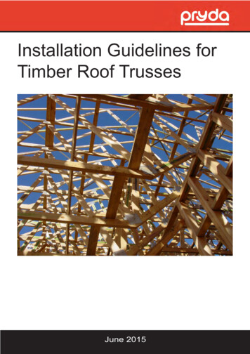
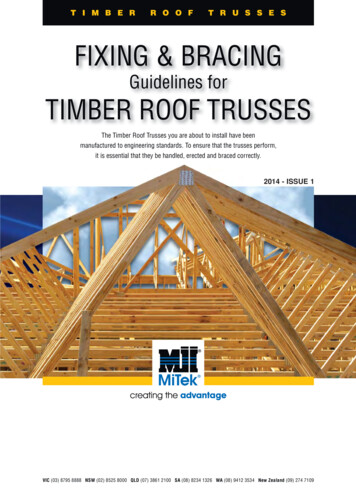
CamberDo not stand on a truss that does not have all its TrussSpacers ortemporary ties fixed.Trusses are built with a camber in the bottom chord. The camber isdesigned to suit the span and load. A girder truss will have more camberthan other trusses. The camber is progressively taken up as the load fromthe roof covering and ceiling is applied. Under no circumstances shouldtrusses be supported along the span (unless designed for) by blocking orpropping.The purpose of temporary bracing is to hold trusses straight and plumb priorto fixing permanent bracing. All permanent bracing, ties, hold down, etc.must be fixed prior to loading roof.Code requirements - Australian Standard for the installation of nailplatedtrusses AS4440 requires that temporary ties are to be used on top chordsat spacings no greater than 3000mm and on bottom chords at spacings nogreater then 4000mm. However, it is good practice to place top chord ties ateach top chord panel point.If a truss has been designed to be supported internally a “SUPPORT HERE”label is affixed to the appropriate point.The TrussSpacer is designed to replace the temporary chord ties asrequired by AS4440. To conform with AS4440 requirements useTrussSpacers as below.3000mm(max)Standard layoutCamber3000mm(max)3000mm(max)Erection Bracing3000mm(max)The trusses must be braced during erection. Ifthis is not done, then two problems can occur.4000mm(max)4000mm(max)1.Collapse during erection2.Erection tolerance will be exceeded, causing overloading, buckling andpossible permanent damage.Alternative layoutThe exact details of erection bracing will, for practical purposes, differ fromjob to job. The following recommendations are for guidance only as thedetails employed are the erectors e first truss should be erected straight and plumb to erection tolerancesgiven previously and temporarily braced to a rigid element, e.g. wall orground as shown on diagram following.4000mm(max)TrussSpacers.Temporary post fixed to wall frame.One per top chord panel point.4000mm(max)See TrussSpacer Installation Instructions for further information.TrussesGableTrussSpacers to thetop of truss top chordsat panel points.Truss beinginstalledPreviously braced trussWallTrussesTrussSpacers to theBottom Chord.Solid props fixed to groundat panel points.WallTrussSpacer: GTS600 for 600mm centres, GTS900 for 900mm centres.Important NoteThese recommendations are a guide only for the erection of standard gabletrusses up to 13000mm span, and spaced at centres not exceeding1200mm. For trusses beyond these conditions, consult your truss fabricator.TrussSpacerTrussSpacersErection TolerancesTolerance is critical for both a good roof line and effective bracing.A stringline, a plumb line or level should be used.TrussSpacerBraceTrusses to be erected with minimal bow, in the truss and in any chord,with a tolerance not exceeding the lesser of L/200 and 50mm, where Lis as defined as shown in diagrams.2.Trusses to be erected so that no part of the truss is out of plumb with atolerance exceeding the lesser of height/50 and 50 mm.Generally if a bow or tilt is evident to the eye, the truss has beenerected outside the tolerances.TieBraceBowTieTop Plate1.BracePlumbTrussEach successive truss should be spaced using TrussSpacers.TrussSpacers are recommended in lieu of gauging rod or timber ties, asthese can be fixed to the trusses prior to lifting trusses on to top plates.TrussBowLTrussIf timber ties are used, they must be continuous and be no less than 70 x 35F5. Fix to each truss with a minimum of one 65mm nail and splice the endsby lapping over two adjacent trusses. Short timber noggings betweentrusses are not acceptable.BowL4HeightofanysectionOut ofplumb
Trusses parallel to non-bracing wallSupport TolerancesSUPPORT AT HEEL/CUT-OFFWhen truss heel or end of cut-off truss extends over support with noreduced bearing, the maximum tolerance is 50mm.3 nails4 nailsTrusses at right angle to non-bracing wall50mm max.50mm max.InternalWall Bracketnailed to middle of slot.Leave gap betweennail head and bracketto allow for verticalmovement of trusson loading.When truss heel or end of cut-off truss is shorter than wall support, themaximum tolerance is half the wall thickness, up to 50mm. Check bearingstrength where bearing area is reduced.InternalWall Bracket: IWB(b) Bracing WallWhen internal non-load bearing walls are designed as bracing walls, trussesshould be fixed to top plate using BraceWall Brackets according to Table 1and as follows.Trusses at right angles to bracing wallWall top plateNot greater than ,up to 50mm max.Not greater than ,up to 50mm max.DDTruss at rightangle to wallFix one nail to top ofeach slot and leave gapbetween nail headand bracketINTERNAL SUPPORTGap between wall topplate and trimmerThe maximum allowable tolerance at internal support is 100mm.Fix 8 nailsto top plateTrusses parallel to bracing wallTruss parallelto wallTrimmer(refer table below)Wall top plate100mm max.OVERHANG SUPPORTEDFix one nail to top ofeach slot and leave gapbetween nail headand bracketFor overhang supported truss, the maximum tolerance is half the wallthickness, up to 50mm. Check bearing strength where bearing area isreduced.Fix trimmer totruss bottomchord with2 MSA1465MiTek screwsFix 8 nailsto top plateGap between wall topplate and trimmerBraceWall Bracket: BWB35Trimmer Size(mm x mm)90 x 35120 x 35Not greater than ,up to 50mm max.MinimumGradeMGP12MGP12Maximum TrussSpacing (mm)600, 9001200Table 1 - Fixing requirements for top of bracing wallsDBracingNumber of BraceWall Brackets (BWB35)LengthFor bracing walls rated at (kN/m) capacity(m)1.5 2.0 3.0 3.5 5.5 6.0 6.5 7.5 ixing to Top PlateINTERNAL OR NON-LOAD BEARING WALLS.(a) Non-Bracing WallIf internal or non-load bearing walls are not designed as bracing walls,fix the truss with the InternalWall Bracket with nails to middle of slots to allowfor truss settlement as it is loaded. Brackets are fixed at 1.8m centres alongunsupported sections of the wall. Where trusses are parallel towalls, trim between the bottom chords and fix brackets to the trimmer.Where non-load-bearing walls are stable in their own right, no InternalWallBrackets are required.5
(c) Non-Load Bearing External WallIf screws are used in FastFit MkIII and MKIV Girder Bracket, use 65mmscrews in double 35mm girder. With triple 35mm ply girder, use 65mmscrews in bracket and fix additional 65mm screws in back of girder trussbehind bracket. Use 3 screws for FastFit MKIII and 8 screws for FastFitMKIV Girder Bracket. Alternatively, use 100mm No. 14 Type 17 hex headscrews in bracket. With multiple 50mm ply girder, use bolts or longer screws.For non-loadbearing external walls, such as verandah walls where trussesare pitched off verandah beams or other beams, the top plate of the wallshould be stabilized at maximum 3000mm centres as shown.Wall top plateBlock piecesNailing Details (all truss types)Nails - Use 3.05mm diameter glue coated or ring shank nails, minimum65mm long for truss thickness up to 38mm or 75mm long for truss thicknessup to 50mmFixing of blockpieces to walltop plate inaccordancewith AS1684recommendationsExternalnon-loadbearing wallBolts - Use M12 bolts with 50 x 50 x 3.0mm square washers or 55 dia. x3.0mm round washers.Screws - Use No. 14 gauge x 65mm long up to 38mm timber or 75mm longup to 50mm timber.Truss bottomchordFor further information refer to MIRS-0020.Gap between topplate and truss*Ensure all fasteners are fixed before loading roof.EXTERNAL OR LOAD BEARING WALLS.Gable End FixingEach end of the truss should be fixed to the top plate in accordance withrecommendations on page 15.There are a number of different ways in which gable ends and vergeoverhangs can be constructed. These include: Cantilevered Battens Underpurlines Outriggers over Raking Truss Verge SprocketsFixing to Girder TrussesSpecial Girder Brackets are available for supporting standard trusses on thebottom chords of Girder Trusses. These brackets should be fully fixed inaccordance with details supplied by the truss fabricator prior to loading roof.(Refer page 18).The selection of a particular method will depend on a number of factorsincluding verge overhang distance, roof and ceiling material, truss spacing,end wall construction, wind load and preferred local building pratice andcost. The following are typical details for each fixing method. For connectiondetails refer to MIRS-0016Fixing of Valley (saddle) TrussesConnection of valley (saddle) trusses to be in accordance with detailssupplied by the truss fabricator or those in AS4440-2004.CANTILEVERED BATTENSFixing of Multiple Ply TrussesBatten overhang (or verge overhang)Cantilevered roof battenMultiple ply trusses are required to be joined in accordance with thefollowing recommendations to comply with design assumptions.Verge rafter orbarge boardSTANDARD, TRUNCATED AND HIP TRUSSESBlocking to suit@ 1200mm max centresStandard trussDouble Truss (nail one side only)Join all chords and webs with nails or screws staggered one side only.*Nails or screws to be at 300mm centres for top chords and 450mm centresfor bottom chord and webs.Gable overhangGable end studCeiling battenUNDERPURLINS300mm (T/c)450mm (B/c, web)Underpurlin overhang (or verge overhang)CycloneTie: CT600 (typical)Fly rafterTriple Truss (nail both sides with bolts or screws at panel points)Verge rafter orbarge boardJoin outer trusses to centre truss using the double truss details.In addition, join trusses at each panel point with one M12 bolt or alternativelywith two sufficiently long No. 14 screws from each side (i.e. 4 screws at eachpanel point).Standard trussUnderpurlinGable overhangGable end stud@ 600mm max. centresM12 bolt atpanel pointsCeiling battenOUTRIGGERS OVER RAKING TRUSSVerge overhang (or outrigger overhang)GIRDER AND DUTCH HIP GIRDER TRUSSESFly rafterNail or screw as for standard trussesexcept maximum nail or screwcentres to be 300mm to all chordsand webs.Trip-L-Grip: TGL/RVerge rafter orbarge boardStandardtrussOutriggerWaling plate to be fixed to eachDutch Hip girder chord and webcrossing with nails, screws or bolts inaccordance with M2RS-0008.RakingtrussGable overhangIf PressOn Girder Brackets are usedin multiple ply girder, install one M12bolt (or 2 long No. 14 screws) within100mm of each side of bracket.Gable end stud@ 600mm max. centres615mmCeiling batten
VERGE SPROCKETSTG BCVerge sprocketlengthTG BCThree effectiveflat head65mm nailsStandard truss centresFly rafterBarge boardHip BCHip BCVerge sprocketCycloneTie(typical)Detail B1 - Jack Truss to Truncated Girder TrussJack TCStandard trussOne TGL bent to suit with4/ø2.8mm x 30mm reinforcedhead nails into the side ofeach top chord fortruncated girder.Verge overhangGable end stud@ 600mm max. centresTG HTCNote: For windclassification N2 and tileroofs, truncated girderwith spans up to8000mm and stationup to 2400mm, detailC1 may be used.Ceiling battenHip End FixingThe fixing details in this section are suitable for trusses with maximumspacing up to 900mm (or 1200mm for sheet roof up to N3), snow load up to0.2kPa and 3600mm maximum truncated girder station. For otherapplications exceeding these limits, refer to connections detailed in theMiTek 20/20 design output.Notes:1. These connections are adequate, based on general domesticconstruction practices which include at least two 2.5mm skew nails,with a penetration of 10 times of nail diameter to supporting member,connecting each member.2. Nails details may be substituted by screws with equivalent capacity.3. These details are also applicable for use in conjunction withconventional hip ends.TG BCThree effective flat head65mm nailsJack BCDetail C1 - Extended Jack or Hip Truss to top chord of TruncatedStandard TrussesJack TCTwo 65mm skew nails intothe side of each top chordFor Wind Classification N1, N2, N3 or C1TS HTCConnection of trusses at hip end for wind classification N1, N2, N3 or C1 arein accordance with the details shown and descibed in Figure 1 and DetailA1 to E1.Figure 1. Typical trussed hip end connection for Wind ClassificationN1, N2, N3 or C1Detail D1 - Jack Truss to Hip Truss (maximum jack station 1800 mm)Detail A1 or B1Detail A1 or E1Hip TCThree effective flat head65mm nails though jacktruss top chord intohip truss top chord.Detail D1 or E1Detail C1Detail B1Jack TCThree effective flat head65mm nails though jacktruss bottom chord intohip truss bottom chord.Hip BCJack BCDetail E1 - Jack Truss to Hip Truss (maximum jack station 3000 mm)Notes:1. For effective skew nailing, the nail shall be driven into one member notcloser than 25mm to no more than 38mm from the arris in contact withthe adjacent member. The nail shall be driven at an angle between 30 and 45 to the face into which the nail is driven.2.3.Hip TCFix as per Detail D1 plusone CreeperConnector(CC200L/R) with6/ø2.8mm x 30mmreinforced head nailsto each top chordWhere nails are smaller than the nominated size or other than plainshank nails, or machine driven, or both, their performance shall not beinferior to the nail size given.Jack TCRoof battens or purlins and ceiling battens shall be fixed to trusses inaccordance with approved specifications.Detail A1 - Hip Truss to Truncated Girder TrussThree effective flat head65mm nails though jacktruss bottom chord intohip truss bottom chord.Trip-L-Grip: TGL/RHip TCTG HTCHip BCTG HTCJack BCFor Wind Classification N4, C2 or C3Hip TCConnection of trusses at hip end for wind classification N4, C2 or C3 are inaccordance with the details shown and descibed in Figure 1 and Detail A2to E2.7
Figure 2. Typical trussed hip end connection for Wind ClassificationN4, C2 or C3Detail B2 - Jack Truss to Truncated Girder Truss cont.Jack TCDetail A2Detail C2Station up to 2400mm.One Trip-L-Grip (TGL/R)bent to suit with 4/ø2.8mmx 30mm reinforcedhead nails into the sideof each top chord fortruncated girder.Detail E2 or F2Detail D2Detail B2TG HTCDetail C2 - Intersection of Jack and Hip Truss to Truncated StandardTrussOne CreeperConnector(CC200L/R) with 6/ø2.8mmx 30mm reinforced head nailsinto each face.Notes:1.2.For effective skew nailing, the nail shall be driven into one member notcloser than 25 mm to no more than 38 mm from the arris in contact withthe adjacent member. The nail shall be driven at an angle between 30 and 45 to the face into which the nail is driven.One Trip-L-Grip (TGL/R)with 4/ø2.8mm x 30mmreinforced head nails intothe side of each top chord.Where nails are smaller than the nominated size or other than plainshank nails, or machine driven, or both, their performance shall not beinferior to the nail size given.3.Roof battens or purlins and ceiling battens shall be fixed to trusses inaccordance with approved specifications.4.Jack trusses are assumed to be supported in the horizontal top chordof the truncated girder.Hip TCTS HTCJack TCDetail D2 - Extended Jack or Hip Truss to top chord of TruncatedStandard TrussesJack TCOne Trip-L-Grip (TGL/R)with 4/ø2.8mm x 30mmreinforced head nailsinto the side of eachtop chord.Detail A2 - Hip Truss to Truncated Girder TrussTS HTCHip TCDetail E2 - Jack Truss to Hip Truss (maximum jack station 2400mm)One 30 x 0.8mmStructural TieDownStrap (TD2230) with4/ø2.8mm x 30mmreinforced head nailsinto each leg.Hip TCTG HTCTG BCJack TCJack TCOne CreeperConnector (CC200L/R)with 6/ø2.8mm x 30mmreinforced head nailsinto each face.Hip BCJack BC(see detail B2)Use one CreeperConnector(CC200) with 6/ø2.8mmx 30mm reinforced headnails into each face.Hip BCDetail B2 - Jack Truss to Truncated Girder TrussStation 2450mm to 3600mm.One 30 x 0.8mmStructural TieDown Strap(TD2230) bent underthe horizontal top chord,fixed with 4/ø2.8mmx 30mm reinforcedhead nails to each leg.CreeperConnector CC200Jack BCJack TCDetail F2 - Jack Truss to Hip Truss (maximum jack station 3000mm)TG HTCHip TCCreeperTCTop chord.One 30 x 0.8mmStructural TieDown Strap (TD2230)with 4/ø2.8mm x 30mm reinforcedhead nails to each leg and oneCreeperConnector (CC200L/R) with6/ø2.8mm x 30mm reinforced head nailsinto face of each top chord.One Trip-L-Grip (TGL/R)or Universal Trip-L-Grip(TGU) Type E bent to suitwith 4/ø2.8mm x 30mmreinforced head nailsinto the side of eachbottom chord.TG BCBottom Chord. See detail E2Jack BCLoad direction E8Hip TC
CreeperConnectorsINSTALLATION:CreeperConnectors have been designed to connect jack trusses to hiptrusses. They may be used wherever a mitre plate is specified in AS4440.SINGLE FOLD FIXING METHODSuits single or double mitred jack/cut-off truss with skew angle from30 to 80 .55 for Ø 65 70 for Ø 90 75mm1. Locate jack/cut-off truss into position and fix 3/75mm nails through eachtop and bottom chord to the hip/boomerang girder truss.45 ØJack/cut-offtruss top chordm0m13Hip/boomeranggirder truss top chordCC200 CreeperConnector (ø 90 )Suitable for low pitch roofs or for bottom chord connection. That is, pitches0 to 12.5 pitched chords.Hip/boomerang girder trussbottom chord (min 140mm)CC200R and CC200L CreeperConnectors (ø 65 )Suitable for pitches from 13 to 25 and that suffix L and R defines that theproduct is designed for left hand or right hand connection.Fixing Detail for Double Mitred TrussJack/cut-off trussbottom chord (min 90mm)Single mitre and square cut ends are not suitable for this method.30 to 80 Fix 6 nails to each chord2. With the short leg againstthe girder, align theBoomerang Connectorwith the incoming trusswith a 6mm offset abovebottom edge of the bottomchord. If necessary, bendthe Boomerang Connector 6mmto the skew angle beforealigning.Fix 3 nailsto mitredfaceInclude 3/65mm nailsthrough chords in all casesHip/Boomeranggirder trussSQUARE CUT3. Ensure the connector isflush with the chordsurface and fix 15 nails intothe hip/boomerang girderbottom chord and 15 nailsinto vertical web andbottom chord of thejack/cut-off truss.Jack/Cut-offtrussCreeper/Boomerang ConnectorsDo not use CreeperConnectorwith square mitre cut jack/cut-off truss chordsHip/boomeranggirder trussbottom chordJack/cut-off trussbottom chordHip/boomeranggirder trussbottom chordFix 15 nailsinto each trussJack/cut-off trussbottom chordBoomerang Connector (BC200)DOUBLE FOLD FIXING METHODThe Boomerang Connector has been developed to provide a strong andeconomical connection between cut-off trusses and boomerang girders, orbetween large jack trusses and hip trusses.Single mitre and square cut ends are not suitable for this method.Table 2 gives the maximum span recommendations of jack/cut-off trussconnected to the hip/boomerang girder truss with a Boomerang Connector.1. Locate jack/cut-off truss into position and fix 3/75mm nails through eachtop and bottom chord to the hip/boomerang girder trussSuits double mitred jack/cut-off truss with skew angle fro
2. Wall frames and beams supporting trusses must be designed for the correct roof loads. Refer AS1684 "Residential Timber-Framed Conctruction" for details. 3. Wind load is an important factor in the design and performance of roof trusses. Ensure that you have correctly advised the truss fabricator with