Transcription
Installation Guidelines forTimber Roof TrussesJune 2015
CONTENTSSECTION 11.11.21.31.41.51.61.71.81.91.10SCOPE AND LLARY TIMBERTRANSPORT AND STORAGESAFETYROOF ANCHORS & GUARDRAILSTRUSS MODIFICATIONS OR REPAIRCONSTRUCTION LOADSSECTION 22.12.22.3SUPPORTING STRUCTUREGENERALLOAD-BEARING WALLSNON-LOAD-BEARING WALLSSECTION 33.13.23.33.43.53.6TRUSS INSTALLATIONGENERALSET OUTLIFTINGFIRST TRUSSSUBSEQUENT TRUSSESERECTIONBRACINGTOLERANCESSECTION 44.14.24.34.44.54.6ROOF BRACINGGENERALBATTENSTOP CHORDSBOTTOM CHORDSWEBSTOP HAT CONSTRUCTIONSECTION 55.15.25.35.45.5TRUSS CONNECTIONSHIP ENDSGIRDERGABLE-END TRUSSESVALLEYSOVERHANGSSECTION 1erection and bracing techniques. To ensure that theexpected performance is achieved, it is imperative that allrelevant parties are familiar with the requirements set outin this document.The guidelines in this document are a sub-set ofthe full Australian Standard AS4440-2004“Installation of nailplated timber trusses”, andas such should be read in conjunction with thisStandard.Pryda Australia acknowledges Standards Australia forpermission to reproduce some of the drawings andtechnical content from within AS4440-2004.1.2APPLICATIONThis document intends to apply to nailplate timber rooftrusses within the following general limitations:a) Residential structures (NCC Building classes 1, 2,3 and 10) and light commercial structuresb) Maximum roof pitch 45 degreesc) Maximum truss span 16md) Maximum design wind speed of 74m /secANDSCOPE AND GENERAL1.1GENERALTimber roof trusses are engineered and manufactured toan exacting standard which require special handling,1.3DOCUMENTATIONIt is the builder’s responsibility to supply all of the relevantinformation required for the truss designs. It isrecommended that the truss manufacturer confirms alldetails prior to manufacture.1.3.1 LayoutA roof truss layout must be obtained prior to erection, withthe following points considered:a) Check dimensions of the supporting structure prior tomanufactureb) Check the truss layout to identify the trusses, and alsocheck for the correct orientation of trusses – two span,multiple and cantilever trusses.c) Check that the supporting structure is adequate forthe loads to be applied, especially where girdertrusses are located, and lintelsd) Check that information on roof bracing, bottom chordbracing (including the need for BC ties, if applicable)and any other applied loading (solar tank etc) on theroof is provided.e) Check that information on truss to truss connections,tie-downs, web-ties, scabs etc is provided clearly onthe layout.Installation Guidelines for Timber Roof Trusses (to be read in conjunction with AS4440-2004) June 20151
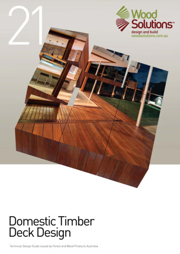
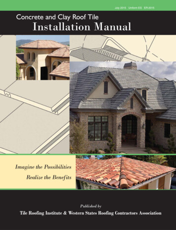
TYPICAL TRUSS LAYOUT AND TRUSS TYPES (Note: bracing not shown for clarity)Component to creategable-end verge.Creates roof plane byscotching over main trusses.Girder truss that supports hip-end trussessuch as hips and, jacks trusses.Girder truss that creates dutch hip style roofby supporting hips and, jacks trusses.Hip-end trusses that are supported bytruncated girder and creates hip plane.Truss that supports creeper trussesand creates hip roof plane.Hip-end trusses that are supportedby hip truss and creates hip plane.Truss that creates roof planes anddoes not support other trussesTruss that creates hip plane by truncating andallowing hip & jacks truss top chords to fly over.1.4.2 Hot Water ServicesHot water services are best supported directly on internalwalls, but where this is not possible, and the trusses arerequired to carry this load, then the truss manufacturermust be consulted for special designTRUSS TERMINOLOGY1.4 SERVICES1.4.11.4.3 Solar Hot Water ServicesFor solar powered hot water services, with internally orexternally mounted water storage tanks, refer to the trussmanufacturer for appropriate details. If the solar tank orpanels are installed on the roof, seek advice from trussmanufacturer.GeneralRoof trusses are capable of supporting service loads fromheating units, air-conditioned units, hot water service etc,provided the design takes them into account. The trussmanufacturer must be consulted for advice.If trusses require modification to accommodate theseservices, it is best practice to consult the trussmanufacturer before any alterations are made to a truss.Do not cut out any truss member without asking!Installation Guidelines for Timber Roof Trusses (to be read in conjunction with AS4440-2004) June 2015Solar hot water tank loadswould be normally reflectedon the truss layout.2
1.5 ANCILLARY TIMBERCheck that adequate ancillary timber is available whererequired (eg for temporary bracing).1.6 TRANSPORT AND STORAGEDuring transportation, in either the flat or upright positions,the trusses must be fully supported, taking care whilsttying down to avoid putting undue strain on the trussmembers. Trusses should be stored on the job site clearof the ground and kept flat to avoid distortion. All trussesshould be inspected on delivery, and any damagedtrusses reported to the truss manufacturer immediately toensure correct rectification.Trusses must be protected from weather, before and afterinstallation. Prolonged exposure to rain and sun can bedetrimental to both the timber (fungal damage, splitting,distortion etc) and nailplates (loss of embedment andcorrosion).If trusses are stored under tarpaulin or similar cover,adequate ventilation must be provided. This can beachieved by leaving the ends of the cover open to allowair to flow through freely and by spreading apart eachstack of trusses. Free air circulation will help dry out anycondensation that could accumulate under the cover.It is best practice to install roof trusses within a week ortwo prior to installation of roof cladding.1.7 SAFETYThe installation of timber roof trusses must adhere to therelevant safety work practices for the general constructionof roofs. This will require that barriers or safety lines beinstalled at the appropriate time. These systems must notmodify the trusses, not put loads onto the trusses, unlessprior written approval is provided by the trussmanufacturer.Section 8.5 of the Safe Work Australia publication,“Preventing Falls in Housing Construction – Code ofPractice – July 2012” provides good guidance on safeerection methods for roof trusses. It is recommended thatthe requirements in this Code of Practice are wellunderstood by the installer prior to erecting trusses.Under the heading SAFE ERECTION METHODS FORROOF TRUSSES, this Safe Work Australia publicationprovides strict guidelines for a person erecting trusses. Itstates that at no time is any person to stand on or workfrom an external wall top plate without suitable fallprotection. Below is an extract from this publication:The erection of trusses may be undertaken from internalwall top plates or from scaffold planks supported oninternal wall top plates provided: no person works closer than 1.5 metres to anexternal wall, including gable end walls no person is exposed to the risk of a fall into astairwell or other void planks are adequately supported across theirspans.The allowable spans for timber planks are given in Table1 of section 2.2 Appendix B of “Preventing Falls inHousing Construction – Code of Practice – July 2012”.Laminated timber, aluminium and steel planks must beused in accordance with the manufacturer’s directions.When trusses are erected at up to 600 mm centres,persons working between the trusses to fix or brace themcan use the erected trusses as a form of fall protectionunder controlled conditions as described below. If trussesare erected at greater than 600 mm centres, refer toSection 8.5 of this Code of Practice for suggestedmethods of working safely at heights.Truss bottom chords are considered a safe working areafor a competent person if all the conditions below are met.If the person erecting trusses is to walk or work from thebottom chords of the trusses, you should ensure that: trusses are adequately braced to stabilise thestructure. If the bottom chord is used to support theperson erecting trusses, then it should be laterallyrestrained by ties at a maximum 3000mm centres(refer Section 3.6.2 for more details) only a competent person works at heights suitable footwear that provides good foothold isworn a nominated competent person from the trusserection team oversees the work acompetentpersonorthetrussmanufacturer/supplier has provided the necessarydetail and instructions, including advice in regard toinstallers standing on the bottom chord the bottom chord is visually checked by anominated competent person for defects that maycompromise the material’s structural integrity (i.e.knots, splits, cracks and rotting timber) beforewalking on it.1.8 ROOF ANCHORS & GUARDRAILSRoof trusses are not normally designed to resist loadingfrom roof anchors or guardrails. Seek advice from thetruss manufacturer. Safety anchor requirements (typeand location) should be determined and given to the trussmanufacturer before the detailed design of trussesoccurs.Read Pryda Technical Update TU26 for further information onupgrading trusses to receive guardrail posts.Installation Guidelines for Timber Roof Trusses (to be read in conjunction with AS4440-2004) June 20153
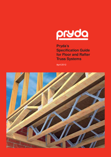
1.9 TRUSS MODIFICATIONS OR REPAIRTrusses must not be modified on site without theprior written approval from the truss manufacturer.The installer must report any damage, alterations orinstallation errors to the truss manufacturer immediatelyand must not attempt to repair a truss without arectification detail from the truss manufacturer.It must be noted that trusses and the type of damagecould vary immensely, and each repair should be treatedon its merits. The truss installer must refrain from usinghis prior knowledge or any ‘standard’ detail that he mighthave.1.10CONSTRUCTION LOADSExtreme caution must be demonstrated when placingconstruction loads on roof trusses. Stack only reasonableamount of materials, by ensuring they are located alongexternal supports or directly over internal supports of aproperly braced structure. Construction materials mustnot be placed at locations that will produce instability suchas ends of cantilevers or girder to girder connections, andshould not be dropped on trusses.Failure to heed these recommendations could result inbodily injury and/or property damage.SECTION 22.1SUPPORTING STRUCTUREGENERALTo ensure a satisfactory roof line on completion, thesupporting structure must be plumb, and the load bearingtop plates are level across the building. This will ensuresupport heights are maintained level, and consequently alevel ceiling line is achieved.Care must be taken to ensure that the supportingstructure (walls, beams etc) is adequately designed andstable in its own right.All trusses are to be fixed to the supporting structure withappropriate fixings, typically Pryda Multigrips, etc. Theselection of the fixing depends on the magnitude of thesupport reaction (uplift) and the nature of the support.Refer to Section 5 for details.COMMON PRYDA TIE-DOWN CONNECTORS2.2LOAD-BEARING WALLSThis is where the full load from the roof trusses issupported on walls - generally the exterior perimeterwalls, but may occasionally also include some internalwalls (eg: multiple span trusses)Internal Support Walls - If internal walls are required assupports, the truss itself and the layout shall bemarked accordingly, and this intention must be madevery clear. The installer shall ensure that trusses areorientated correctly when using internal walls as supports.The supporting structure, including footings, should bechecked by the builder to allow for this load.Note: If the trusses were inadvertently provided a camber at theinternal support locations, it is necessary to pack under the trussBC to ensure full bearing, prior to loading.Refer to AS1684 –2010 “Residential Timber-framedConstruction” for the wall plate, stud and lintel installationdetails.Heavy, concentrated loads such as from girders andtruncated girders are best supported directly over studs,with special attention given to the load path all the waydown the structure to the foundations.2.2.1Lintels and Support BeamsLintels and support beams must be correctly sized andsupported in order to limit deflection, and to ensure a levelbearing surface is provided for the roof trusses in the longterm.2.3NON-LOAD-BEARING WALLSNon-load-bearing walls shall not carry any truss loadingat any time, and shall not be packed to touch theunderside of the truss. It is common to set non-loadbearing walls lower than the supporting walls by anamount equal to the depth of the ceiling battens plus10mm. The truss is still required to stabilize the top of thewall, and this is done by using Pryda Partition Hitcheswhich are nailed near the top of the vertical slots. Do notembed the nail heads fully home, as the truss must beallowed to settle downwards as time passes and thecamber comes out of the truss.LOADBEARING AND NON-LOADBEARING WALLSInstallation Guidelines for Timber Roof Trusses (to be read in conjunction with AS4440-2004) June 20154
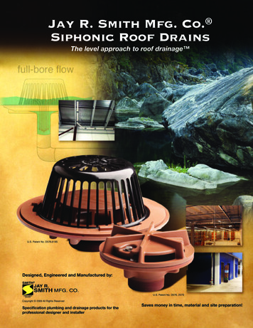
2.3.1 Fixing top plates to truss bottom chords of nonloadbearing wallsa) Bracing wallPryda Shear Connectors are used totransfer racking loads from trussbottom chords to the bracing walls.3.3LIFTINGTrusses must always be lifted in a manner that minimiseslateral bending stresses. It is preferable that they be keptstrapped in bundles until they are erected, as this reducesthe chances of damage.b) Non-bracing wallPryda Hitch Brackets are used to stabilize the top of non-loadbearing internal walls, required at 1800mm c/c. They are fixed to thetruss bottom chords through slotted holes which allow verticalmovement of trusses.Trusses may be lifted either by crane, or manually. Thechoice will depend on the truss weight and wall height.They should be maintained in a vertical plane as much aspossible when being handled individually.Trusses lifted by crane require slings or spreader bars asshown in the diagrams. Where trusses are place inbundles directly onto the top plate, it is imperative thatthey are supported by internal walls and that thesupporting structure is stable in it’s own right.SECTION 3TRUSS INSTALLATIONCraneCrane3.1GENERALThe following recommendations are guidelines only, asthe details are the responsibility of the roof truss installers.Refer to AS4440-2004 for greater detail.3.2SET OUTPrior to lifting any truss into place, it is often convenient tomark out the truss locations on the top plate, using thesupplied truss layout for reference.Girder and truncated girder trusses should be set out firstas they have specific, fixed locations. Dual purposetrusses such as truncated girder / girders need specialattention as they may appear similar to other trusseswhich must not be used accidentally instead.Standard trusses must then be set out, taking care not toexceed the design spacing. Generally they would beevenly set out over runs of similar trusses. But it is alsoacceptable to space them at the design spacing and havea closing gap smaller than this - adjacent to a moreheavily loaded truss, if possible.A gauging rod is very useful for setting out trusses. PrydaTruss Spacers may also be used for this purpose.VERTICAL LIFTING OF TRUSSES – SPAN LESS THAN 9mCraneChain for brace on lateralmovement of trussCraneVertical chainor slingVERTICAL LIFTING OF TRUSSES – SPAN FROM 9m TO 16mCraneHORIZONTAL LIFTING OF TRUSSESWhen erected manually, they may be slid flat over theside walls on skids spread at 3m intervals, then rotatedInstallation Guidelines for Timber Roof Trusses (to be read in conjunction with AS4440-2004) June 20155
vertically into position – supported at the apex and panelpoints to ensure that they do not distort or sag betweensupports during this process.When positioning multiple span or cantilever trusses,take care that they are the correct way around. Suchtrusses will have markings on the bottom chordshowing the point of internal support.Also refer to Section 8.5 of the Safe Work Australiapublication, “Preventing Falls in Housing Construction –Code of Practice – July 2012” for safety aspects whenlifting trusses3.4FIRST TRUSSSome gable end trusses are designed to sit on the endwall. In these cases, it must be supported at every bottomchord panel point along its length, as it cannot act as aclear span truss.3.4.2Hip and Dutch gable roofsOn hip and Dutch gable roofs, start with the truncatedgirder, apex girder or Dutch hip girder truss and brace itback to the corner of the building as shown. It is importantthat this truss be correctly plumbed and aligned, as othertrusses must fit exactly up against it.Where it is not feasible to install bracing of the first trussin the manner described, the first two or three trussescan be erected and cross-braced between them to forma stable unit.3.4.1Gable roofsOn gable roofs, start with the gable truss which is locatedover or just inside the end wall. Then brace it back to theground, or to some other stable part of the structure.TEMPORARY BRACING FOR HIP OR DUTCH-HIP END ROOF3.5SUBSEQUENT TRUSSESAs each truss is installed, fix it to the top plate at therequired location, usually indicated by set-out marks, orby using a set-out rule. Use a gauging rod and ties forspacing the trusses, and a string line along the apex toensure correct alignment.TEMPORARY BRACING FOR GABLE END ROOFMETHOD 1 – POST WALL FRAMEIt is important that trusses are lined up along the apex, notthe heels.Any multi-ply truss must be fixed together prior tobeing installed. If the truss manufacturer has notdone this at the factory, it is his responsibility tosupply the fixing information, and the erecting crew’sresponsibility to ensure that this fixing is properlycarried out.TEMPORARY BRACING FOR GABLE END ROOFMETHOD 2 – PROP TO GROUND3.6ERECTION BRACING AND TOLERANCESAs the trusses are erected, they must be bracedlongitudinally. This is to provide stability to the trussesduring the erection process, and the bottom chord tiesshould be maintained in place after full installation iscompleted.Installation Guidelines for Timber Roof Trusses (to be read in conjunction with AS4440-2004) June 20156
However, the temporary top chord ties may be removedonce the roof battens are adequately fixed in place.Refer to AS 4440-2004 for the full details for temporarybracing, however the following is a brief summary.Temp braces on TC ateach panel point(max. 3000mm apart)TYPICAL TEMPORARY BRACING3.6.1Temp braces on BC atevery mid-panel (max.3000mm spacing)Top chordsTemporary braces at each top chord panel point.(maximum 3000 mm apart).50 x 25 F5 or MGP10 for heavy roofs (eg: tiled)70x35 F5 or MGP10 for light roofs (eg: sheet steel)3.6.2Bottom chordsTemporary braces at all mid-panels (maximum 3000mmapart), but not required for creepers, jacks, hip trusses,Dutch hip girders and TG trusses with stations up to3600mm. Use 70 x 35 F5 or better, fixed with 2/65 nailsor 1/65 screw per truss crossing.Where the bottom chord is not laterally restrained by theceiling, or by battens, ie exposed trusses or suspendedceiling, then the truss designer’s requirements must bestrictly followed.3.6.3TolerancesTrusses shall be installed straight and vertical and in theircorrect positions.Bow – trusses shall be installed with bow not exceedingthe smaller of span/200 nor 50mm.Plumb – trussesshall be installed sothat no part of thetruss is out ofplumb by morethan the smaller orheight/50 or 50mm.These tolerances will produce a good roof line, and theperformance of the trusses will deteriorate rapidly if theseare exceeded, producing excess deflections andoverstress in the truss.SECTION 4ROOF BRACING4.1GENERALThe following recommendations allow for bracing of theroof system only and assume that the walls are stable intheir own right.Bracing to the trusses is essential to prevent buckling ofmembers (chords and some webs), and to provide overallstability to the roof under all relevant loading conditions,including wind uplift where members may reverse frombeing in tension to being in compression.Care should be taken to ensure that all supportingstructure bracing is in place prior to the trusses beinginstalled.4.2BATTENSThe bracing of top chords is achieved via the overlyingbattens or purlins. Battens are to be nailed to both outerlaminates of any multiple ply trusses eg. double girders.Splice locations are restricted: Not more than one third of the battens should bespliced at a single truss, and there must not be twosplices adjacent to each other at any truss. Areas in the vicinity of the ends of gable roofs, shouldbe as free of splices as practical. Splices are not permitted at girder trusses unlessapproved by the truss manufacturer in writing. Thisrestriction does not apply to truncated girder trusses,nor to girder trusses that are designed to have roofplane bracing independent of the battens. Battens fixed to multi-ply girder trusses must benailed into each outer ply forming the girder trussassembly.Note: For battens in sheet roofs, provide special splice detailsas recommended by Pryda (refer Technical Update TU12)Installation Guidelines for Timber Roof Trusses (to be read in conjunction with AS4440-2004) June 20157
TYPICAL BRACING LAYOUT4.3TOP CHORDSAll trussed roofs require diagonal bracing to the topchords, which is typically at an angle of 30-45 degrees tothe ridge line, measured on plan. Braces should beinstalled such that each main truss has a brace on it.Bracing is best located near the ends of buildings, and willbe installed on both sides of the ridge line. Some typicalexamples are shown here, but full details are given inAS4440-2004.END FIXING DETAILS FOR STEEL BEAMGirder trussesTwo nails totop chordTwo nails to top oftruss and three to sideAnchorage pointStandard trusses4.3.1SpeedBraceThe bracing shown here is Pryda Speedbrace which hasbeen specifically designed for this purpose and should befixed with 35x3.15 Pryda Timber Connector nails.Truss bootEND FIXING DETAILS AT HEEL - TO GIRDER TRUSSEND FIXING DETAILS AT APEXPryda Speedbrace(ii) Lap SpliceTYPICAL SPLICE DETAILSEND FIXING DETAILS AT HEEL – TO TOP PLATECANTILEVERS(i) Wrapped Around SpliceFIXING DETAILS FOR BRICK-WALL PLATEInstallation Guidelines for Timber Roof Trusses (to be read in conjunction with AS4440-2004) June 20158
4.3.2CantileversIt is essential that the force in the top chord bracing betransferred to the supporting structure. In cantilevertrusses, this is achieved through the use of special detailsas shown in the diagrams.Refer to AS4440 forend fixing detailsTimber block of similar size to truss topchord fitted tightly between trusses. Usetwo nails to fix to each truss and threenails to fix to top plateSpeedbrace continuesto truss heelTwo nails totop chord90x35 F5 minimum timber blockfixed in line with the bottom ofbottom chord fitted tightlybetween trusses usingmultigrips as shown.TYPICAL WEB BRACING AND FIXING DETAILSRefer to AS4440 forend fixing detailsFIXING DETAILS FOR CANTILEVERSRefer to AS4440 forfixing to brick wall plateIn addition to web ties, Pryda Web Stiffener, TeeStiffeners or scabs may be also designed to brace webs4.4BOTTOM CHORDSGenerally ceiling battens or ceiling fixed directly to theunderside of the bottom chords is sufficient to providelateral restraint against buckling.PRYDA WEB STIFFENERTee stiffener (min 90x35 MGP10) fixed toweb using 3.15 dia x 65 nails at 200 c/cBottom chord ties, when used as lateral restraints, shouldbe fixed adequately to the supporting structure andbraced.a) For trusses over 12m span, or trusses where there isno ceiling, additional bottom chord bracing will berequired.b) Additional bottom chord bracing or a wind truss mayalso be required where the ceiling diaphragm isconsidered to be incapable of transferring rackingloads to braced walls.c) Additional bottom chord ties and bracing are requiredwhen ceiling is connected through metal furringchannels that are only clipped onto the bottom chord.The truss layout should indicate details of this.WebTIMBER TEE-STIFFENER4.5.2End websAll trusses with end vertical webs not intersecting withanother truss, will need end web bracing similar to the topchord bracing. Diagonal bracing from the top chord to thesupporting structure should be provided at each end ofeach run of trusses as shown.90x35 F5 minimum timber block fixedin line with the top of top chord fittedtightly between trusses usingmultigrips as shown.Bend Speedbrace overtimber block and fixedwith five nailsIn each of these cases, the requirement must be checkedby an experienced truss designer, and the detailssupplied by the truss manufacturer.4.5WEBS4.5.1Long websSome webs must be braced if required by the trussdesigner. Generally this applies to long webs which are incompression during some part of the life of the structure.Typically this is a 70x35 F5 or MGP10 web tie locatedmid-length of the web. By itself it does nothing, so theseweb ties must be cross-braced back to part of thestructure that can provide adequate resistance.Bracing angle to bebetween 30 deg and45 degBend speedbrace to side of topplate and under (if necessary).Fix with five nails to top plate.Nails shall be not closer than10mm to the edge of the timberRefer to AS4440 forfixing to brick wall plateFIXING DETAILS FOR ENDS OF CUT-OFF OR MONO TRUSSESTYPE ENDSInstallation Guidelines for Timber Roof Trusses (to be read in conjunction with AS4440-2004) June 20159
Timber blocksfixed in line withthe chords fittedtightly betweentrusses.Top chord – one Pryda multigrip bent tosuit, with 3.15 x 35mm Pryda Connectornails into the side of each top chord fortruncated girderFixing details to besimilar to the end of cutoff or mono trusses4.6FIXING DETAILS AT BOX GUTTER TYPE ENDSTop Hat ConstructionBottom chord – three effective flat-head65mm nails.Top chord – one Pryda multigrip bent tosuit, with 3.15 x 35mm Pryda Connectornails into the side of each top chord fortruncated girderTruss manufacturers may choose to form a truss in twosegments, Top Hat Construction, often dictated bymanufacturing or transportation restrictions. This form ofconstruction requires special consideration, especiallybracing and lateral restraints for horizontal top chord ofthe lower truss. Obtain further details from your trussmanufacturer.Top hat trussesBottom chord – three effective flat-head65mm nails each side of jack truss.Two 65mm skew nails into the side ofeach top chord.Top chord – three effective flat-head65mm nails through jack truss topchord into hip truss top chord.TOP HAT CONSTRUCTIONSECTION 5Bottom chord – three effective flat-head65mm nails through jack truss bottomchord into hip truss bottom chord.TRUSS CONNECTIONS5.1HIP ENDSThe details shown here are for a maximum design windof 50 m/sec (non-cyclonic). Refer to AS 4440-2004 for fulldetails including up to 74 m/sec cyclonic.The hip end connections provided by Pryda Buildsoftware are similar to those in AS4440-2004, but theymay not be exactly the same, as every connection isdesigned specifically for the conditions at each site.The requirements called up by Pryda Build takeprecedence over AS4440 or any other guideline. Adocument (Software Update No. 7) is available to produceto certifiers if required.Top chord – three effective flat-head65mm nails through jack truss topchord into hip truss top chord PLUSone mitre plate with 3.15 x 35mmPryda Connector nails to each chordBottom chord – three effective flat-head65mm nails through jack truss bottomchord into hip truss bottom chord.CONNECTION DETAILS – HIP-END TRUSSES FORWIND CLASSIFICATION N1, N2, N3 OR C1(Refer AS4440 for details in N4, C2 or C3)Installation Guidelines for Timber Roof Trusses (to be read in conjunction with AS4440-2004) June 201510
5.2GIRDERSWhere a girder truss is utilised to support the standardtrusses perpendicular to it, they must be connected to thegirder with special devices which:a)Support the loadsb)Prevent separation of the girder bottom chord awayfrom the standard trussesc)Prevent rotational force being applied to thestandard truss.5.4VALLEYSWhere overlying members sit on the top chord of a truss,the nominated top chord restraint must still be maintained.This can be achieved with careful detailing as shown here.FIXING DETAILS FOR VALLEY TRUSSESSTANDARD TRUSS BOOT AND ANTI-TWIST BAR5.2.1Main girdersStandard trusses may be fixed to the girder truss by Prydaproducts. The truss manufacturer will generally supplythe appropriate bracket for each connection, or otherwisespecify.It is important to fix the truss boot properly,i.e including fixing to incoming trusses, prior to roofbeing loaded. Otherwise bottom chord rotation can occur.5.5OVERHANGSIt is important that overhangs are supported as intendedby the truss designer. Refer to AS4440-2004 for fulldetails.5.5.1Strutted Overhangs (Boxed Eaves)Strutted overhangHeavy Duty Truss BootStandard Truss Boot5.2.2Dutch Hip GirdersThe waling plate must be fixed to the Dutch Hip girder trussin accordance with the details supplied by the truss manufacturer.Refer to truss layout or detailsheet for fixing requirements,using nails or screws (typical)Struts at hip corners and other areas must be fixed inaccordance with the details supplied by the trussmanufacturer.5.5.2Verge OverhangsWaling PlateDUTCH HIP GIRDER FITTED WITH WALING PLATEOUTRIGGERS5.3GABLE-END TRUSSESSpecial care shall be taken to ensure face wind loads fromend wall are not applied directly on the gable-end truss.Refer to Pryda’s publication on Gable-end Framing forfurther details.ZED SPROCKETS
All trusses are to be fixed to the supporting structure with appropriate fixings, typically Pryda Multigrips, etc. The selection of the fixing depends on the magnitude of the support reaction (uplift) and the nature of the support. Refer to Section 5 for details. 2.2 LOAD-BEARING WALLS This is where the full load from the roof trusses is