Transcription
INSTALLATIONMANUALDOWNFLOW/UPFLOWELECTRIC FURNACEMODELS: EB SERIESTABLE OF CONTENTSGENERAL INFORMATION . . . . . . . . . . . . . . . . . . 2EB FURNACE NOTES . . . . . . . . . . . . . . . . . . . . . . . 2CODES . . . . . . . . . . . . . . . . . . . . . . . . . . . . . . . . . . . 2LOCATION . . . . . . . . . . . . . . . . . . . . . . . . . . . . . . . . 2FURNACE CLEARANCE . . . . . . . . . . . . . . . . . . . . . 2RETURN AIR . . . . . . . . . . . . . . . . . . . . . . . . . . . . . . 2DUCT SYSTEM DESIGN . . . . . . . . . . . . . . . . . . . . . 3DOWNFLOW FURNACE INSTALLATION(WITH 7900 SERIES DUCT CONNECTOR) . . . . . . 3DUCT CONNECTORS (7990 SERIES) . . . . . . . . . . 4INSTALLATION OF SCREW ATTACHMENT DUCTCONNECTOR (7990 SERIES) . . . . . . . . . . . . . . . . . 5INSTALLATION OF TAB ATTACHMENT DUCTCONNECTOR (7990 SERIES) . . . . . . . . . . . . . . . . . 5INSTALLATION OF THE FURNACE . . . . . . . . . . . . 6FURNACE CONVERSION TO UPFLOWAPPLICATION . . . . . . . . . . . . . . . . . . . . . . . . . . . . . 6WIRING . . . . . . . . . . . . . . . . . . . . . . . . . . . . . . . . . . 7THERMOSTAT INSTALLATION . . . . . . . . . . . . . . 9OPTIONAL AIR CONDITIONINGACCESSORIES . . . . . . . . . . . . . . . . . . . . . . . . . . 10HIGH PERFORMANCE BLOWER ACCESSORYPACKAGE . . . . . . . . . . . . . . . . . . . . . . . . . . . . . . . 11WIRING DIAGRAMS . . . . . . . . . . . . . . . . . . . . . . 11REPAIR PARTS LIST . . . . . . . . . . . . . . . . . . . . . 17CAUTION: READ ALL SAFETY GUIDESBEFORE YOU START TO INSTALLYOUR UNIT.SAVE THIS MANUALIncorrect installation may create conditionwhere the operation of the product couldcause personal injury or property damage.The furnace shall be installed so the electrical components are protected from water.This product must be installed in strictcompliance with the enclosed installationinstructions and any applicable Local, Stateand National Codes including, but not limited to building, electrical, and mechanicalcodes. Improper installation will void thewarranty.66669035-15266-003 Rev. A (0804)
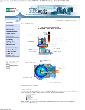
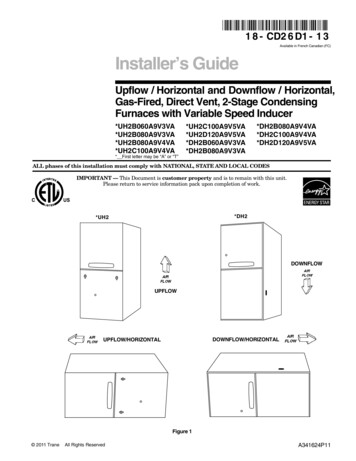
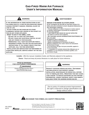
035-15266-003 Rev. A (0804)GENERAL INFORMATIONCODESEB FURNACE NOTESThe electric furnace must be installed in accordance with thefollowing codes:The following list includes important facts and informationregarding the EB furnace and its packaging inclusions:1.Furnace is rated at 240 volts, 60 Hz, single phase.2.Heating and Cooling thermostat is packed with furnace.3.Filters are furnished with each model.4.Filter size is universal to all models - 16 x 20 x 1. Standard for the Installation of Air Conditioning and Ventilating Systems (NFPA 90A)Standard for the Installation of Warm Air Heating and AirConditioning Systems (NFPA 90B)National Electric Code (NFPA 70)Canadian Electrical Code, Part I (CSA C22.1)All local codes (state/county/township).NOTE: All applicable codes take precedence over any rec19-5/8SUB-BASE, IF USED,ADDS 7/8” MORE TOTOTAL HEIGHT AND3/8” TO 7/1616-1/2LMFURNACE CLEARANCEElectric furnace is approved for zero (0) in. clearance to combustible material on all or any part of the furnace exterior andthe inlet or outlet duct work. Clearances must be providedabove the furnace for a minimum of 200 sq. inches free opening for return air. For clearances other than shown above seeparagraph on Return Air.FOR HEATING ONLY FURNACEOPTIONAL BOTTOM FIELDWIRING ENTRYJHAAccess for servicing is an important factor in the location ofany furnace. Provide a minimum of 24 inches in front of thefurnace for access to the heating elements and controls. Thisaccess may be provided by a closet door or by locating thefurnace 24 inches from a facing wall or partition.In order for the furnace to work properly, a closet or alcovemust have a certain total free area opening for return air.KBLOCATIONRETURN AIRNFIELDWIRINGENTRYCommendation made in these instructions.EDF GMinimum 200 in2 free area opening.Use Return Grille 7900-287P/B,Or any Return Grille with minimum 200 in2 free area opening.FOR A/C UP TO 4-TONS AND HP UP TO 3 1/2-TONSFIGURE 1 : FURNACE DIMENSIONS5.Furnace size is the same for all models. See Figure 1.6.Four-wire thermostat operation for heating and cooling.7.Coil cavity built into furnace.8.All furnaces are equipped with an air conditioner blowerand is A/C or Heat Pump ready.9.Holding strap furnished on top rear of furnace.10. This furnace is designed for downflow application; however, it may be converted to an upflow application. (SeePage 6 for upflow conversion instruction.)11. This furnace must not be operated without the frontpanel installed.NOTE: This furnace and its components listed on the A/Cand Heat Pump equipment sticker were listed incombination as a system by Underwriter's Laboratories for the United States and Canada.2Minimum 250 in2 free area opening.Use Return Grille 7900-287P/B, 1FG0620BK (hinged),Or Louvered Door 3500-1581, 3500-5851 (bulk pack),Or any Return Grille with minimum 250 in2 free area opening.FOR A/C UP TO 5-TONS AND HP UP TO 4-TONSMinimum 330 in2 free area opening.Use Return Grille 1RF1025BK, 1FG0125 (hinged),Or Louvered Door 3500-1591, 3500-5861 (bulk pack),Or any Return Grille with minimum 330 in2 free area opening.The return air opening can be located in a closet front door ora sidewall above the furnace casing, or in a louvered door onthe furnace. If opening for the return air is located in the floor,side walls or closet door anywhere below furnace casingheight, 6 inches minimum clearance must be provided on thefurnace side where return is located to provide for proper airflow. See Figure 2. The 6 “ minimum clearance is not requiredif there is a return grille installed above the furnace height.This return grille cannot start more than three feet above thefurnace height.Unitary Products Group
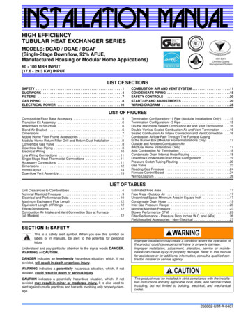
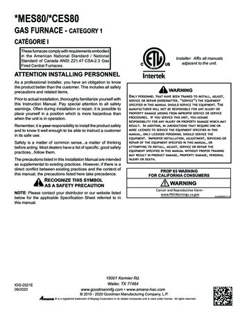
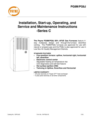
035-15266-003 Rev. A (0804)DUCT SYSTEM DESIGNThere must be at least2 ft. of space availablein front of furnace forservicing the furnacewhen necessary.23” MIN.Electric furnace is designed to operate at a given static pressure.In order to assure proper air flow through the furnace, the distribution system must be designed so that the static pressureexternal to the furnace does not exceed the static pressurerating shown on the furnace rating plate. See Table 3.The number, size and placement of registers should be suchthat even distribution of heat is provided throughout thehome.20”A 6 in. clearance isrequired if the spacebetween furnace andenclosure is used forreturn air.24” MIN.DOWNFLOW FURNACE INSTALLATION(WITH 7900 SERIES DUCT CONNECTOR)We have redesigned our duct connector to eliminate the subbase requirement. Table 1 will help you in deciding the partnumber of the new duct connector you need.If you are installing a new duct connector (7900 Series), referto the following instructions. Read carefully the instructionsprovided before starting the installation.20”Provide adequate clearance for servicing.FIGURE 2 : ALCOVE & CLOSET CLEARANCESFor Upflow installations, a closet 32 inches wide by 30 inchesdeep with a 30-inch wide door is necessary. See Figure 3.When installing furnace in a separate closet or room which isaccessible only through an outside door, a minimum of 200sq. in. free opening for return air must be provided. The supply and return air must be ducted, securely attached and besealed to the furnace casing if there are grilles in the outsidedoor to the closet. Openings where ducts pass through walls,the floor or the ceiling must be sealed to prevent air leakageinto or from closet and the living area.32”1-5/8” MIN., 2-3/8 MAX.30”RETURN AIRPASS THROUGHFRAME WIDTH30”WIDE DOOR25-1/2””CLOSETFIGURE 3 : UPFLOW CLOSET CLEARANCEProvisions shall be made to permit the return of circulating airfrom all rooms and living spaces, except the bathroom(s) tothe circulating air supply inlet of the furnace. Failure to comply may cause improper heating and may cause the furnaceto cycle on the limit.Unitary Products Group1.Locate furnace conveniently away from wall facing orpartitions to permit easy removal of components.2.A minimum of six (6) inches should be maintainedbetween the furnace and closet door when door is usedfor return air. See Figure 2.3.Two (2) feet of space must be available in front of furnace for future servicing (blower or element removal, furnace removal, etc.).Table 1: DUCT CONNECTOR FOR ELECTRICFURNACESFLOOR TODUCT DIMENSIONSFINGEREDSTYLESCREWTAB ” 4”7990-62417990-60415” 90-62817990-60819” 10”7990-63017990-610111” 12”7990-63217990-612113” 14”NANA15”NANA - Indicates connector above or below could be useddepending on tolerance in floor to duct dimension. - Indicates connector above could be used dependingon tolerance in floor to duct dimension. - Indicates connector below could be used dependingon tolerance in floor to duct dimension.3
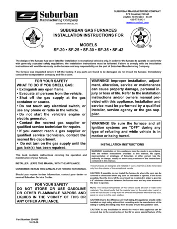
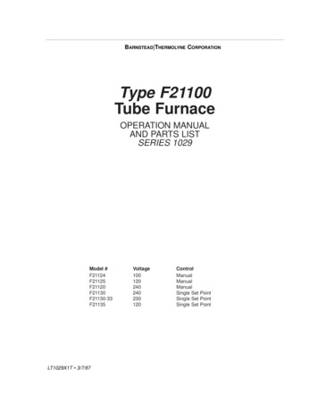
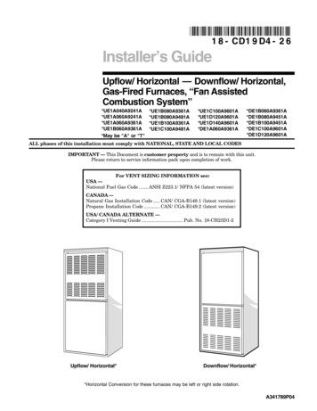
035-15266-003 Rev. A (0804)DUCT CONNECTORS (7990 SERIES)These duct connectors are for connecting the furnace to an under the floor supply duct system.The furnace may be installed on combustible flooring without a separate sub-base.DUCT CONNECTORS FORSCREW ATTACHMENT18 3414238238SEECHART238DUCT CONNECTORS FORTAB ATTACHMENT318 318 44381218 34438FIGURE 4 : DUCT CONNECTOR DIMENSIONS (7990 SERIES) REAR WALLOF ENCLOSURE2-3/4MIN.CEILING CUT-OUTFOR ROOF JACKFLOOR CUT-OUTFOR DUCTCONNECTOR9-7/8FLOORFLOORJOISTDUCT ALELECTRICENTRANCE2-1/81-3/8SUPPLY DUCT1-1/86-3/83-1/419-3/420FLOORFUTURE REFRIGERANTLINE ENTRANCEFIGURE 5 : RECOMMENDED FLOOR CUT-OUT (7990SERIES)4FIGURE 6 : DUCT CONNECTOR DEPTH(7990 SERIES)Unitary Products Group
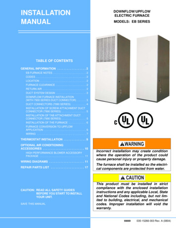
035-15266-003 Rev. A (0804)LOCATOR BRACKETLOCATOR BRACKETNAILS, FLAT HEAD SCREWSOR STAPLESBEND TABS UNDERDUCT OPENING TOSECURE TO THESUPPLY DUCT.NAILS, FLAT HEAD SCREWSOR STAPLESSCREWSFLOORFLOORSUPPLY DUCTFIGURE 7 : DUCT CONNECTOR SCREWSUPPLY DUCTFIGURE 8 : DUCT CONNECTOR TABATTACHMENT (7990 SERIES)ATTACHMENT (7990 SERIES)INSTALLATION OF SCREW ATTACHMENT DUCTCONNECTOR (7990 SERIES)INSTALLATION OF TAB ATTACHMENT DUCTCONNECTOR (7990 SERIES)1.Make floor cut out as shown in Figure 5.1.Make floor cut out as shown in Figure 5.2.Determine the depth of the floor cavity from the surfaceof the floor to the top of the supply air duct and select theappropriate duct connector from the chart.2.Determine the depth of the floor cavity from the surfaceof the floor to the top of the supply air duct and select theappropriate duct connector from the chart.3.Place locating bracket (supplied with the duct connector)to the back edge of the floor opening. See Figure 7.3.Place locating bracket (supplied with the duct connector)to the rear of the floor area for the furnace. See Figure 8.4.Apply a water based duct sealant to the 1/2" supply ductattachment flange of the duct connector.4.5.Determine which of the four positions the duct connectorbest centers over the supply duct and insert it throughthe floor cutout.Determine which of the four positions the duct connectorbest centers over the supply duct and insert it throughthe floor cutout.5.Mark cut-out location on the supply duct and remove theduct connector.6.Cut out the opening to the supply duct.7.Bend tabs down through and back up under the supplyduct.8.Secure the duct connector to the floor with nails, flathead screws or staples.6.When properly aligned with the supply duct, secure theduct connector to the floor with nails, flat head screws orstaples.7.Use screws as required to secure the duct connector tothe supply duct.8.Cut out the opening to the supply duct. If sealant was notused, the installer should tape the mating flanges to provide a good air seal.NOTE: Duct sealant and tape must be classified as meetingHUD Standard 3280.715, U.L. Standard 181A. Tapeused to provide a better air seal should be approvedby the applicable National or Local Code.Unitary Products GroupThe duct connector is designed for use on ducts down to 12"in width. When using the connector on smaller width ducts,there will not be sufficient clearance to bend the tabs on twosides of the duct connector.In such cases the tabs may be attached to the sides of theduct by using sheet metal screws or other suitable fasteners.Holes for sheet metal screws are provided in three (3) tabs oneach side of the duct connector. If more than 3 tabs need tobe used to provide a more secure and air tight connection,the remaining tabs can also be fastened to the duct withscrews after drilling the required screw holes.5
035-15266-003 Rev. A (0804)PARALLEL DUCT SYSTEMThe EB Duct Connector Insert 37323716001 may be used onEB Series Electric Manufactured Housing Furnaces wherethe duct system runs parallel to the furnace. See Figure 9.The EB Duct Connector Insert should not be used if the ductsystem runs perpendicular to the furnace or if the duct system extends only one direction from the furnace.The Duct Connector Insert cannot be used with 1” and 2”Duct Connectors (7990-6011, 7990-6021, 7990-6211, and7990-6221).Follow Accessory Kit Installation Instruction 035-20632-001provided with the Duct Connector Insert.FURNACE DOORFURNACE DOORPERPENDICULAR LAYOUTFURNACE CONVERSION TO UPFLOWAPPLICATIONUpflow furnace conversion is easily accomplished by following the steps listed below:Provide adequate clearance for servicing:1.Before Conversion, locate the furnace convenientlyaway from wall facing or partitions to permit easyremoval and installation of components.2.Two (2) feet of space must be available in front of furnace for future servicing (blower or element removal, furnace removal, etc.).3500-5451* Adapter Box and/or 3500-7211* Upflow FlangePlate Kit are needed prior to following steps below:1.Assemble the 3500-5451 filter box per installation provided with kit.2.Remove furnace panel.3.Remove air filter.4.Remove strap on the top of the unit, saving the screwand strap for later use.5.Turn entire unit upside-down, so the filter box is on thefloor.6.Remove two (2) screws that are on the front of the unit atthe top. Obtain front panel hanger angle from the upflowkit 3500-7211*. Secure the hanger angle with two (2)screws removed from the furance casing See Figure 11.PARALLEL LAYOUTFIGURE 9 : DUCT SYSTEM CONFIGURATIONFURNACE SEATEDAGAINST THELOCATOR BRACKETSECURE FURNACETO FLOOR WITHTWO NAILS ORSCREWSHANGER ANGLECASINGSCREW x 2FIGURE 11 : HANGER ANGLE ATTACHMENTFIGURE 10 : INSTALLATION OF FURNACEINSTALLATION OF THE FURNACE1.Remove the front panels and set the furnace onto theduct connector. Slide it back until the rear of the unitengages the locator bracket.2.Secure the front of the furnace with two screws at themounting holes provided. See Figure 10.3.Secure the top of the furnace to a structural memberusing screw through the strap at the top of the furnace.Strap may be moved to any of the holes located alongthe top back of the furnace. Installer may provide anequivalent method, such as screws through the casingside.67.Attach the strap that was removed in Step 4 to the top,side or back of the furnace.8.Install the duct flange plate on top of the inverted furnaceas shown in Figure 12.9.If installaing POS, Standard or Deluxe Air Systems, proceed to Step 10.Optional start collar for the Economy POS systemshipped with 3500-7211* can be used for blend air flexduct installation. Punch the lineset knockout out andposition the start collar over it. Duct connector edge canbe pushed under the casing flange and screws providedcan be used to capture the other end of duct connector.Secure collar to top of furnace.Unitary Products Group
035-15266-003 Rev. A (0804)10. Flange plate shipped with 3500-7211* is mounted to thefurnace with eight (8) screws provided. Two (2) bluntscrews are for the holes in the front of the furnace. SeeFigure 12.11. If upflow adapter box kit 3500-5451* is not used, thenour optional filter bracket is provided with 3500-7211* kit.This filter bracket maybe used to retain filter inside itsoriginal location in the furnace.12. Secure the top of the furnace to a structural memberusing screws and the strap on top of the furnace. Themobile home manufacturer may provide an equivalentstrap, if required, to secure the furnace.13. If excessive movement is expected, then some blowersupport is recommended.USE BLUNTSCREWS HEREFLANGEPLATE(MOUNTED WITHSCREWS)WIRINGFurnace wiring is complete except for the power supply andthe thermostat wires. See wiring diagram (or Table 2) for wireand fuse size. See Table 2 for ground wire sizes. Thermostatwires connect through side of furnace and should also be nosmaller than 22 gauge. Power wires can enter through theside of the unit or through the auxiliary entrance, located inthe bottom of the unit. (See Figure 1). When bringing wiringthrough the bottom of the furnace, cable connectors must beinstalled to hold wiring in place and to relieve any strain onthe wiring. These connectors will also serve as a sealbetween the furnace and the floor. Thus, additional sealing isnot required.(Refer to the National Electrical Code, Canadian ElectricalCode and local codes for wiring material requirements.NOTE: The furnaces are equipped with either one or two 60amp circuit breakers. These circuit breakers protectthe wiring inside of the furnace in the event of ashort circuit. Additionally, these breakers provide ameans of disconnecting the power to the unit. Thecircuit breakers in the furnace are not meant to protect the branch circuit wiring between the furnaceand the home's breaker panel. General wire andbreaker sizes are shown in Table 2. If sheathedcable is used, refer to National Electrical Code,Canadian Electrical Code and local codes for additional requirements concerning supply circuit wiring.Electrical Data can be found in Table 4.DUCTCONNECTORLINESETKNOCKOUTEB SERIES(UPFLOWFURNACE)IMPORTANT - All installation on field wiring must berated at 60ºC or higher. Please refer to the wiring diagramson the furnace or this book for more information.FIGURE 12 : BLOWER BRACKET AND DUCT FLANGEATTACHMENTTable 2:MODELSSingle Branch Circuit Service *Nominal Circuit Load - AMPSMinimum Wire Size (90º)Minimum Wire Size (75º)Minimum Wire Size (60º)Ground Wire Size Max. Fuse (or C.B.) - AMPSDual Branch Circuit ServiceBranch Circuit Load - AMPSBranch Circuit Min. - AMPSMinimum Wire Size (90º)Minimum Wire Size (75º)Minimum Wire Size (60º)Ground Wire Size Max. Fuse (or C.B.) - AMPSEB23B94.0#2#1#0#6125CKT #1 CKT EB15B2 Leads 1 Ground T #1 CKT #2 CKT #1 CKT #2 CKT #1 CKT 0#10#10#10605060306030EB12B EB10B50.7#6#6#4#87044.0#8#6#6#1060NOTAPPROVED* Requires Jumper Bars (P/N 3500-3781*) - Dual Supply for U.S. Only.Refer to National Electrical Code. Table 310-16 for Non-Sheathed Conductors. Refer to National Electrical Code. Table 250-95 for Non-Sheathed Conductor Ground Wire.Unitary Products Group7
035-15266-003 Rev. A (0804)Table 3: EB SERIES BLOWER PERFORMANCELow SpeedHeating SpeedModels EB10, 12, 15Medium SpeedHeating SpeedModels EB17, 20, 23Medium Highwith A-Coil in placeHighwith A-Coil in placeStatic Pressure(Inches of WC).0.1.2.3.4.5.6.7.8CFM (STD. Air)945936936924915889870813705Static Pressure(Inches of WC).0.1.2.3.4.5.6.7.8CFM (STD. Air)11601145114511401129110910731027935Static Pressure(Inches of WC).0.1.2.3.4.5.6.7.8CFM (STD. Air)13401317129012521208115810951021876Static Pressure(Inches of WC).0.1.2.3.4.5.6.7.8CFM (STD. Air)157315341490143513691309123711351019Table 4: ELECTRICAL DATAMODEL 5BEB12BEB10B240 VAC60 Hz.1 19.616.415.011.410.0230 VAC60 Hz.1 17.915.213.810.69.1220 VAC60 Hz.1 16.714.112.69.78.5Element Capacity@ 240 .740.050.7*44.01Motor AMPS @ 240 V.Circuit Load AMPS@ 240 V.4.0 MaximumCKT 147.344.047.344.0CKT 246.740.023.420.01.Approved for Single Branch Circuit Service OnlyCasing or Cabinet must be Permanently Grounded in Accordance with National Electrical Code or other Applicable Codes.Models for EB23B, EB20B, EB17B and EB15B may be connected to a single or dual branch circuit. (See Table 2.)These units are shipped from the factory set up for dualpower supply connections. For single power supply connec-8tions, jumper bars (P/N 3500-378P*) are required and areavailable from the factory. Model for EB12B is factory shippedwith jumper bars in place.Unitary Products Group
035-15266-003 Rev. A (0804)SEQUENCERSCIRCUIT BREAKERSTHERMOSTATWIRES3500-378P* JUMPERBARS (FOR SINGLEBRANCH CIRCUITSERVICE)BLOWERRELAYNOTE:AS SHIPPED, THE JUMPER BARASSEMBLY IS SET-UP FORBOTTOM ENTRY. FOR SIDEENTRY, THE TOP LUG CAN BEREMOVED AND RE-POSITIONED,AS SHOWN, TO PROVIDEPROPER WIRE GSFIGURE 13 : CONTROL BOXTHERMOSTAT INSTALLATIONThe adjustable heat anticipator in the thermostat is pre-set at0.4 Amps. This setting should be checked at the time ofinstallationFor personal safety be sure to turn the electricalpower “OFF" at the household service box and atthe furnace circuit breakers before attempting anyservice or maintenance operations. Homeownersshould never perform any maintenance whichrequires opening electric box door.Furnace is equipped with a protective shield overfield wiring connection. When field wiring is completed, shield must be replaced to prevent hazard ofelectrical shock when using furnace disconnect.(See Figure 14.)In some cases the thermostat may be a “self-setting" type inwhich case no Amp. setting will be found on the thermostat,eliminating the need for any field adjustment.Thermostat should be located on an inside wall in an openarea to more closely regulate average room air, preferably,where there is air movement back to furnace. Care should beused to locate thermostat away from hot air discharge openings, lights, etc. Locating height of thermostat is important.Thermostat should be located 52 to 66 inches above thefloor. This is sometimes called the comfort zone.If a condenser with its own Transformer shares a Heat/CoolThermostat with this furnace, use a thermostat with isolatingcontacts to prevent interconnection of Class II 24 Volt Systems.Cycle furnace to make sure it will operate correctly.Maintenance and operating instructions are in the customerenvelope accompanying the furnace.Give the customer envelope to the home owner.CIRCUITBREAKERSBLOWERELECTRICPANELFIELD WIRINGPROTECTIVESHIELDFIGURE 14 : FIELD WIRING SHIELDUnitary Products Group9
035-15266-003 Rev. A (0804)COOLINGTHERMOSTATHEATINGTHERMOSTATWhen using separate thermostats, a thermostatinterlock system must be provided to prevent simultaneous operation of the furnace and air conditioner.Simultaneous operation can result in coach overheating, equipment damage and energy waste. (SeeFigures 15 and 16.)DOUBLE POLEDOUBLE THROW SWITCHDo not connect Yellow wire to thermostat until anoutdoor unit is installed.TOFURNACETOAIR CONDITIONERFIGURE 15 : THERMOSTAT WIRINGThe EB*B* Furnaces are A/C ready.All furnaces installations should include a minimum of four conductor thermostatwiring to accommodate future air conditioning installations.THERMOSTAT WIRING SCHEMATIC FOR: BLEND AIR AND FURNACEREDREDWHITEWHITEGREENGREENDELUXE BLEND NREDBLACKNOT FACTORYINSTALLEDWIRES FROM FURNACESTANDARD OR DELUXEBLEND AIR CONTROL BOXFour-conductor wire is required for thermostat connection.Attach the 4 low voltage wires extending from the control box as follows:1. RED wire from Furnace to thermostat RED wire.2. WHITE wire from Furnace to thermostat WHITE wire.3. GREEN wire from Furnace to thermostat GREEN wire.4. BLACK wire from Furnace to condensing unit contactor.5. Thermostat YELLOW wire to condensing unit contactor.FIGURE 16 : THERMOSTAT WIRINGOPTIONAL AIR CONDITIONINGACCESSORIESThis furnace is already equipped with a blower and controlsystem to add-on air conditioning up to 4 tons and heat pumpup to 3-1/2 tons. Insulation and coil shelf kit (3500-8941* fordownflow or 3500-8961* for upflow) must be installed whenadding on such remote air conditioning systems.Failure to install this insulation and coil shelf kitcould result in damage to equipment and/or personal injury. Liability and warranty from the manufacturer could also be void.10Unitary Products Group
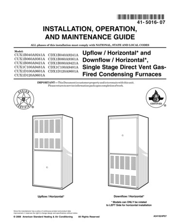
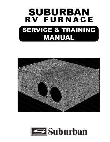
035-15266-003 Rev. A (0804)HIGH PERFORMANCE BLOWER ACCESSORYPACKAGEAll EB furnaces are already equipped with a blower and control system to add-on air conditioning up to 4-tons and heatpump up to 3 1/2-tons. If the requirement is to achieve morethan specified than the production blower inside the furnacewould have to be replaced with an accessory blower package3500-7901*. This accessory blower package would deliver airconditioning up to 5-tons, and heat pump up to 4-tons. Accessory package (3500-7901*) includes blower, insulation, coilshelf, trap, clamps, etc. Please refer to the installation instructions packed with the accessory package for more information.All areas around the line sets, drain hoses and otheropenings in the coil shelf should be sealed air tight.Use some moldable compound or caulking to sealthe area. Failure to do so may result in loss of performance and premature compressor failure.WIRING DIAGRAMSCAPACITORORG-COMMON.BLK-COOLING SP.RED-HEATING SP.REDGWRHYCOND. UNITCONTACTOR2 SPADE (INSUL.) TERMINALSUSED WHEN CHANGING 3ALOADREDBLKBLKGRNORG2HEAT/COOLT’STATBLK4-SPEED BLOWEREB SERIES FURNACESMOTORBLU-MED. HIGH SP.YEL-MED. LOW SP.BLEND AIRCONTROL BOX*GRNWHTNBR RGOBLKYELCIRCUIT #1BREAKERH2H160 AMPYELYELM3M1M4M2SEQUENCER240 VAC.60 Hz1 PHASEYELLRLRELEMENTSORGYELORGBLUGND.LUGMODEL: EB10BSINGLE BRANCHCIRCUIT SERVICELIMITSWITCHES240 VAC - 60 Hz - 1 PHASENOTE: IF ANY OF THE ORIGINAL WIRE SUPPLIEDWITH THIS UNIT MUST BE REPLACED. ITMUST BE REPLACED WITH TYPE 105 CTHERMOPLASTIC OR ITS EQUIVALENT.FACTORY WIRING SHOWN SOLID. FIELDWIRING SHOWN BROKEN.WIRING MUST CONFORM TO LOCAL CODESAPPROVED FOR CU CONDUCTORS ONLY.34,000D.O.E. OUTPUT CAPACITY - BTU4.0MAX. MOTOR-FLASINGLE BRANCH2 LEADS 1 GROUNDCIRCUIT SERVICE44.0NOMINAL CIRCUIT LOAD-AMPSWIRE SIZE (75 C) COPPER#6WIRE SIZE (60 C) COPPER#6MAX. FUSE SIZE (OR CB) - AMPS60FIGURE 17 : EB10B WIRING DIAGRAMUnitary Products Group11
035-15266-003 Rev. A (0804)CAPACITORGRNWHTORG-COMMON.YEL-MED. LOW SP.BLK-COOLING SP.RED-HEATING SP.BLU-MED. HIGH SP.BLEND AIRCONTROL BOX4-SPEED BLOWEREB SERIES FURNACESMOTORRED*BLKNBR RGOHEAT/COOLT’STATGWRHYCOND. UNITCONTACTOR2 SPADE (INSUL.) TERMINALSUSED WHEN CHANGING KCIRCUIT #1BREAKERM3M1H1M4M260 AMPYELH2REDBLKYELORGBLU60 AMPSEQUENCERYELLRLRREDELEMENTSNOTE: IF ANY OF THE ORIGINAL WIRE SUPPLIEDWITH THIS UNIT MUST BE REPLACED. ITMUST BE REPLACED WITH TYPE 105 CTHERMOPLASTIC OR ITS EQUIVALENT.FACTORY WIRING SHOWN SOLID. FIELDWIRING SHOWN BROKEN.WIRING MUST CONFORM TO LOCAL CODESAPPROVED FOR CU CONDUCTORS ONLY.JUMPER BARSBLOWERRELAYBLKORGYELLOAD240 VAC.60 Hz1 PHASECIRCUIT #2BREAKERGND.LUGMODEL: EB12BSINGLE BRANCHCIRCUIT SERVICELIMITSWITCHES240 VAC - 60 Hz - 1 PHASE39,000D.O.E. OUTPUT CAPACITY - BTU4.0MAX. MOTOR-FLASINGLE BRANCH2 LEADS 1 GROUNDCIRCUIT SERVICE50.7NOMINAL CIRCUIT LOAD-AMPSWIRE SIZE (75 C) COPPER#6WIRE SIZE (60 C) COPPER#4MAX. FUSE SIZE (OR CB) - AMPS70FIGURE 18 : EB12B WIRING DIAGRAM12Unitary Products Group
035-15266-003 Rev. A (0804)NBR RG * CAPACITOROGRNWHTORG-COMMON.BLK-COOLING SP.RED-HEATING SP.BLU-MED. HIGH SP.YEL-MED. LOW SP.BLKBLEND AIRCONTROL BOX4-SPEED BLOWEREB SERIES FURNACESREDMOTORHEAT/COOLT’STATGWYCOND. UNITCONTACTORCIRCUIT #1BREAKERREDFUSERED 3ALOADBLKCIRCUIT #2BREAKERORGBLOWERRELAYBLKGND. LUGYELREDCIRCUIT #1BREAKERGND. LUGH4M5H3BLKM6H2 M5 M1M2H1 M660 AMPYELWHT240 VAC.60 Hz1 PHASE60 AMP63452LINEBLKYELCIRCUIT 1240 VAC.60 Hz1 PHASE60 AMPORGYELYELDUAL BRANCHCIRCUIT SERVICEORGYELSEQUENCERWHTTRANSFORMER1BLUSINGLE BRANCHCIRCUIT SERVICE60 AMPGRN2 SPADE (INSUL.)TERMINALS USED WHENCHANGING SPEEDSMODEL: EB15BRHRLRREDBLKLCIRCUIT #2BREAKERGND. LUGLRELEMENTSLIMITSWITCHESNOTE: IF ANY OF THE ORIGINAL WIRE SUPPLIED WITHTHIS UNIT MUST BE REPLACED. IT MUST BEREPLACED WITH TYPE 105 C THERMOPLASTICOR ITS EQUIVALENT. FACTORY WIRING SHOWNSOLID. FIELD WIRING SHOWN BROKEN.WIRING MUST CONFORM TO LOCAL CODESAPPROVED FOR CU CONDUCTORS ONLY.CIRCUIT 2240 VAC.60 Hz1 PHASE240 VAC - 60 Hz - 1 PHASED.O.E. OUTPUT CAPACITY - BTUMAX. MOTOR-FLA‡SINGLE BRANCHCIRCUIT SERVICENOMINAL CIRCUIT LOAD-AMPSWIRE SIZE (75 C) COPPERWIRE SIZE (60 C) COPPERMAX. FUSE SIZE(OR CB) - AMPSDUAL BRANCHCIRCUIT SERVICEBRANCH CKT. LOAD-AMPSBRANCH CKT. MIN. AMPACITYWIRE SIZE (75 C) COPPERWIRE SIZE (60 C) COPPERMAX. FUSE SIZE(OR CB) - AMPS51,0004.02 LEADS 1 GROUND64.0#4#3904 LEADS 2 GROUNDSCKT #1 - CKT #220.1445525.2#6#10#6#106030‡ REQUIRES JUMPER BARS (P/N 3500-378/*)FIGURE 19 : EB15B WIRING DIAGRAMUnitary Products Group13
035-15266-003 Rev. A (0804)CAPACITORNBR RG *OBLEND AIRCONTROL OLING SP.YEL-MED. LOW SP.BLU-MED. HIGH SP.RED-HEATING SP.RED4-SPEED BLOWEREB SERIES FURNACESMOTORCOND. UNITCONTACTORCIRCUIT #1BREAKER63LINEFUSERED 3A REDLOADBLKORGYELBLKBLKCIRCUIT #2BREAKERGRNGND. LUGWHTYELWHTM5H2 M3H3BLKM6H1 M4CIRCUIT #1BREAKERYELYEL60 AMPH4 15M1M2GND. LUG60 AMPGRGORYELOLRLRCIRCUIT #2BREAKERCIRCUIT 2240 VAC.60 Hz1 PHASEGND. LUGBLKREDLELEMENTSCIRCUIT 1240 VAC.60 Hz1 PHASEDUAL BRANCHCIRCUIT SERVICEREDYELSEQUENCER240 VAC.60 Hz1 PHASE60 AMP524TRANSFORMER1BLUSINGLE BRANCHCIRCUIT SERVICE60 AMP2 SPADE (INSUL.)TERMINALS USED WHENCHANGING SPEEDSBLOWERRELAYMODEL: EB17BY240 VAC - 60
furnace 24 inches from a facing wall or partition. FURNACE CLEARANCE Electric furnace is approved for zero (0) in. clearance to com-bustible material on all or any part of the furnace exterior and the inlet or outlet duct work. Clearances must be provided above the furnace for a minimum of 200 sq. inches free open-ing for return air.