Transcription
1 8 - CD2 6 D1 - 1 3Available in French Canadian (FC)Installer’s GuideUpflow / Horizontal and Downflow / Horizontal,Gas-Fired, Direct Vent, 2-Stage CondensingFurnaces with Variable Speed 2D120A9V5VA* First letter may be “A” or “T”ALL phases of this installation must comply with NATIONAL, STATE AND LOCAL CODESIMPORTANT — This Document is customer property and is to remain with this unit.Please return to service information pack upon completion of OW/HORIZONTALFigure 1 2011 TraneAll Rights ReservedA341624P11
Installer’s GuideSAFETY SECTION! WARNING CARBON MONOXIDE POISONING HAZARDFailure to follow the steps outlined below for eachappliance connected to the venting system beingplaced into operation could result in carbon monoxidepoisoning or death.The following steps shall be followed for each applianceconnected to the venting system being placed intooperation, while all other appliances connected to theventing system are not in operation:Failure to follow safety warnings exactly, could resultin a fire or explosion causing property damage,personal injury or loss of life.— Do not store or use gasoline or other flammablevapors and liquids in the vicinity of this or anyother appliance.— WHAT TO DO IF YOU SMELL GAS1. Seal any unused openings in the venting system. Do not try to light any appliance.2. Inspect the venting system for proper size andhorizontal pitch, as required in the National Fuel GasCode, ANSI Z223.1/NFPA 54 or the CSA B149.1Natural Gas and Propane Installation Code and theseinstructions. Determine that there is no blockage orrestriction, leakage, corrosion and other deficiencieswhich could cause an unsafe condition. Do not touch any electrical switch;do not use any phone in your building.3. As far as practical, close all building doors andwindows and all doors between the space in which theappliance(s) connected to the venting system arelocated and other deficiencies which could cause anunsafe condition.4. Close fireplace dampers.5. Turn on clothes dryers and any appliance notconnected to the venting system. Turn on any exhaustfans, such as range hoods and bathroom exhausts, sothey are operating at maximum speed. Do not operatea summer exhaust fan.6. Follow the lighting instructions. Place the appliancebeing inspected into operation. Adjust the thermostatso appliance is operating continuously.7. Test for spillage from draft hood equipped appliancesat the draft hood relief opening after 5 minutes of mainburner operation. Use the flame of a match or candle.8. If improper venting is observed during any of the abovetests, the venting system must be corrected inaccordance with the National Fuel Gas Code,ANSI Z221.1/NFPA 54 and/or CSA B149.1 NaturalGas and Propane Installation Code.9. After it has been determined that each applianceconnected to the venting system properly vents wherewhen tested as outlined above, return doors, windows,exhaust fans, fireplace dampers and any other gas-firedburning appliance to their previous condition of use.! CAUTION To prevent shortening its service life, the Furnace should notbe used as a “Construction Heater” during the finishingphases of construction until the requirements listed in item9, a-g of the safety section of this publication have been met.Condensate in the presence of chlorides and fluorides frompaint, varnish, stains, adhesives, cleaning compounds, andcement create a corrosive condition which may cause rapiddeterioration of the heat exchanger.! WARNING FIRE & EXPLOSIVE HAZARD. DO NOT USE SEMI-RIGIDMETALLIC GAS CONNECTORS (FLEXIBLE GAS LINES)WITHIN THE FURNACE CABINET.FAILURE TO FOLLOW THIS WARNING COULD RESULT INPROPERTY DAMAGE, PERSONAL INJURY OR DEATH.2! WARNING Immediately call your gas supplier from aneighbor’s phone. Follow the gas supplier’sinstructions. If you cannot reach your gas supplier,call the fire department.— Installation and service must be performed bya qualified installer, service agency or the gassupplier.! WARNING FIRE OR EXPLOSION HAZARDFAILURE TO FOLLOW THE SAFETY WARNINGS EXACTLYCOULD RESULT IN SERIOUS INJURY, DEATH OR PROPERTY DAMAGE.IMPROPER SERVICING COULD RESULT IN DANGEROUSOPERATION, SERIOUS INJURY, DEATH, OR PROPERTYDAMAGE.! WARNING HAZARD OF EXPLOSION!NEVER USE AN OPEN FLAME TO DETECT GAS LEAKS.EXPLOSIVE CONDITIONS MAY OCCUR. USE A LEAK TESTSOLUTION OR OTHER APPROVED METHODS FOR LEAKTESTING. FAILURE TO FOLLOW RECOMMENDED SAFE LEAKTEST PROCEDURES COULD RESULT IN DEATH OR SERIOUSINJURY OR EQUIPMENT OR PROPERTY-ONLY-DAMAGE.! WARNING SAFETY HAZARDTHIS INFORMATION IS INTENDED FOR USE BY INDIVIDUALS POSSESSING ADEQUATE BACKGROUNDS OFELECTRICAL AND MECHANICAL EXPERIENCE. ANYATTEMPT TO REPAIR A CENTRAL AIR CONDITIONINGPRODUCT MAY RESULT IN PERSONAL INJURY AND ORPROPERTY DAMAGE. THE MANUFACTURER OR SELLERCANNOT BE RESPONSIBLE FOR THE INTERPRETATION OFTHIS INFORMATION, NOR CAN IT ASSUME ANY LIABILITYIN CONNECTION WITH ITS USE.! CAUTION Sharp Edge Hazard. Be careful of sharp edges on equipment or any cuts made on sheet metal while installing orservicing. Personal injury may result.18-CD26D1-13
Installer’s GuideThe following warning complies with State of California law, Proposition 65.! WARNING This product contains fiberglass wool insulation!Fiberglass dust and ceramic fibers are believed by theState of California to cause cancer through inhalation.Glasswool fibers may also cause respiratory, skin, oreye irritation.Careful consideration must be taken in the installationprocess to avoid personal injury, property damage or equipment damage. These instructions do not cover all variationsin systems or provide for every possible contingency. Shouldfurther information be desired or particular problems arisewhich are not covered sufficiently by this manual, contact yourlocal distributor or the manufacturer as listed on the Furnacenameplate.In addition, these Furnaces are suitable for installation in anattic, garage or crawl space with ducted supply and return air.PRECAUTIONARY MEASURES Avoid breathing fiberglass dust. Use a NIOSH approved dust/mist respirator. Avoid contact with the skin or eyes. Wear long-sleeved,loose-fitting clothing, gloves, and eye protection. Wash clothes separately from other clothing: rinsewasher thoroughly. Operations such as sawing, blowing, tear-out, andspraying may generate fiber concentrations requiringadditional respiratory protection. Use the appropriateNIOSH approved respirator in these situations.Safety signal words are used to designate a degree or level ofseriousness associated with a particular hazard. The signalwords for safety markings are WARNING, and CAUTION.a. WARNING indicates a potentially hazardous situationwhich, if not avoided, could result in death or seriousinjury.b. CAUTION indicates a potentially hazardous situationwhich, if not avoided, may result in minor or moderateinjury. It is also used to alert against unsafe practicesand hazards involving only property damage.FIRST AID MEASURESEye Contact – Flush eyes with water to remove dust.If symptoms persist, seek medicalattention.Skin Contact – Wash affected areas gently with soapand warm water after handling.! WARNING WARNING EXPLOSION HAZARDPROPANE GAS IS HEAVIER THAN AIR AND MAYCOLLECT IN ANY LOW AREAS OR CONFINED SPACES.IN ADDITION, ODORANT FADE MAY MAKE THE GASUNDETECTABLE EXCEPT WITH A WARNING DEVICE. IFTHE GAS FURNACE IS INSTALLED IN A BASEMENT, ANEXCAVATED AREA OR A CONFINED SPACE, IT ISSTRONGLY RECOMMENDED TO CONTACT A GASSUPPLIER TO INSTALL A GAS DETECTING WARNINGDEVICE IN CASE OF A GAS LEAK. THEMANUFACTURER OF YOUR FURNACE DOES NOT TESTANY DETECTORS AND MAKES NO REPRESENTATIONSREGARDING ANY BRAND OR TYPE OF DETECTOR.18-CD26D1-133
Installer’s GuideThe following safety practices and precautions must befollowed during the installation, servicing, and operation ofthis Furnace.1. Use only with the type of gas approved for this Furnace.Refer to the Furnace rating plate.2. Install this Furnace only in a location and position asspecified in “Location and Clearances” (page 5) of theseinstructions.3. Provide adequate combustion and ventilation air to theFurnace space as specified in “Air for Combustion andVentilation” (page 9), of these instructions.4. Combustion products must be discharged outdoors.Connect this Furnace to an approved vent system only, asspecified in the “Venting” section (page 15), of theseinstructions.5. Never test for gas leaks with an open flame. Use acommercially available soap solution made specificallyfor the detection of leaks to check all connections, asspecified in the “Gas Piping” section of these instructionson page 31.6. Always install the Furnace to operate within theFurnace’s intended temperature-rise range with a ductsystem which has an external static pressure within theallowable range, as specified on the unit rating plate.Airflow with temperature rise for cfm versus static isshown in the Service Facts accompanying this Furnace.7. When a Furnace is installed so that supply ducts carryair circulated by the Furnace to areas outside the spacecontaining the Furnace, the return air shall also behandled by a duct(s) sealed to the Furnace casing andterminating outside the space containing the Furnace.8. A gas-fired Furnace for installation in a residentialgarage must be installed as specified in “Location andClearances” section (page 5) , of these instructions.9. The Furnace may be used for temporary heating ofbuildings or structures under construction only when thefollowing conditions have been met:a. The Furnace venting system must be complete andinstalled per manufacturers instructions.b. The Furnace is controlled only by a room ComfortControl (no field jumpers).c. The Furnace return air duct must be complete andsealed to the Furnace.ContentsSafety Section2Installation Instructions5GeneralLocation and ClearancesOutline DrawingsUpflow InstallationDownflow InstallationHorizontal InstallationAir For Combustion and VentilationDuct ConnectionsReturn Air FiltersGeneral VentingVent TablesHorizontal VentingHorizontal Venting Through a WallVenting Through The RoofVenting Routed Through a Masonry ChimneyDownward VentingCondensate Drain InstructionsGas PipingCombustion and Input CheckHigh Altitude DerateElectrical ConnectionsField Wiring DiagramsStart-up and Adjustment41Preliminary InspectionsLighting InstructionsSequence of OperationControl and Safety Switch Adjustments41414142Conditions Affecting System Operation43IFC Error Flash Codes44d. The Furnace input rate and temperature rise mustbe verified to be within nameplate marking.e. 100% of the Furnace combustion air requirementmust come from outside the structure.f. The Furnace return air temperature range is between 550 and 800 Fahrenheit.g. Clean the Furnace, duct work, and components uponsubstantial completion of the construction process, andverify Furnace operating conditions including ignition,input rate, temperature rise and venting, according to themanufacturer's instructions.10. This product must be gas piped by a Licensed Plumber orGas Fitter in the Commonwealth of 3618-CD26D1-13
Installer’s GuideGENERAL INSTALLATION INSTRUCTIONSThe manufacturer assumes no responsibility for equipmentinstalled in violation of any code or regulation.It is recommended that Manual J of the Air ConditioningContractors Association (ACCA) or A.R.I. 230 be followed inestimating heating requirements. When estimating heatingrequirements for installation at Altitudes above 2000 ft.,remember the gas input must be reduced (See combustionand input check page 31).Material in this shipment has been inspected at thefactory and released to the transportation agencywithout known damage. Inspect exterior of carton forevidence of rough handling in shipment. Unpackcarefully after moving equipment to approximatelocation. If damage to contents is found, report thedamage immediately to the delivering agency.Codes and local utility requirements governing the installation of gas fired equipment, wiring, plumbing, and flueconnections must be adhered to. In the absence of local codes,the installation must conform with latest edition of theNational Fuel Gas Code ANSI Z223.1 National InstallationCode, CAN/CGA B149.1. The latest code may be obtainedfrom the American Gas Association Laboratories, 400 N.Capitol St. NW, Washington D.C. 20001.1-800-699-9277 or www.aga.org.4. Are there at least 3 inches of clearance between theFurnace combustion air openings in the front panel andany closed panel or door provided?5. Are the ventilation and combustion air openings largeenough and will they remain unobstructed? If outside airis used, are the openings set 12" above the highest snowaccumulation level (18" minimum in Canadian applications)?6. Allow sufficient height in supply plenum above theFurnace to provide for cooling coil installation, if thecooling coil is not installed at the time of this Furnaceinstallation.IMPORTANT: The Furnace must be installed level.The only allowable variation would be slightly tothe left and/ or forward in upflow installations orslightly toward the front in horizontal installations.This is necessary for proper condensate drainage.7. A Furnace shall be installed so electrical components areprotected from water.8. If the Furnace is installed in a garage, it must beinstalled so that the burners, and the ignition source arelocated not less than 18 inches above the floor and theFurnace must be located or protected to avoid physicaldamage from vehicles.These Furnaces have been classified as CATEGORY IVfurnaces in accordance with latest edition of ANSI Z21.47standards CSA 2.3. Category IV furnaces operate withpositive vent static pressure and with a flue loss less than 17percent. These conditions require special venting systems,which must be gas tight and water tight. These Category IVDirect Vent Furnaces are approved for installation in Manufactured/ Mobile housing when used with BAYMFGH001A.LOCATION AND CLEARANCES! WARNING FIRE HAZARD. DO NOT INSTALL THE FURNACE DIRECTLYON CARPETING, TILE OR OTHER COMBUSTIBLE MATERIAL OTHER THAN WOOD FLOORING.! CAUTION Do NOT install the Furnace in a corrosive or contaminatedatmosphere.Failure to follow this caution could result in early equipmentfailure.The location of the Furnace is normally selected by thearchitect, the builder, or the installer. However, before theFurnace is moved into place, be sure to consider the followingrequirements:1. Is the location selected as near the chimney or vent andas centralized for heat distribution as practical?2. Do all clearances between the Furnace and enclosureequal or exceed the minimums stated in Clearance Tableon the Outline Drawings?3. Is there sufficient space for servicing the Furnace andother equipment? A minimum of 24 inches front accessibility to the Furnace must be provided. Any access dooror panel must permit removal of the largest component.18-CD26D1-135
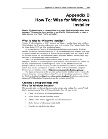
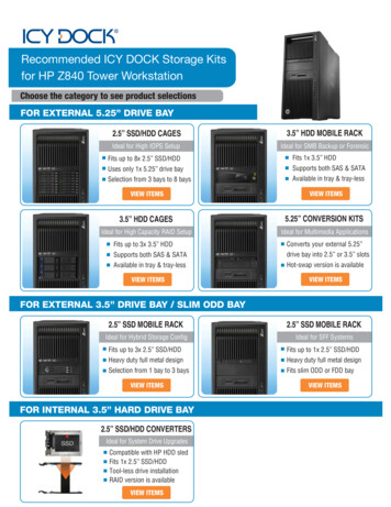
Figure 2. Upflow Outline DrawingInstaller’s Guide618-CD26D1-13
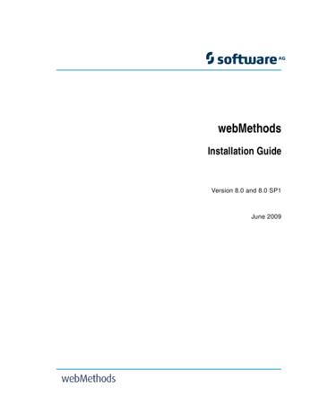
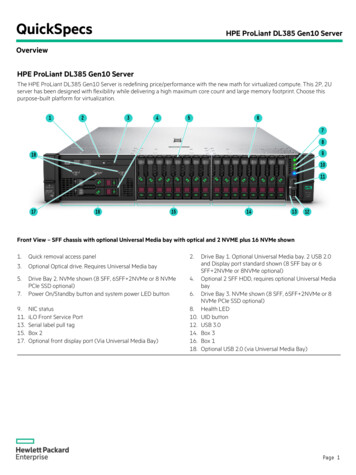
Figure 3. Downflow Outline DrawingInstaller’s Guide18-CD26D1-137
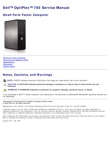
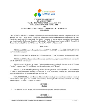
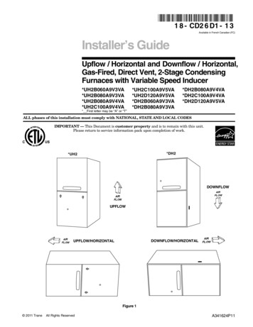
Installer’s GuideTable 1 Required floor opening: (DOWNFLOW)INSTALLATION INSTRUCTIONS! WARNING FIRE HAZARD. DO NOT INSTALL THE FURNACE DIRECTLYON CARPETING, TILE OR OTHER COMBUSTIBLE MATERIAL OTHER THAN WOOD FLOORING. FOR VERTICALDOWNFLOW APPLICATION, SUBBASE (BAYBASE205)MUST BE USED BETWEEN THE FURNACE AND COMBUSTIBLE FLOORING. WHEN THE DOWNFLOW FURNACE ISINSTALLED VERTICALLY WITH A CASED COIL, A SUBBASE IS NOT REQUIRED.The bottom panel of the upflow furnace must be removed forbottom return air.Remove the filter and lay the furnace on its back. Remove thetwo 5/16" hex screws securing the bottom front channel to thecabinet. Lower the front edge of the bottom front channel andpull forward to remove the channel. The bottom return airpanel will now easily slide out of the cabinet. Reinstall thebottom front channel and filter for upflow bottom returninstallations.UPFLOW INSTALLATIONStandoffs and screws (See Figure 4) are included with thecased coils for attachment to the Furnace. There are clearance alignment holes near the bottom of the coil wrapper.Drill screws are used to engage the Furnace top flanges. Thestandoff is inserted into the cabinet alignment hole. The drillscrews are inserted through the standoffs then screwed intothe Furnace flange. The coil is always placed downstream ofthe Furnace airflow. The above instructions apply only if thecoil is on top of an upflow FurnaceFOR VERTICALCASECO DILDRILL SCREWS (4)STANDOFFS 012345678901234567890121234567890123456A 6B igure 6HORIZONTAL INSTALLATIONThe coil and Furnace must be fully supported when used inthe horizontal position. It is always recommended that anauxiliary drain pan be installed under a horizontally installed evaporator coil or 90% Gas Furnace. Connect theauxiliary drain line to a separate drain line (no trap is neededin this line).Three brackets (with screws) are included with downflowfurnaces for installtion to stabilize and secure the 2/4TXCcased coil in the horizontal position. See Figure 8.The cased coil is secured to the Furnace. The brackets mountusing the rear screws on the coil case. Use the screws providedto secure the bracket to the Furnace. The remaining bracketis placed as close to horizontal center as possible between thecoil and the Furnace, converted to horizontal, aligns andattaches to the TXC coil.The Furnace and the cased coil must be properly supported.The Furnace may be installed in an attic or crawl space in thehorizontal position by placing the Furnace on the left side (asviewed from the front in the vertical position). The horizontalFurnace installation in an attic should be on a serviceplatform large enough to allow for proper clearances on allsides and service access to the front of the Furnace (SeeFigure 6 & Table 1). Line contact is only permissible betweenlines formed by intersections of the top and two sides of thefurnace casing and building joists, studs, or framing.The Furnace may be placed horizontally in a crawl space on apad or other noncombustible material which will raise theunit for sufficient protection from moisture.SCREWSUPFU FLORN WACEFLOOR OPENING PLENUM OPENINGCABINETRETURNWIDTH DUCT WIDTH"A""B""C""D"17-1/2"16-1/4"16-5/8" 20-1/8"15-5/8"19-3/8"21"19-3/4"20-1/8" 20-1/8"19-1/8"19-3/8"24-1/2"23-1/4"23-5/8" 20-1/8"22-5/8"19-3/8"(BOTH SIDES)STANDOFFS(BOTH SIDES)Figure 4DOWNFLOW INSTALLATIONThe Furnace must be supported at both ends and themiddle when installed horizontally. The Furnace mustalso be elevated approximately 4-6 inches to allowclearance for the condensate drain to exit the cabinet inthe horizontal position.Figure 5Table 2MINIMUM CLEARANCE FROM COMBUSTIBLE MATERIALS FORUPFLOW/HORIZONTAL AND DOWNFLOW/ HORIZONTAL FURNACESUNIT T0"NOTE: CLEARANCE REQUIRED AT TOP OF PLENUM IS 1"FURNACE SURFACE8HORIZONTALCLOSET1"3"1"3"0"HORIZONTALALCOVE / ATTIC0"6"1"18"0"IMPORTANT:The 2/4TXC cased coil mustbe placed downstream of thefurnace. In horizontal installations, the apex of the coilmay point either toward oraway from the furnace. Seethe 2/4TXC coil Installer'sGuide for more details.18-CD26D1-13
Installer’s GuideThe horizontal Furnace may also be suspended from thejoists using all-thread rods with a substantial metal supportframe that supports the entire length of the furnace. Therods need to be of sufficient length to allow for proper clearances from combustible materials. The frame needs to be atleast 32" in length to allow for access to service panels.If the Furnace is suspended using steel strap, it must besupported at all four corners and in the middle at the front ofthe Furnace.UPFLOW/HORIZONTALSHOWN WITHDIRECT VENTFigure 7CASED COIL CONNECTIONBRACKET FOR DOWNFLOWFURNACE IN HORIZONTALDOWNFLOW ONLYFigure 8AIR FOR COMBUSTION AND VENTILATIONThe following warning complies with State of California law, Proposition 65.! WARNING HAZARDOUS GASES!EXPOSURE TO FUEL SUBSTANCES OR BY-PRODUCTSOF INCOMPLETE FUEL COMBUSTION IS BELIEVED BYTHE STATE OF CALIFORNIA TO CAUSE CANCER,BIRTH DEFECTS, OR OTHER REPRODUCTIVE HARM.Adequate flow of combustion and ventilating air must not beobstructed from reaching the Furnace. Air openings providedin the Furnace casing must be kept free of obstructions whichrestrict the flow of air. Airflow restrictions affect the efficiencyand safe operation of the Furnace. Keep this in mind shouldyou choose to remodel or change the area which contains yourFurnace. Furnaces must have a free flow of air for properperformance.Provisions for combustion and ventilation air shall be madein accordance with “latest edition” of Section 5.3, Air forCombustion and Ventilation, of the National Fuel Gas Code,ANSI Z223.1, or Sections 7.2, 7.3 or 7.4 of CSA B149.1Installation Codes, and applicable provisions of the localbuilding codes. Special conditions created by mechanicalexhausting of air and fireplaces must be considered to avoidunsatisfactory Furnace operation.UNCONFINED50 CU. FT. OR MOREPER 1000 BTU/ HR. INPUTALL EQUIP. INSTALLEDFigure 9Furnace locations may be in a confined space (see Figure 10)or an unconfined space (See Figure 9).18-CD26D1-13Table 3MINIMUM AREA IN SQUARE FEETFOR UNCONFINED SPACE INSTALLATIONSWITH 8 FT. CEILINGFURNACEMAXIMUM BTUH MINIMUM AREA IN SQUAREINPUT RATING FEET OF UNCONFINED 875Unconfined space is defined in Table 3 and Figure 9. Thesespaces may have adequate air by infiltration to provide airfor combustion, ventilation, and dilution of flue gases.Buildings with tight construction (for example, weatherstripping, heavily insulated, caulked, vapor barrier, etc.), mayneed additional air provided as described for confined space.1.All air from inside the building as in Figure 11: The confined space shall be provided with two permanentopenings communicating directly with an additionalroom(s) of sufficient volume so that the combined volumeof all spaces meets the criteria for an unconfined space.The total input of all gas utilization equipment installedin the combined space shall be considered in making thisdetermination. Refer to Table 4, for minimum openareas required.2. All air from outdoors as in Figure 12: The confined spaceshall be provided with two permanent openings, onecommencing within 12 inches of the top and one commencing within 12 inches of the bottom of the enclosure.The openings shall communicate directly, or by ducts,with the outdoors or spaces (crawl or attic) that freelycommunicate with the outdoors. Refer to Table 4, forminimum open areas required.CONFINEDLESS THAN 50 CU. FT.PER 1000 BTU/HR. INPUTALL EQUIP INSTALLEDFigure 10Table 4MINIMUM FREE AREA IN SQUARE INCHESEACH OPENING (FURNACE ,00080,000100,000120,000140,000100100100120140Air From 070Confined spaces are installations with less than 50 cu. ft. ofspace per 1000 BTU/ hr input from all equipment installed.Confined space is defined in Figure 10. Air for combustionand ventilation requirements can be supplied from inside thebuilding as in Figure 11 or from the outdoors, as in Figure 12.3. The following types of installations will require use ofOUTDOOR AIR for combustion, due to chemicalexposures:* Commercial buildings* Buildings with indoor pools* Furnaces installed in commercial laundry rooms* Furnaces installed in hobby or craft rooms9
Installer’s Guide* Furnaces installed near chemical storage areas.Exposure to the following substances in the combustion air supply will also require OUTDOOR AIR forcombustion:* Permanent wave solutions* Chlorinated waxes and cleaners* Chlorine based swimming pool chemicals* Water softening chemicals* Deicing salts or chemicals* Carbon Tetrachloride* Halogen type refrigerants* Cleaning solvents (such as perchloroethylene)* Printing inks, paint removers, varnish, etc.* Hydrochloric acid* Cements and glues* Antistatic fabric softeners for clothes dryers* Masonry acid washing materialsFigure 11NOTE: Extended warranties are not available in someinstances. Extended warranty does not cover repairs toequipment installed in establishments with corrosiveatmospheres, including but limited to, dry cleaners, beautyshops, and printing facilities.DUCT CONNECTIONS! CAUTION SAFETY HAZARDSharp Edge Hazard. Be careful of sharp edges on equipment or any cuts made on sheet metal while installing orservicing. Personal injury may result.Air duct systems should be installed in accordance withstandards for air conditioning systems, National FireProtection Association Pamphlet No. 90. They should besized in accordance with ACCA Manual D.Central Furnaces, when used in connection with cooling units,shall be installed in parallel or on the upstream side of thecooling coil to avoid condensation in the heat exchanger. With aparallel flow arrangement, the dampers or other means used tocontrol flow of air shall be adequate to prevent chilled air fromentering the Furnace, and if manually operated, must beequipped with means to prevent operation of either unit unlessthe damper is in full heat or cool position.Flexible connections of nonflammable material may be used forreturn air and discharge connections to reduce the transmissionof vibration. Though these units have been specifically designedfor quiet, vibration free operation, air ducts can act as soundingboards and could, if poorly installed, result in vibration to theannoyance level.When the Furnace is located in a utility room adjacent to theliving area, the system should be carefully designed withreturns to minimize noise transmission through the returnair grille. Although these Furnaces are designed with largeblowers operating at moderate speeds, any blower moving ahigh volume of air will produce audible noise which could beobjectionable when the unit is located very close to a livingarea. It is often advisable to route the return air ducts underthe floor or through the attic. Such design permits theinstallation of air return remote from the living area (i.e.central hall).When the Furnace is installed so that the supply ducts carryair circulated by the Furnace to areas outside the spacecontaining the Furnace, the return air shall also be handledby a duct(s) sealed to the Furnace and terminating outsidethe space containing the Furnace.10Figure 1218-CD26D1-13
Installer’s GuideWhere there is no complete return duct system, thereturn connection must be run full size from the Furnace to a location outside the utility room, basement,attic, or crawl space.Do Not install return air through the back of the Furnacecabinet.Carbon monoxide, fire or smoke can cause serious bodilyinjury, death, and/or property damage.A variety of potential sources of carbon monoxide can be foundin a building or dwelling such as gas-fired clothes dryers, gascooking stoves, water heaters, furnaces and fireplaces. TheU.S. Consumer Product Safety Commission recommendsthat users of gas-burning appliances install carbon monoxidedetectors as well as fire and smoke detectors per the manufactures installation instructions to help alert dwellingoccupants of the presence of fire, smoke or unsafe levels ofcarbon monoxide. These devices should be listed by Underwriters Laboratories, Inc. Standards for Single and MultipleStation Carbon Monoxide Alarms, UL 2034 or CSA International Standard, Residential Carbon Monoxide AlarmingDevices, CSA 6.19.NOTE: The manufacturer of your Furnace DOES NOT testany detectors and makes no representations regarding anybrand or type of detector.All return air duct systems should provide for installation ofreturn air filters.PREPARATION FOR UPFLOW BOTTOM AND SIDE RETURNAIR FILTER INSTALLATIONAll return air duct systems should provide for installation ofreturn air filters.1. Determine the appropriate position to set the furnace inorder to existing supply and return ductwork.2. The return air filter is shipped in either the bottom orside location. Remove the filter by first turning the twolatches on the blower door and tilting the door forward toremove. Remove the filter by sliding it out.3. For upflow side return installations, remove the insulationaround the opening in the blower compartment.4. The side panels of the upflow furnace include locatingnotches that are used as guides for cutting an opening forreturn air, refer to Figure 13 and the outline drawing onpage 6 for duct connection dimensions for variousfurnaces.5. If a 3/4" flange is to be used for attaching the air inletduct, add to cut where indicated by dotted lines inFigure 13. Cut corners diagonally and bend outward toform flange.6. If flanges are not required, and a filter frame is installed,cut between locating notches (See Figure 13).7. The bottom panel of the upflow
7. When a Furnace is installed so that supply ducts carry air circulated by the Furnace to areas outside the space containing the Furnace, the return air shall also be handled by a duct(s) sealed to the Furnace casing and terminating outside the space containing the Furnace. 8. A gas-fired Furnace for installation in a residential