Transcription
PG8M/PG8JInstallation, Start-up, Operating, andService and Maintenance Instructions-Series CThe Payne PG8M/PG8J 80% AFUE Gas Furnaces feature 4way multipoise design and through-the-furnace downflowventing. The PG8M/PG8J furnaces are approved for use withnatural or propane gas and the PG8J is also approved for use inLow Nox Air Quality Management Districts.STANDARD FEATURES Four-position furnace: upflow, horizontal right, horizontalleft, downflowElectronic control centerAdjustable heating air temperature riseLED diagnostics and self test featureHot surface ignition (HSI)Twinning in Upflow, Downflow and HorizontalLIMITED WARRANTY 20-year warranty on “Super S ” heat exchanger 5-year parts warranty on all other componentsCatalog No: 53PG-8J5Form No. IM-PG8J-055-05
Single-StageInduced-Combustion4-Way Multipoise FurnaceCancels: II tion, Start-up, Operating, andService and Maintenance InstructionsSeries 120/CNOTE: Read the entire instruction manual before starting theinstallation.This symbol indicates a change since the last issue. Portions of the text and tables are reprinted from NFPA 54/ANSI Z223.1-2002 ,with permission of National Fire Protection Association, Quincy, MA 02269 andAmerican Gas Association, Washington DC 20001. This reprinted material is not thecomplete and official position of the NFPA or ANSI on the referenced subject, whichis represented only by the standard in its entirety.TABLE OF CONTENTSSAFETY CONSIDERATIONS .2INTRODUCTION .4CODES AND STANDARDS.4Safety.5General Installation.5Combustion and Ventilation Air .5Duct Systems .5Acoustical Lining and Fibrous Glass Duct.5Gas Piping and Gas Pipe Pressure Testing.5Electrical Connections .5ELECTROSTATIC DISCHARGE (ESD) PRECAUTIONSPROCEDURE .5LOCATION.5General .5Location Relative to Cooling Equipment .7AIR FOR COMBUSTION AND VENTILATION .7INSTALLATION .10Upflow Installation .10Bottom Return Air Inlet .10Side Return Air Inlet.10Leveling Legs (If Desired).10Downflow Installation .10Bottom Return Air Inlet .11Horizontal Installation .11Suspended Furnace Support .11Platform Furnace Support .11Roll-Out Protection.11Bottom Return Air Inlet .11Side Return Air Inlet.11Filter Arrangement.11Air Ducts.11General Requirements .11Ductwork Acoustical Treatment .12Supply Air Connections .12Return Air Connections.14Gas Piping.15Electrical Connections .19115-V Wiring.19J-Box Relocation .20Electrical Connection to J-Box .21Power Cord Installation in Furnace J-Box .21BX Cable Installation in Furnace J-Box .2224-V Wiring.22Accessories .22Venting .22General Venting Requirements .23Masonry Chimney Requirements.23Appliance Application Requirements .24Additional Venting Requirements.26Sidewall Venting .26START-UP, ADJUSTMENT, AND SAFETY CHECK .27General .27Start-Up Procedures .27Adjustments.31Check Safety Controls .34Checklist.35SERVICE AND MAINTENANCE PROCEDURES.35Introduction .35General.35Electrical Controls and Wiring .36Care and Maintenance .37Cleaning and/or Replacing Air Filter .37Blower Motor and Wheel.37Cleaning Heat Exchanger.40Sequence of Operation.44Wiring Diagrams.45Troubleshooting .45Manufacturer reserves the right to discontinue, or change at any time, specifications or designs without notice and without incurring obligations.Book 1 4PC 101Catalog No. See CoverPrinted in U.S.A.Form 58ST-13SIPg 15-05Replaces: 58ST-12SITab 6a 8a
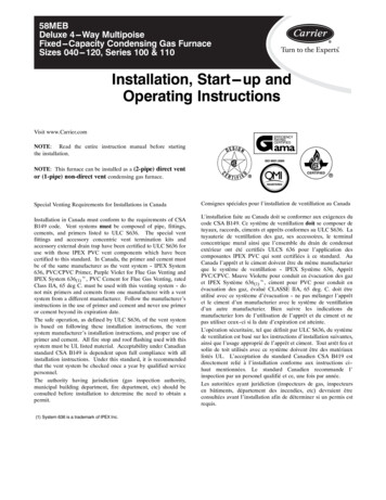
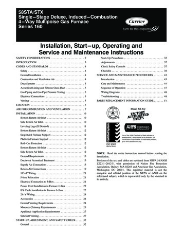
28-7/8"26-1/8"(FLUE COLLAR)25-1/4"2-7/16"A22-9/16"JUNCTION -13/16"8-9/16"7/8" DIAACCESSORYAIRFLOW1/2" DIA THERMOSTATWIRE ENTRYOUTLET1/2" DIA. K.O.THERMOSTATWIRE ENTRY1-3/4" DIA.RIGHT HANDGAS ENTRY11/16"7-3/4"9-5/8"11-1/2"3-15/16"LEFT HAND GASENTRY7/8" DIA. K.O. WIRE ENTRY33-5/16"ALTERNATEJUNCTION BOXLOCATIONS (TYP)24-7/8"VENT OUTLET5 PLACES (TYP)7/8" DIA. ACCESSORY14-7/8"7/8" DIA. ACCESSORY5-1/2"5-1/2"11/16"21-5/8"BOTTOM INLET1-11/16"E11/16"3-3/4"1-1/2"22-1/16"SIDE INLET24"CASING1-1/4"1"A04037NOTES:1. Two additional 7/8-in. diameter holes are located in the top plate.2. Minimum return-air openings ar furnace, based on metal duct. If flex duct is used, see flex duct manufacturer’s recommendations for equivalent diameters.a. For 800 CFM-16-in. round or 14 1/2 x 12-in. rectangle.b. For 1200 CFM-20-in. round or 14 1/2 x 19 1/2-in. rectangle.c. For 1600 CFM-22-in. round or 14 1/2 x 22-in. rectangle.d. For airflow requirements above 1800 CFM, see Air Delivery table in Product Data literature for specificuse of single side inlets. The use of both side inlets, a combination of 1 side and the bottom, or thebottom only will ensure adequate return air openings for airflow requirements above 1800 CFM. Fig. 1—Dimensional DrawingSAFETY CONSIDERATIONSThese instructions cover minimum requirements and conform toexisting national standards and safety codes. In some instances,these instructions exceed certain local codes and ordinances,especially those that may not have kept up with changing residential construction practices. We require these instructions as aminimum for a safe installation.FIRE, EXPLOSION, ELECTRICAL SHOCK, ANDCARBON MONOXIDE POISONING HAZARDFailure to follow this warning could result in dangerousoperation, serious injury, death, or property damage.Improper installation, adjustment, alteration, service, maintenance, or use can cause carbon monoxide poisoning, explosion, fire, electrical shock, or other conditions which maycause personal injury or property damage. Consult a qualifiedservice agency, local gas supplier, or your distributor orbranch for information or assistance. The qualified serviceagency must use only factory-authorized and listed kits oraccessories when modifying this product.CUT HAZARDFailure to follow this caution may result in personal injury.Sheet metal parts may have sharp edges or burrs. Use care andwear appropriate protective clothing, safety glasses andgloves when handling parts and servicing furnaces.Wear safety glasses and work gloves. Have fire extinguisheravailable during start-up and adjustment procedures and servicecalls. When you see this symbol onThis is the safety-alert symbolthe furnace and in instructions or manuals, be alert to the potentialfor personal injury.FURNACE RELIABILITY HAZARDImproper installation or misapplication of furnace may require excessive servicing or cause premature componentfailure.Application of this furnace should be indoors with specialattention given to vent sizing and material, gas input rate, airtemperature rise, unit leveling, and unit sizing.Understand the signal words DANGER, WARNING, and CAUTION. These words are used with the safety-alert symbol. DANGER identifies the most serious hazards which will result in severepersonal injury or death. WARNING signifies a hazard whichcould result in personal injury or death. CAUTION is used toidentify hazards which may result in minor personal injury orproduct and property damage. NOTE is used to highlight suggestions which will result in enhanced installation, reliability, oroperation.Installing and servicing heating equipment can be hazardous due togas and electrical components. Only trained and qualifiedpersonnel should install, repair, or service heating equipment.Untrained personnel can perform basic maintenance functionssuch as cleaning and replacing air filters. All other operations mustbe performed by trained service personnel. When working onheating equipment, observe precautions in literature, on tags, andon labels attached to or shipped with furnace and other safetyprecautions that may apply.1. Use only with type of gas approved for this furnace. Refer tothe furnace rating plate.2. Install this furnace only in a location and position as specifiedin the “Location” section of these instructions.2
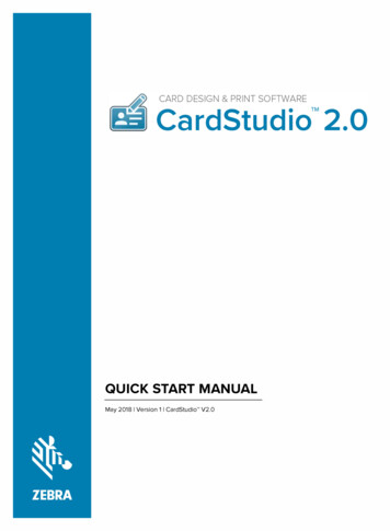
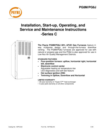
INSTALLATIONTOP / PLENUMDESSUS / CHAMBRED'AIRMINIMUM INCHES CLEARANCE TO COMBUSTIBLE CONSTRUCTIONDISTANCE MINIMALE EN POUCES AUX CONSTRUCTIONS COMBUSTIBLESThis forced air furnace is equipped for use with This furnace is approved for UPFLOW, DOWNFLOW, andHORIZONTAL installations.natural gas at altitudes 0-10,000 ft (0-3,050m).Cette fournaise est approuvée pour l 'installation HORIZONTALEAn accessory kit, supplied by theet la circulation d 'air VERS LE HAUT et VERS LE BAS.manufacturer, shall be used to convert to propanegas use or may be required for some natural gas1"Clearance arrowsapplications.Les fléches de dégagementne change pas avecThis furnace is for indoor installation in a do not change withl 'orientation de la fournaise.furnace orientation.building constructed on site.This furnace may be installed on combustibleflooring in alcove or closet at minimum clearance0"as indicated by the diagram from combusitble0"BEmaterial.AR ACID È *SKTRIThis furnace may be used with a Type B-1 VentEÈRCÔAC SEEand may be vented in common with other gasRN NA IUF URfired appliances.FONTOF R AN TAVFRA V ONTANTSEEN R VITRET C EIEN3"MINBOTTOMDESSOUS* 0"DESIÉÔTC0"Cette fournaise à air pulsé est équipéepour utilisation avec gaz naturel et altitudescomprises entre 0-3,050m (0-10,000 pi).Utiliser une trousse de conversion, fournie parle fabricant, pour passer au gaz propane ou pourcertaines installations au gaz naturel.Cette fournaise est prévue pour êtreinstallée dans un bâtiment construit sur place.Cette fournaise peut être installée surun plancher combustible dans une alcôve oudans un garde-robe en respectant le minimumd'espace libre des matériaux combustibles, telqu indiqué sur le diagramme.Cette fournaise peut être utilisée avec unconduit d évacuation de Type B-1 ou connectéeau conduit ommun d 'autres appareils à gaz.†24"MINØClearance in inchesDégagement (po).Vent Clearance to combustibles:For Single Wall vents 6 inches (6 po).For Type B-1 vent type 1 inch (1 po).Dégagement de l évent avec combustibles:Pour conduit d évacuation à paroi simple 6 po (6 inches).Pour conduit d évacuation de Type B-1 1 po (1 inch).MINIMUM INCHES CLEARANCE TO COMBUSTIBLE CONSTRUCTIONDOWNFLOW POSITIONS:† Installation on non-combusibible floors only.Ø*For Installation on combustible flooring only when installed on special base, Part No. KGASB0201ALL,Coil Assembly, Part No. CD5 or CK5, or Coil Casing, Part No. KCAKC.18 inches front clearance required for alcove.Indicates supply or return sides when furnace is in the horizontal position. Line contact only permissiblebetween lines formed by intersections of the Top and two Sides of the furnace jacket, and building joists,studs or framing.DÉGAGEMENT MINIMUM EN POUCES AVEC ÉLÉMENTSDE CONSTRUCTION COMBUSTIBLESPOUR LA POSITION COURANT DESCENDANT:† Pour l installation sur plancher non combustible seulement.Ø*Pour l installation sur un plancher combustible seulement quand on utilise la base spéciale, piècenº KGASB0201ALL, l ensemble serpentin, pièce nº CD5 ou CK5, ou le carter de serpentin, piècenº KCAKC.Dans une alcôve, on doit maintenir un dégagement à l avant de 18 po (450mm).La poistion indiquée concerne le côté d entrée ou de retour quand la fournaise est dans laposition horizontale.Le contact n est permis qu entre les lignes formées par les intersections du dessus et desdeux côtés de la cherrise de la fournaise et les solives, montant sous cadre de charpente.327590-101 REV. CA04123 Fig. 2—Clearances to Combustibles3
Table 1—Dimensions (IN.)FURNACESIZEACABINET 1/22323FC.L. TOP ANDBOTTOMFLUE -1/16FLUECOLLAR*(IN.)SHIP WT. 2149163170* 5” or 6” vent connector may be required in some cases.13. These furnaces SHALL NOT be installed directly on carpeting, tile, or any other combustible material other than woodflooring. In downflow installations, factory accessory floorbase MUST be used when installed on combustible materialsand wood flooring. Special base is not required when thisfurnace is installed on manufacturer’s Coil Assembly Part No.CD5 or CK5, or when Coil Box Part No. KCAKC is used. SeeFig. 2 for clearance to combustible construction information.3. Provide adequate combustion and ventilation air to the furnacespace as specified in “Air for Combustion and Ventilation”section.4. Combustion products must be discharged outdoors. Connectthis furnace to an approved vent system only, as specified inthe “Venting” section of these instructions.5. Never test for gas leaks with an open flame. Use a commercially available soap solution made specifically for the detection of leaks to check all connections, as specified in the “GasPiping” section.INTRODUCTIONSeries 120/C 4–way multipoise Category I fan-assistedfurnace is CSA design-certified. A Category I fan-assisted furnaceis an appliance equipped with an integral mechanical means toeither draw or force products of combustion through the combustion chamber and/or heat exchanger. The furnace is factoryshipped for use with natural gas. A CSA (A.G.A. and C.G.A.)listed gas conversion kit is required to convert furnace for use withpropane gas. This furnace is not approved for installation inmobile homes, recreational vehicles, or outdoors. This6. Always install furnace to operate within the furnace’s intendedtemperature-rise range with a duct system which has anexternal static pressure within the allowable range, as specified in the “Start-Up, Adjustments, and Safety Check” section.See furnace rating plate.7. When a furnace is installed so that supply ducts carry aircirculated by the furnace to areas outside the space containingthe furnace, the return air shall also be handled by duct(s)sealed to the furnace casing and terminating outside the spacecontaining the furnace. See “Air Ducts” section.This furnace is designed for minimum continuous return-airtemperature of 60 F db or intermittent operation down to 55 F dbsuch as when used with a night setback thermostat. Return-airtemperature must not exceed 85 F db. Failure to follow thesereturn-air temperature limits may affect reliability of heat exchangers, motors, and controls. (See Fig. 3.)8. A gas-fired furnace for installation in a residential garage mustbe installed as specified in the warning box in the “Location”section. 9. The furnace is not to be used for temporary heating ofbuildings or structures under construction. See page 7 cautionbox regarding the heating of buildings under construction.For accessory installation details, refer to the applicable instructionliterature.NOTE: Remove all shipping brackets and materials before operating the furnace.10. These Multipoise Gas-Fired Furnaces are CSA (formerlyA.G.A. and C.G.A.) design-certified for use with natural andpropane gases (see furnace rating plate) and for installation inalcoves, attics, basements, closets, utility rooms, crawlspaces,and garages. The furnace is factory-shipped for use withnatural gas. A CSA listed gas conversion kit is required toconvert furnace for use with propane gas.CODES AND STANDARDSFollow all national and local codes and standards in addition tothese instructions. The installation must comply with regulationsof the serving gas supplier, local building, heating, plumbing, andother codes. In absence of local codes, the installation mustcomply with the national codes listed below and all authoritieshaving jurisdiction.11. See Fig. 2 for required clearances to combustible construction.12. Maintain a 1-in. clearance from combustible materials tosupply air ductwork for a distance of 36 inches horizontallyfrom the furnace. See NFPA 90B or local code for furtherrequirements.4
Step 8—Venting US: NFGC; chapters 10 and 13 CANADA: NSCNGPIC Part 7 and Appendix CELECTROSTATIC DISCHARGE (ESD) PRECAUTIONSPROCEDURE FURNACE RELIABILITY HAZARDImproper installation or service of furnace may cause premature furnace component failure.Electrostatic discharge can affect electronic components.Take precautions during furnace installation and servicing toprotect the furnace electronic control. Precautions will prevent electrostatic discharges from personnel and hand toolswhich are held during the procedure. These precautions willhelp to avoid exposing the control to electrostatic dischargeby putting the furnace, the control, and the person at the sameelectrostatic potential.60A02055Fig. 3—Return Air TemperatureIn the United States and Canada, follow all codes and standards forthe following:1. Disconnect all power to the furnace. Multiple disconnects maybe required. DO NOT TOUCH THE CONTROL OR ANYWIRE CONNECTED TO THE CONTROL PRIOR TO DISCHARGING YOUR BODY’S ELECTROSTATIC CHARGETO GROUND.Step 1—Safety US: National Fuel Gas Code (NFGC) NFPA 54–2002/ANSIZ223.1–2002 and the Installation Standards, Warm Air Heatingand Air Conditioning Systems ANSI/NFPA 90B2. Firmly touch the clean, unpainted, metal surface of the furnacechassis which is close to the control. Tools held in a person’shand during grounding will be satisfactorily discharged.CANADA: CSA B149.1-00 National Standard of CanadaNatural Gas and Propane Installation Codes (NSCNGPIC)3. After touching the chassis, you may proceed to service thecontrol or connecting wires as long as you do nothing torecharge your body with static electricity (for example; DONOT move or shuffle your feet, do not touch ungroundedobjects, etc.).Step 2—General Installation US: Current edition of the NFGC and the NFPA 90B. Forcopies, contact the National Fire Protection Association Inc.,Batterymarch Park, Quincy, MA 02269 (www.NFPA.org); orfor only the NFGC, contact the American Gas Association, 400N. Capitol Street, N.W., Washington, DC 20001(www.AGA.org).4. If you touch ungrounded objects (and recharge your body withstatic electricity), firmly touch a clean, unpainted metalsurface of the furnace again before touching control or wires.CANADA: NSCNGPIC. For a copy, contact Standard Sales,CSA International, 178 Rexdale Boulevard, Etobicoke (Toronto), Ontario, M9W 1R3 Canada5. Use this procedure for installed and uninstalled (ungrounded)furnaces.Step 3—Combustion and Ventilation Air 6. Before removing a new control from its container, dischargeyour body’s electrostatic charge to ground to protect thecontrol from damage. If the control is to be installed in afurnace, follow items 1 through 4 before bringing the controlor yourself in contact with the furnace. Put all used and newcontrols into containers before touching ungrounded objects.US: Section 8.3 of the NFGC, Air for Combustion andVentilationCANADA: Part 7 of NSCNGPIC, Venting Systems and AirSupply for AppliancesStep 4—Duct Systems 7. An ESD service kit (available from commercial sources) mayalso be used to prevent ESD damage.US and CANADA: Air Conditioning Contractors Association(ACCA) Manual D, Sheet Metal and Air Conditioning Contractors National Association (SMACNA), or American Society of Heating, Refrigeration, and Air Conditioning Engineers(ASHRAE) 2001 Fundamentals Handbook Chapter 34 or 2000HVAC Systems and Equipment Handbook Chapters 9 and 16.LOCATIONGENERALSome assembly and modifications are required when used in anyof the four applications shown in Fig. 4.Step 5—Acoustical Lining and Fibrous Glass Duct US and CANADA: current edition of SMACNA and NFPA90B as tested by UL Standard 181 for Class I Rigid Air DuctsThis furnace must: Step 6—Gas Piping and Gas Pipe Pressure Testing US: NFGC; chapters 5, 6, 7, and 12 and National PlumbingCodes CANADA: NSCNGPIC Parts 3, 4, and 5, and Appendices A,B, E and H. not be installed directly on any combustible material other thanwood flooring (refer to SAFETY CONSIDERATIONS).Step 7—Electrical Connections US: National Electrical Code (NEC) ANSI/NFPA 70–2002 CANADA: Canadian Electrical Code CSA C22.1be installed so the electrical components are protected fromwater.5 be located close to the chimney or vent and attached to an airdistribution system. Refer to Air Ducts section. be provided ample space for servicing and cleaning. Alwayscomply with minimum fire protection clearances shown on thefurnace clearance to combustible construction label.
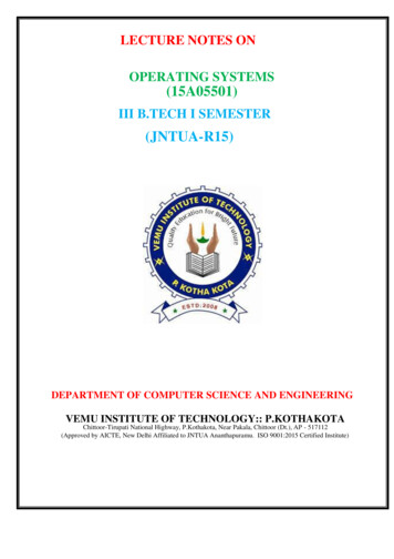
THE BLOWER ISLOCATED BELOW THEBURNER SECTION, ANDCONDITIONED AIR ISDISCHARGED UPWARD.THE BLOWER IS LOCATEDTO THE RIGHT OF THEBURNER SECTION, ANDAIR CONDITIONED AIR ISDISCHARGED TO THE LEFT.THE BLOWER ISLOCATED TO THE LEFTOF THE BURNER SECTION,AND CONDITIONED AIR ISDISCHARGED TO THE RIGHT.THE BLOWER ISLOCATED ABOVE THEBURNER SECTION, ANDCONDITIONED AIR ISDISCHARGED DOWNWARDA02097Fig. 4—Multipoise Orientations All fuel-burning equipment must be supplied with air for fuelcombustion. Sufficient air must be provided to avoid negativepressure in the equipment room or space. A positive seal must bemade between the furnace cabinet and the return-air duct toprevent pulling air from the burner area and from draft safeguardopening.CARBON MONOXIDE POISONING HAZARDFailure to follow this warning could result in personal injuryor death, and unit component damage.Corrosive or contaminated air may cause failure of partscontaining flue gas, which could leak into the living space.Air for combustion must not be contaminated by halogencompounds, which include fluoride, chloride, bromide, andiodide. These elements can corrode heat exchangers andshorten furnace life. Air contaminants are found in aerosolsprays, detergents, bleaches, cleaning solvents, salts, airfresheners, and other household products. Do not installfurnace in a corrosive or contaminated atmosphere. Makesure all combustion and circulating air requirements are met,in addition to all local codes and ordinances. Thefollowing types of furnace installations may require OUTDOOR AIR for combustion due to chemical exposures: Commercial buildings Buildings with indoor pools Laundry rooms Hobby or craft rooms, and Chemical storage areas18-IN. MINIMUMTO BURNERS If air is exposed to the following substances, it should not be usedA93044for combustion air, and outdoor air may be required for combustion: Permanent wave solutions Chlorinated waxes and cleaners Chlorine based swimming pool chemicals Water softening chemicals De-icing salts or chemicals Carbon tetrachloride Halogen type refrigerants Cleaning solvents (such as perchloroethylene) Printing inks, paint removers, varnishes, etc. Hydrochloric acid Cements and glues Antistatic fabric softeners for clothes dryers Masonry acid washing materialsFig. 5—Installation in a GarageFIRE, INJURY OR DEATH HAZARDImproper location or inadequate protection could result in fireor explosion.When the furnace is installed in a residential garage, theburners and ignition sources must be located at least 18 inchesabove the floor. The furnace must be located or protected toavoid damage by vehicles. When the furnace is installed in apublic garage, airplane hangar, or other building having ahazardous atmosphere, the furnace must be installed inaccordance with the NFGC or NSCNGPIC. (See Fig. 5.)6
PERSONAL INJURY AND/OR PROPERTY DAMAGEHAZARDImproper use or installation of this furnace may causepremature furnace component failure.This gas furnace may be used for heating buildings underconstruction provided that:-The furnace is permanently installed with all electricalwiring, piping, venting and ducting installed according tothese installation instructions. A return air duct is provided,sealed to the furnace casing, and terminated outside the spacecontaining the furnace. This prevents a negative pressurecondition as created by the circulating air blower, causing aflame rollout and/or drawing combustion products into thestructure.-The furnace is controlled by a thermostat. It may not be ″hotwired″ to provide heat continuously to the structure withoutthermostatic control.-Clean outside air is provided for combustion. This is tominimize the corrosive effects of adhesives, sealers and otherconstruction materials. It also prevents the entrainment ofdrywall dust into combustion air, which can cause foulingand plugging of furnace components.-The temperature of the return air to the furnace is maintained between 55 F (13 C) and 80 F (27 C), with noevening setback or shutdown. The use of the furnace whilethe structure is under construction is deemed to be intermittent operation per our installation instructions.-The air temperature rise is within the rated rise range on thefurnace rating plate, and the firing rate has been set to thenameplate value.-The filters used to clean the circulating air during theconstruction process must be either changed or thoroughlycleaned prior to occupancy.-The furnace, ductwork and filters are cleaned as necessaryto remove drywall dust and construction debris from allHVAC system components after construction is completed.-Verify proper furnace operating conditions including ignition, gas input rate, air temperature rise, and ventingaccording to these installation instructions.A02054Fig. 6—Prohibit Installation on BackAIR FOR COMBUSTION AND VENTILATIONProvisions for adequate combustion, ventilation, and dilution airmust be provided in accordance with: U.S. installations: Section 8.3 of the NFGC, Air for Combustion and Ventilation, and applicable provisions of the localbuilding codes. Canadian installations: Part 7 of the NSCNGPIC, VentingSystems and Air Supply for Appliances, and all authoritieshaving jurisdiction. FURNACE CORROSION HAZARDFailure to follow this caution may result in furnace damage.Air for combustion must not be contaminated by halogencompounds, which include fluoride, chloride, bromide, andiodide. These elements can corrode heat exchangers andshorten furnace life. Air contaminants are found in aerosolsprays, detergents, bleaches, cleaning solvents, salts, airfresheners, and other household products. FIRE, INJURY OR DEATH HAZARDFailure to follow this warning could result in unsafe furnaceoperation.DO NOT install the furnace on its back or hang furnace withcontrol compartment facing downward. Safety control operation will be adversely affected. Never connect return-air ductsto back of
1. Use only with type of gas approved for this furnace. Refer to the furnace rating plate. 2. Install this furnace only in a location and position as specified in the "Location" section of these instructions. NOTES: 1. Two additional 7/8-in. diameter holes are located in the top plate. 2. Minimum return-air openings ar furnace, based on .