Transcription
INSTALLATION MANUALHIGH EFFICIENCYTUBULAR HEAT EXCHANGER SERIESEFFICIENCYRATINGCERTIFIEDMODELS: DGAD / DGAE / DGAF(Single-Stage Downflow, 92% AFUE,Manufactured Housing or Modular Home Applications)60 - 100 MBH INPUT(17.6 - 29.3 KW) INPUTISO 9001Certified QualityManagement SystemLIST OF SECTIONSSAFETY . . . . . . . . . . . . . . . . . . . . . . . . . . . . . . . . . . . . . . . . . . . . . . . . 1DUCTWORK . . . . . . . . . . . . . . . . . . . . . . . . . . . . . . . . . . . . . . . . . . . . 4FILTERS . . . . . . . . . . . . . . . . . . . . . . . . . . . . . . . . . . . . . . . . . . . . . . . 7GAS PIPING . . . . . . . . . . . . . . . . . . . . . . . . . . . . . . . . . . . . . . . . . . . . 8ELECTRICAL POWER . . . . . . . . . . . . . . . . . . . . . . . . . . . . . . . . . . . 10COMBUSTION AIR AND VENT SYSTEM . . . . . . . . . . . . . . . . . . . . .11CONDENSATE PIPING . . . . . . . . . . . . . . . . . . . . . . . . . . . . . . . . . . .18SAFETY CONTROLS . . . . . . . . . . . . . . . . . . . . . . . . . . . . . . . . . . . .20START-UP AND ADJUSTMENTS . . . . . . . . . . . . . . . . . . . . . . . . . . .20WIRING DIAGRAM . . . . . . . . . . . . . . . . . . . . . . . . . . . . . . . . . . . . . .28LIST OF FIGURESCombustible Floor Base Accessory . . . . . . . . . . . . . . . . . . . . . . . . . . . 5Transition Kit Assembly . . . . . . . . . . . . . . . . . . . . . . . . . . . . . . . . . . . . 6Attachment to Structure . . . . . . . . . . . . . . . . . . . . . . . . . . . . . . . . . . . . 6Blend Air Bracket . . . . . . . . . . . . . . . . . . . . . . . . . . . . . . . . . . . . . . . . . 6Dimensions . . . . . . . . . . . . . . . . . . . . . . . . . . . . . . . . . . . . . . . . . . . . . 7Mobile Home Filter Frame Accessories . . . . . . . . . . . . . . . . . . . . . . . . 7Modular Home Return Filter Grill and Return Duct Installation . . . . . . 8Convertible Gas Valve . . . . . . . . . . . . . . . . . . . . . . . . . . . . . . . . . . . . . 8Downflow Gas Piping . . . . . . . . . . . . . . . . . . . . . . . . . . . . . . . . . . . . . . 8Electrical Wiring . . . . . . . . . . . . . . . . . . . . . . . . . . . . . . . . . . . . . . . . . 10Line Wiring Connections . . . . . . . . . . . . . . . . . . . . . . . . . . . . . . . . . . 11Single Stage Heat Thermostat Connections . . . . . . . . . . . . . . . . . . . 11Accessory Connections . . . . . . . . . . . . . . . . . . . . . . . . . . . . . . . . . . . 11Dimensions . . . . . . . . . . . . . . . . . . . . . . . . . . . . . . . . . . . . . . . . . . . . 12Home Layout . . . . . . . . . . . . . . . . . . . . . . . . . . . . . . . . . . . . . . . . . . . 14Downflow Vent Assembly . . . . . . . . . . . . . . . . . . . . . . . . . . . . . . . . . . 15Termination Configuration - 1 Pipe (Modular Installations Only) . . . .15Termination Configuration - 2 Pipe . . . . . . . . . . . . . . . . . . . . . . . . . . .15Double Horizontal Sealed Combustion Air and Vent Termination . . .16Double Vertical Sealed Combustion Air and Vent Termination . . . . .16Sealed Combustion Air Intake Connection and Vent Connection . . .16Combustion Airflow Path Through The Furnace Casingto the Burner Box (Modular Home Installations Only) . . . . . . . . . . . .17Outside and Ambient Combustion Air(Modular Home Installations Only) . . . . . . . . . . . . . . . . . . . . . . . . . . .17Attic Combustion Air Termination . . . . . . . . . . . . . . . . . . . . . . . . . . . .18Condensate Drain Internal Hose Routing . . . . . . . . . . . . . . . . . . . . . .18Downflow Condensate Drain Hose Configuration . . . . . . . . . . . . . . .19Pressure Switch Tubing Routing . . . . . . . . . . . . . . . . . . . . . . . . . . . .20Gas Valve . . . . . . . . . . . . . . . . . . . . . . . . . . . . . . . . . . . . . . . . . . . . . .23Reading Gas Pressure . . . . . . . . . . . . . . . . . . . . . . . . . . . . . . . . . . . .24Furnace Control Board . . . . . . . . . . . . . . . . . . . . . . . . . . . . . . . . . . . .24Wiring Diagram . . . . . . . . . . . . . . . . . . . . . . . . . . . . . . . . . . . . . . . . . .28LIST OF TABLESUnit Clearances to Combustibles . . . . . . . . . . . . . . . . . . . . . . . . . . . . . 4Nominal Manifold Pressure . . . . . . . . . . . . . . . . . . . . . . . . . . . . . . . . . 9Electrical and Performance Data . . . . . . . . . . . . . . . . . . . . . . . . . . . . 10Maximum Equivalent Pipe Length . . . . . . . . . . . . . . . . . . . . . . . . . . . 12Equivalent Length of Fittings . . . . . . . . . . . . . . . . . . . . . . . . . . . . . . . 12Elbow Dimensions . . . . . . . . . . . . . . . . . . . . . . . . . . . . . . . . . . . . . . . 12Combustion Air Intake and Vent Connection Size at Furnace(All Models) . . . . . . . . . . . . . . . . . . . . . . . . . . . . . . . . . . . . . . . . . . . . 12Estimated Free Area . . . . . . . . . . . . . . . . . . . . . . . . . . . . . . . . . . . . . .17Free Area - Outdoor Air . . . . . . . . . . . . . . . . . . . . . . . . . . . . . . . . . . .17Unconfined Space Minimum Area in Square Inch . . . . . . . . . . . . . . .17Condensate Drain Hose . . . . . . . . . . . . . . . . . . . . . . . . . . . . . . . . . . .19Inlet Gas Pressure Range . . . . . . . . . . . . . . . . . . . . . . . . . . . . . . . . .23Nominal Manifold Pressure . . . . . . . . . . . . . . . . . . . . . . . . . . . . . . . . .23Blower Performance CFM . . . . . . . . . . . . . . . . . . . . . . . . . . . . . . . . .26Filter Performance - Pressure Drop Inches W.C. and (kPa) . . . . . . . .26Field Installed Accessories - Non-Electrical . . . . . . . . . . . . . . . . . . . .27SECTION I: SAFETYThis is a safety alert symbol. When you see this symbol onlabels or in manuals, be alert to the potential for personalinjury.Understand and pay particular attention to the signal words DANGER,WARNING, or CAUTION.DANGER indicates an imminently hazardous situation, which, if notavoided, will result in death or serious injury.Improper installation may create a condition where the operation ofthe product could cause personal injury or property damage.Improper installation, adjustment, alteration, service or maintenance can cause injury or property damage. Refer to this manualfor assistance or for additional information, consult a qualified contractor, installer or service agency.WARNING indicates a potentially hazardous situation, which, if notavoided, could result in death or serious injury.CAUTION indicates a potentially hazardous situation, which, if notavoided may result in minor or moderate injury. It is also used toalert against unsafe practices and hazards involving only property damage.This product must be installed in strict compliance with the installation instructions and any applicable local, state, and national codesincluding, but not limited to building, electrical, and mechanicalcodes.268882-UIM-A-0407
268882-UIM-A-0407SPECIFIC SAFETY RULES AND PRECAUTIONS1.Only Natural gas or Propane (LP) gas are approved for use withthis furnace. Refer to the furnace rating plate or SECTION IV ofthese instructions.Install this furnace only in a location and position as specified inSECTION I of these instructions.A gas-fired furnace for installation in a residential garage must beinstalled as specified in SECTION I of these instructions.Provide adequate combustion and ventilation air to the furnacespace as specified in SECTION VI of these instructions.Combustion products must be discharged outdoors. Connect thisfurnace to an approved vent system only, as specified in SECTION VI of these instructions.2.3.4.5.FIRE OR EXPLOSION HAZARDFailure to follow the safety warnings exactly could result in seriousinjury, death or property damage.Never test for gas leaks with an open flame. Use a commerciallyavailable soap solution made specifically for detection of leaks tocheck all connections. A fire or explosion may result causing property damage, personal injury or loss of life.6.7.8.9.10.11.12.13.2Tests for gas leaks as specified in SECTION IX of these instructions.Always install the furnace to operate within the furnace’s intendedtemperature rise range. Only connect the furnace to a duct systemwhich has an external static pressure within the allowable range,as specified on the furnace rating plate.When a furnace is installed so that supply ducts carry air circulatedby the furnace to areas outside the space containing the furnace,the return air may also be handled by duct(s) sealed to the furnacecasing and terminating outside the space containing the furnace.The return air duct system is not required by the furnace manufacturer provided the combustion air and vent system have beeninstalled and maintained as a Two Pipe Sealed Combustion AirSystem and provided a return air duct system and return air plenum are not required by state, local, or regional codes.It is permitted to use the furnace for heating of buildings or structures under construction. Installation must comply with all manufacturer’s installation instructions including: Proper vent installation; Furnace operating under thermostatic control; Return air duct sealed to the furnace; Air filters in place; Set furnace input rate and temperature rise per rating platemarking; Means for providing outdoor air required for combustion; Return air temperature maintained between 55ºF (13ºC) and80ºF (27ºC); The air filter must be replaced upon substantial completion ofthe construction process; Clean furnace, duct work and components upon substantialcompletion of the construction process, and verify furnaceoperating conditions including ignition, input rate, temperaturerise and venting, according to the manufacturer’s instructions.When installed in a Manufactured (Mobile) Home, combustion airshall not be supplied from occupied spaces.The size of the unit should be based on an acceptable heat losscalculation for the structure. ACCA, Manual J or other approvedmethods may be used.Manufactured (Mobile) Home Installation: This appliance mustbe installed in a two-pipe (sealed combustion) configuration. Thecombustion air pipe must terminate in the same atmospheric zone,external to the building.Modular Home Installations:This appliance may be installed in the following configurations:A. A (two pipe) Sealed Combustion Configuration. This configuration has a combustion air pipe and the vent pipe that terminate in the same atmospheric zone, external to the building,Refer to Figure 18 for combustion air and vent terminations.B.C.An (one pipe) Ambient Combustion Air Configuration. Thisconfiguration has no combustion air pipe connected to theburner box and the vent pipe terminate external to the building. Refer to Figure 17 for vent terminations.A (one pipe) Ventilated Combustion Air Configuration. Thisconfiguration has the combustion air pipe connected to theburner box and terminating in an attic or crawl space. Thevent pipe terminates external to the building. The vent pipeand combustion air pipe will not terminate in the same atmospheric zone. Refer to Figure 24 for combustion air and ventterminations.14. Modular Home Definition: Factory-built home constructed to thestate, local, or regional code where the house will be located. Thehome is transported in one or more modules and joined at thehome site.15. Mobile Home Definition: Factory-built home constructed, transported and installed under the federal building code administeredby the U.S. Department of Housing and Urban Development (HUDCode), rather than to building codes at their destination. The homeis built, transported, installed on a non-removable chassis.SAFETY REQUIREMENTS A manufactured (mobile) home installation must conform withManufactured Home Construction and Safety Standard, Title 24CFR, Part 3280, or when auch standard is not applicable, thestandard for Manufactured Home Installations (ManufacturedHome Sites, Communities, and Set-ups) ANSI/NCS A225.1, and/or the Canadian Standard for CAN/CSA Z240 MH, Series M92Mobile Homes. Furnaces have been certified to the latest editionof standard ANSI Z21-47 CSA 2.3.Refer to the unit rating plate for the furnace model number, andthen see the dimensions page of this instruction for return air plenum dimensions in Figure 5. The duct transition or the plenummust be installed according to the instructions.Provide clearances from combustible materials as listed underClearances to Combustibles.Provide clearances for servicing ensuring that service access isallowed for both the burners and blower.These models ARE CSA listed or approved for installation into aModular Home or a Manufactured (Mobile) Home.This furnace is not approved for installation in trailers or recreational vehicles.Failure to carefully read and follow all instructions in thismanual can result in furnace malfunction, death, personalinjury and/or property damage.Furnaces for installation on combustible flooring shall not beinstalled directly on carpeting, tile or other combustible materialother than wood flooring.Check the rating plate and power supply to be sure that the electrical characteristics match. All models use nominal 115 VAC, 1Phase, 60-Hertz power supply. DO NOT CONNECT THIS APPLIANCE TO A 50 HZ POWER SUPPLY OR A VOLTAGE ABOVE130 VOLTS.Furnace shall be installed so the electrical components are protected from water.Installing and servicing heating equipment can be hazardous dueto the electrical components and the gas fired components. Onlytrained and qualified personnel should install, repair, or servicegas heating equipment. Untrained service personnel can performbasic maintenance functions such as cleaning and replacing theair filters. When working on heating equipment, observe precautions in the manuals and on the labels attached to the unit andother safety precautions that may apply.These instructions cover minimum requirements and conform toexisting national standards and safety codes. In some instancesthese instructions exceed certain local codes and ordinances,especially those who have not kept up with changing residentialand modular home construction practices. These instructions arerequired as a minimum for a safe installation.Unitary Products Group
268882-UIM-A-0407COMBUSTION AIR QUALITY(LIST OF CONTAMINANTS)The furnace will require OUTDOOR AIR for combustion when the furnace is located in any of the following environments. Restricted Environments Commercial buildings Buildings with indoor pools Furnaces installed in laundry rooms Furnaces installed in hobby or craft rooms Furnaces installed near chemical storage areas Chemical ExposureThe furnace will require OUTDOOR AIR for combustion when the furnace is located in an area where the furnace is being exposed to the following substances and / or chemicals.FOR FURNACES INSTALLED IN THE COMMONWEALTH OF MASSACHUSETTS ONLYFor all side wall horizontally vented gas fueled equipment installed inevery dwelling, building or structure used in whole or in part for residential purposes, including those owned or operated by the Commonwealth and where the side wall exhaust vent termination is lessthan seven (7) feet above finished grade in the area of the venting,including but not limited to decks and porches, the following requirements shall be satisfied:1. Permanent wave solutions Chlorinated waxes and cleaners Chlorine based swimming pool chemicals Water softening chemicals De-icing salts or chemicals Carbon tetrachloride Halogen type refrigerants Cleaning solvents (such as perchloroethylene) Printing inks, paint removers, varnishes, etc. Hydrochloric acid Cements and glues Antistatic fabric softeners for clothes dryers Masonry acid washing materialsWhen outdoor air is used for combustion, the combustion air intake pipetermination must be located external to the building and in an areawhere there will be no exposure to the substances listed above. Referto "Combustion Air Supply" in SECTION VI for crawl space or AtticCombustion Air Terminations.b.2.The furnace area must not be used as a broom closet or for anyother storage purposes, as a fire hazard may be created. Neverstore items such as the following on, near or in contact with the furnace.1. Spray or aerosol cans, rags, brooms, dust mops, vacuumcleaners or other cleaning tools.2. Soap powders, bleaches, waxes or other cleaning compounds; plastic items or containers; gasoline, kerosene, cigarette lighter fluid, dry cleaning fluids or other volatile fluid.3. Paint thinners and other painting compounds.4. Paper bags, boxes or other paper productsNever operate the furnace with the blower door removed. Todo so could result in serious personal injury and/or equipmentdamage.Unitary Products GroupINSTALLATION OF CARBON MONOXIDE DETECTORS. Atthe time of installation of the side wall horizontal vented gasfueled equipment, the installing plumber or gasfitter shallobserve that a hard wired carbon monoxide detector with analarm and battery back-up is installed on the floor level wherethe gas equipment is to be installed. In addition, the installingplumber or gasfitter shall observe that a battery operated orhard wired carbon monoxide detector with an alarm is installedon each additional level of the dwelling, building or structureserved by the side wall horizontal vented gas fueled equipment.It shall be the responsibility of the property owner to secure theservices of qualified licensed professionals for the installation ofhard wired carbon monoxide detectorsa. In the event that the side wall horizontally vented gasfueled equipment is installed in a crawl space or an attic,the hard wired carbon monoxide detector with alarm andbattery back-up may be installed on the next adjacent floorlevel.3.4.In the event that the requirements of this subdivision cannot be met at the time of completion of installation, theowner shall have a period of thirty (30) days to comply withthe above requirements; provided, however, that duringsaid thirty (30) day period, a battery operated carbon monoxide detector with an alarm shall be installed.APPROVED CARBON MONOXIDE DETECTORS. Each carbon monoxide detector as required in accordance with theabove provisions shall comply with NFPA 720 and be ANSI/UL2034 listed and IAS certified.SIGNAGE. A metal or plastic identification plate shall be permanently mounted to the exterior of the building at a minimumheight of eight (8) feet above grade directly in line with theexhaust vent terminal for the horizontally vented gas fueledheating appliance or equipment. The sign shall read, in printsize no less than one-half (1/2) inch in size, "GAS VENTDIRECTLY BELOW. KEEP CLEAR OF ALL OBSTRUCTIONS".INSPECTION. The state or local gas inspector of the side wallhorizontally vented gas fueled equipment shall not approve theinstallation unless, upon inspection, the inspector observes carbon monoxide detectors and signage installed in accordancewith the provisions of 248 CMR 5.08(2)(a)1 through 4.3
268882-UIM-A-0407INSPECTIONClearances for access:As soon as a unit is received, it should be inspected for possible damage during transit. If damage is evident, the extent of the damageshould be noted on the carrier’s freight bill. A separate request forinspection by the carrier’s agent should be made in writing. Also, beforeinstallation the unit should be checked for screws or bolts, which mayhave loosened in transit. There are no shipping or spacer bracketswhich need to be removed.Ample clearances should be provided to permit easy access to the unit.The following minimum clearances are recommended:FURNACE LOCATION AND CLEARANCESThe furnace shall be located using the following guidelines:1.Where a minimum amount of air intake/vent piping and elbows willbe required.2. As centralized with the air distribution as possible.3. Where adequate combustion air will be available (particularlywhen the appliance is not using outdoor combustion air).4. Where it will not interfere with proper air circulation in the confinedspace.5. Where the outdoor combustion air/vent terminal will not be blockedor restricted. Refer to “COMBUSTION AIR / VENT CLEARANCES” located in SECTION VI of these instructions. These minimum clearances must be maintained in the installation.6. Where the unit will be installed in a level position with no more than1/4” (0.6 cm) slope side-to-side and front-to-back to provide propercondensate drainage.Installation in freezing temperatures:1.2.Furnace shall be installed in an area where ventilation facilitiesprovide for safe limits of ambient temperature under normal operating conditions. Ambient temperatures must not fall below 32 F(0 C) unless the condensate system is protected from freezing.Do not allow return air temperature to be below 55º F (13 C) forextended periods. To do so may cause condensation to occur inthe main heat exchanger, leading to premature heat exchangerfailure.Improper installation in an ambient below 32ºF (0.0 C) could createa hazard, resulting in damage, injury or death.3.If this furnace is installed in any area where the ambient temperature may drop below 32 F (0 C), a UL, CUL, CSA, or CGA listedself-regulated heat tape, and if required by State of Local codes, acondensate pump must be installed on any condensate drain lines.It is required that self regulating heat tape rated at 3 watts per foot(0.92 watts per meter) be used. This must be installed around thecondensate drain lines in the unconditioned space. Always installthe heat tape per the manufacturer's instructions. Cover the selfregulating heat tape with fiberglass, closed cell insulation or otherheat resistant insulating material.IMPORTANT: If blown in insulation is used to insulate the condensatedrain lines, be sure that the entire drain line is covered with at least 3"(7.6 cm) of insulation. If 3" (7.6 cm) of insulation is not available youmust use a fiberglass, closed cell insulation or other heat resistant insulating material with a minimum "R" value of 3.5. Make sure to insulateboth the vertical and horizontal portions of the condensate drain linewhere exposed to below freezing temperatures. Insulation must have aminimum "R" value of 3.5. Condensate drain pipe must slope 1/4" perfoot (0.635 cm/m) so that condensate will flow towards the drain.4.4If this unit is installed in an unconditioned space and an extendedpower failure occurs, there will be potential damage to the condensate trap, drain lines and internal unit components. Following apower failure situation, do not operate the unit until inspection andrepairs are performed.1.Twenty-four (24) inches (61 cm) between the front of the furnaceand an adjacent wall or another appliance, when access isrequired for servicing and cleaning.2. Eighteen (18) inches (46 cm) at the side where access is requiredfor passage to the front when servicing or for inspection or replacement of flue/vent connections.In all cases, accessibility clearances shall take precedence over clearances for combustible materials where accessibility clearances aregreater.Downflow furnaces for installation on combustible flooring onlywhen installed on the accessory combustible floor base on woodflooring only and shall not be installed directly on carpeting, tile orother combustible material.Check the rating plate and power supply to be sure that the electrical characteristics match. All models use nominal 115 VAC, 1Phase 60Hz power supply.Installation in a residential garage:1.A gas-fired furnace for installation in a residential garage must beinstalled so the burner(s) and the ignition source are located notless than 18 inches (46 cm) above the floor, and the furnace mustbe located or protected to avoid physical damage by vehicles.TABLE 1: Unit Clearances to CombustiblesApplicationTopFrontRearLeft SideRight SideFlueFloor / BottomClosetAlcoveAtticLine ContactDownflowIn. (cm)In. (cm)In. (cm)In. (cm)In. (cm)In. (cm)In. (cm)1 (2.5)3 (7.6)0 (0)0 (0)0 (0)0 (0)1 (2.5)1YESYESYESNA1. Combustible floor base or air conditioning coil required for use on combustible floor.SECTION II: DUCTWORKDUCTWORK GENERAL INFORMATIONThe duct system’s design and installation must:1.Handle an air volume appropriate for the served space and withinthe operating parameters of the furnace specifications.2. Be installed in accordance with standards of NFPA (National FireProtection Association) as outlined in NFPA pamphlets 90A and90B (latest editions) or applicable national, provincial, or state, andlocal fire and safety codes.3. For Manufactured (Mobile) Home and Modular Home ReturnDuct System Installations: The return air duct and the return airplenum are not required by the furnace manufacturer provided thecombustion air and vent system have been installed and maintained as a Two Pipe Sealed Combustion Air System and provideda return air duct and plenum are not required by state, local orregional codes.4. Complete a path for heated or cooled air to circulate through theair conditioning and heating equipment and to and from the conditioned space.NOTE: When attaching duct flange, do not shoot the screw down intothe casing. Use the formed flange intended for duct flange attachment.Unitary Products Group
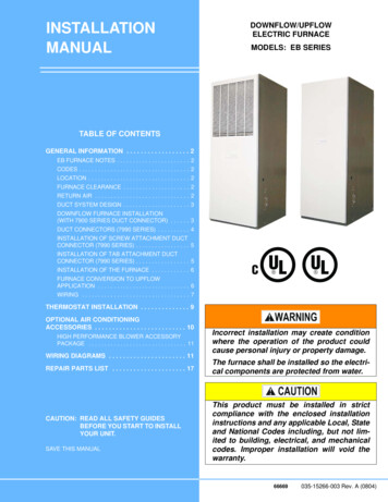
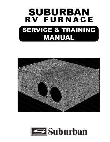
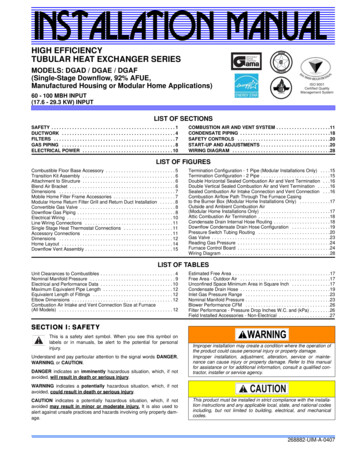
268882-UIM-A-0407DOWNFLOWFURNACEThe cooling coil must be installed in the supply air duct, downstream of the furnace. Cooled air must not flow over the heatexchanger.WARM AIR PLENUMWITH 1” FLANGESWhen the furnace is used in conjunction with a cooling coil, the coilmust be installed parallel with, or in the supply air side of the furnace toavoid condensation in the primary heat exchanger. When a parallel flowarrangement is used, dampers or other means used to control airflowmust be adequate to prevent chilled air from entering the furnace. Ifmanually operated, the damper must be equipped with means to prevent the furnace or the air conditioner from operating unless the damperis in full heat or cool position.FIBERGLASSINSULATIONFIBERGLASS TAPEUNDER FLANGECOMBUSTIBLE FLOORBASE ACCESSORYThe duct system must be properly sized to obtain the correct airflowfor the furnace size that is being installed.Refer to Table 3 and the furnace rating plate for the correct riserange and static pressuresIf the ducts are undersized, the result will be high duct static pressures and/or high temperature rises which can result in a heatexchanger OVERHEATING CONDITION. This condition can resultin premature heat exchanger failure, which can result in personalinjury, property damage, or death.FLOOR BASE AND DUCTWORK INSTALLATIONDownflow Combustible Floor BaseInstallations on combustible materials require the use acombustible floor base shown in Figure 1.The floor base must be secured to the floor. A supply airduct plenum with 1" (2.54 cm) flange is installed through theopening provided. The supply air duct is then secured to theduct system with screws and sealed to prevent leaks. Donot shoot screws through the flanges of the supply air ductinto the top of the combustible floor base. Install the furnace on thecombustible floor base so that the corners of the furnace are parallelwith the corner brackets of the floor base. Follow the instructions supplied with the combustible floor base accessory.This combustible floor base can be replaced with a matching coolingcoil, properly sealed to prevent leaks. Follow the instructions suppliedwith the cooling coil cabinet for installing the cabinet to the duct connector. Refer to the installation instructions for additional information.When replacing an existing furnace, if the existing plenum is not thesame size as the new furnace then the existing plenum must beremoved and a new plenum installed that is the proper size for the newfurnace.FIGURE 1: Combustible Floor Base AccessoryThe duct system is a very important part of the installation. If the ductsystem is improperly sized the furnace will not operate properly.The ducts attached to the furnace plenum, should be of sufficient sizeso that the furnace operates at the specified external static pressureand within the air temperature rise specified on the nameplate.IMPORTANT: Fabricate and install an inspection door in the plenumbase below the unit to allow an annual inspection of the heat exchangers. The inspection door can be fabricated by the following method.1.2.Cut a rectangular opening in the plenum base.A sheet metal plate can be made that completely covers the opening in the base.3. The plate must be secured with screws.4. This plate must be sealed to prevent leaks.To properly design the ductwork for the building, refer to the ASHRAEFundamentals Handbook, Chapter on “DUCT DESIGN” or a companythat specializes in Residential, Modular, and HUD Home duct designs.The supply air temperature MUST NEVER exceed the MaximumSupply Air Temperature, specified on the nameplate.Operating the furnace above the maximum supply air temperaturewill cause the heat exchanger to overheat, causing premature heatexchanger failure. Improper duct sizing, dirty air filters, incorrectmanifold pressure, incorrect gas orifice and/or a faulty limit switchcan cause the furnace to operate above the maximum supply airtemperature. Refer to SECTIONS II, III and XI for additional information on correcting the problem.IMPORTANT: If the supply air duct is being connected to the furnacewithout the use of an accessory duct connector, then a transition ductmust be installed with flanges or tabs that are securely attach andsealed to the supply air duct and to the base of the furnace. The transition duct must have insulation between the transition duct and any combustible material.The transition duct must be the same dimensional size as the rectangular opening in the base of the furnace.Unitary Products Group5
268882-UIM-A-0407Downflow Air Conditioning Coil CabinetAttachment to StructureThe Cooling Coil Cabinet can be used in place of the combustible floorbase for downflow installations on combustible materials. The furnaceshould be installed with the cooling coil cabinet specifically intended fordownflow applications. The cooling coil cabinet must be sec
this furnace. Refer to the furnace rating plate or SECTION IV of these instructions. 2. Install this furnace only in a location and position as specified in SECTION I of these instructions. 3. A gas-fired furnace for installation in a residential garage must be installed as specified in SECTION I of these instructions. 4.