Transcription
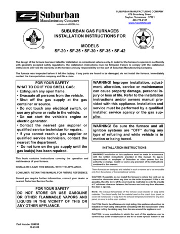
SUBURBAN MANUFACTURING COMPANY676 Broadway StreetDayton, Tennessee 37321423-775-2131www.rvcomfort.comSUBURBAN GAS FURNACESINSTALLATION INSTRUCTIONS FORMODELSSF-20 SF-25 SF-30 SF-35 SF-42The design of the furnace has been listed for installation in recreational vehicles only. In order for the furnace to operate in conformitywith generally accepted safety regulations, the installation instructions must be followed. Failure to comply with the installationinstructions will void the warranty on the furnace and any responsibility on the part of Suburban Manufacturing Company.The furnace was inspected before it left the factory. If any parts are found to be damaged, do not install the furnace. Immediatelycontact the transportation company and file a claim.FOR YOUR SAFETYWHAT TO DO IF YOU SMELL GAS: Extinguish any open flame. Evacuate all persons from the vehicle. Shut off the gas supply at the gascontainer or source. Do not touch any electrical switch, oruse any phone or radio in the vehicle. Do not start the vehicle’s engine orelectric generator. Contact the nearest gas supplier orqualified service technician for repairs. If you cannot reach a gas supplier orqualified service technician, contact thenearest fire department. Do not turn on the gas supply until thegas leak(s) has been repaired.This book contains instructions covering the operation andmaintenance of your furnace.INSTALLER: LEAVE THIS MANUAL WITH THE APPLIANCE.CONSUMER: RETAIN THIS MANUAL FOR FUTURE REFERENCE.Should you require further information, contact your dealer ornearest Suburban Service Center.FOR YOUR SAFETYDO NOT STORE OR USE GASOLINEOR OTHER FLAMMABLE VAPORS ANDLIQUIDS IN THE VICINITY OF THIS ORANY OTHER APPLIANCE.WARNING! Improper installation, adjustment, alteration, service or maintenancecan cause property damage, personal injury or loss of life. Refer to the installationinstructions and/or owners manual provided with this appliance. Installation andservice must be performed by a qualifiedinstaller, service agency or the gas supplier.WARNING! Be sure the furnace and allignition systems are “OFF” during anytype of refueling and while vehicle is inmotion or being towed.INSTALLATION INSTRUCTIONSWARNING! Installation of this appliance must be made in accordancewith the written instructions provided in this manual. No agent,representative or employee of Suburban or other person has theauthority to change, modify or waive any provision of the instructionscontained in this manual.These furnaces are designed and installed in such a manner as to be removableonly from the exterior of the recreational vehicle.CAUTION: If possible, do not install the furnace to where the vent can becovered or obstructed when any door on the trailer is opened. If this is notpossible, then the travel of the door must be restricted in order to providea 6” minimum clearance between the furnace vent and any door wheneverthe door is opened.NOTE: The exhaust temperature of this furnace could discolor or warp somematerials. You should verify that the material used on the coach door, panel, orcover will not discolor or warp from the exhaust temperature whenever any door,panel, or cover is in the open position.CAUTION: Due to the differences in vinyl siding, this appliance should not beinstalled on vinyl siding without first consulting with the manufacturer of thesiding or cutting the siding away from the area around the appliance vent.CAUTION: In any installation in which the vent of this appliance can becovered due to the construction of the RV or some special feature of thePart Number 20463810-23-08
RV such as slide out, pop-up etc. always insure that the appliance cannotbe operated by setting the thermostat to the positive “OFF” position andshutting off all electrical and gas supply to the appliance. Never operatefurnace with vent covered.It is important that adequate return air be provided to assure normal heating andoperation of the furnace. Failure to provide the minimum return air will causeerratic furnace cycling. Refer to the chart shown below for minimum return airrequirements.CAUTION: This furnace was shipped from the factory set up for the gasconnection to be made at the right rear of the unit as illustrated in Figure1. If you wish to make gas connection through the top of cabinet, you mustremove furnace from cabinet and turn gas inlet fitting 90 CLOCKWISE.DO NOT TURN FITTING COUNTER-CLOCKWISE, this will loosen fitting andresult in a gas leak.ModelReturn Air RequirementsMinimum Free (unobstructed) AreaSF-20/25/30/35SF-42WARNING! Hold manifold firmly when turning elbow to prevent anyforce from being inserted on the valve and to prevent any leaks fromdeveloping. Be sure to check all fittings for leaks including the inlet andoutlet on the valve before reinstalling furnace into cabinet. Correct allleaks immediately. NOTE: The furnace must be in operation to properlycheck for leaks.55 Sq. In.142 Sq. In.**May be reduced to 88 sq. in. min. if 5 ducts are used.TABLE 1NOTE: Return air must be from within the living area of the coach.NOTE: RV’s that have a wall of separation to a cargo area (Toy Box) to transportinternal combustion engine vehicles must not have return air openings from thisarea.NOTE: These furnaces must be installed and vented as described in this manualso that the negative pressure created by the air circulating (return air) fan cannotaffect the combustion air intake or venting of any other appliance. It is imperativethat the products of combustion be properly vented to the atmosphere and thatall combustion air supplied to burner be drawn from the outside atmosphere.(See Installing Vent Assembly.)A. INSTALLATION DIRECTLY AGAINST OUTER PANEL OF COACH(See Figure 1) (Panel supplied by installer)Maximum wall thickness for this type installation is 2”.NOTE: Do not install the furnace with the vent facing toward the forward end ofthe coach.1. Locate the furnace near lengthwise center of the coach.2. Choose a location for installation out of the way of wires, pipes, etc., whichmight interfere with the installation. Adhere to the minimum clearances from thecabinet to combustible construction as listed in Table 2. Refer to Figure 3 forillustration of furnace clearances.IMPORTANT: If this furnace is to be connected to a common duct system alsoserving a cooling unit, a manual or automatic damper is required to preventany cold conditioned air from circulating back into the furnace. Cold air passingover the furnace combustion chamber during the operation of the cooling unitcan result in the formation of condensation inside the furnace combustionchamber. This condensation may promote corrosion and premature failure ofthe combustion chamber.NOTE: These furnaces shall be installed so the electrical components areprotected from water.3. When an appliance is installed directly on carpeting, tile or other combustiblematerial, other than wood flooring, the appliance shall be installed on a metal orwood panel extending the full width and depth of the appliance. If preferred, thecarpeting, tile or combustible materials, other than wood may be cut away thefull length and depth of the appliance plus the appliance minimum clearances tocombustibles. (See Table 2.)These furnaces are design certified for propane/LP gas only. Do not attempt toconvert to natural gas.4. Cut an opening through the inner wall. This will allow the rear of the furnaceto be installed against the outer panel of the coach.Gas supply pressure for purposes of input adjustment:Minimum - 11” W.C.*Maximum - 13” W.C. *(W.C.* - Water Column).5. Locate center lines for exhaust and intake, as shown in Figure 1.6. Cut two 2-1/4” diameter holes through the outer panel of the coach. (SeeFigure 1.)In the U.S.A., the installation of the furnace must be in accordance with localcodes and regulations. In the absence of local codes and regulations, refer tothe latest edition of:7. Put furnace in place, making sure that rear of the furnace cabinet is as closeto outer panel of the coach as possible and still assure proper vent tube overlap.(See Installing Vent Assembly.)1. Standard for Recreational Vehicles NFPA 1192.2. National Fuel Gas Code ANSI Z223.1.8. Secure furnace to the floor using the two (2) holes provided in the furnacecabinet. (See Figure 4).3. Furnace must be electrically grounded in accordance with the latest edition ofthe National Electrical Code NFPA 70.9. Be sure furnace is secured within furnace cabinet. (See Figure 4).10. Install vent assembly. (See instructions for installing vent.)In Canada, the furnace must be installed in accordance with:B. INSTALLATION NOT AGAINST OUTER PANEL OR SKIN AND “X”DIMENSION GREATER THAN 1 ½”(See Figure 2) (Exterior panel supplied by installer)1. Standard CSA Z240.0.2-08 Recreational Vehicles.2. CSA Standard Z240.6.2-08Recreational Vehicles.C22.2 NO.148-08 Electrical Requirements forMaximum wall thickness for this type installation is 2”.3. Standard Z240.4.2-08 Installation Requirements for Propane Appliances andEquipment in Recreational Vehicles.1. Locate the furnace near lengthwise center of the coach.2. Choose a location for installation out of the way of wires, pipes, etc, whichmight interfere with the installation. Adhere to the minimum clearances fromcabinet to combustible construction as listed in Table 2. Refer to Figure 3 forillustration of furnace clearances.4. CAN/CGA-B149 Installation Codes.5. Any applicable local codes and regulations.This unit is equipped with an electric igniter device that has an energyconsumption of .1 amp @ 12 volts D.C.3. When an appliance is installed directly on carpeting, tile or other combustiblematerial, other than wood flooring, the appliance shall be installed on a metal orwood panel extending the full width and depth of the appliance. If preferred, thecarpeting, tile or combustible materials, other than wood may be cut away thefull length and depth of the appliance plus the appliance minimum clearances tocombustible. (See Table 2.)WARNING! Extension tubes cannot be used. If you try to extend the vent,it will result in improper installation which could cause unsafe furnaceoperation.4. Determine “X” dimension as shown in Figure 2. The tubes supplied withthe furnace will accommodate an installation range for “X” from o-1 ½”. If “X”dimension is greater than 1 ½”, then special vent tubes as charted in Figure 2must be ordered.There are three (3) methods described below for installing the furnace.Regardless of the method you choose, we require an opening be provided inthe exterior of the trailer or motor home for free, unobstructed removal of thefurnace. This exterior, removable panel or wall section of the trailer or motorhome must be a minimum of 17-3/4 x 8.2
WARNING ! Do not alter, cut, or otherwise modify the vent tubes assupplied by Suburban. Doing so could result in inadequate intake ofcombustion air or improper venting of furnace haust andIntake Tube5. After determining “X” dimension, complete the furnace installation 1”0”0”0”0”0”3/8”6. Locate center lines for exhaust and intake tubes as shown in Figure �3/8”7. Cut two 2-3/4” diameter holes through the outer panel or outer skin. (SeeFigure 2.)8. Put furnace in place, making sure that rear of furnace cabinet is as closeto inner wall section of the coach as possible and still assure proper vent tubeoverlap. (See Installing Vent Assembly.)-NOTE0” MEANS TO SPACER BUMPSCLEARANCE FROM DUCTS TOCOMBUSTIBLE MATERIAL - 1/4” (See Figure 3)9. Secure furnace to the floor using the two (2) holes provided in the furnacecabinet. (See Figure 4.)TABLE 210. Slide furnace into cabinet. Be sure furnace is secured within furnace cabinet(See Figure 4.)INSTALLING VENT ASSEMBLY11. Install vent assembly. (See instructions for installing vent.)The vent outlet must be installed so it is in the same atmospheric pressure zoneas the combustion air intake. The exhaust and intake tubes must be installedfrom the outside, pass through the RV skin and slide onto the furnace exhaustand intake.C. INSTALLATION USING THE FURNACE ACCESS DOOR SUPPLIED BYSUBURBAN (See Figure 4)Maximum wall thickness for this type installation is 2”.WARNING! Discard the vent assembly that came with the furnace. Thevent cap assembly supplied with the vertical mounting kit must beused. Suburban recommends all vents be installed using the rain shieldsupplied.1. Locate the furnace near lengthwise center of coach.2. Choose a location for installation out of the way of wires, pipes, etc., whichmight interfere with the installation. Adhere to the minimum clearances from thecabinet to combustible construction as listed in Table 2. Refer to Figure 3 forillustration of furnace clearances.Do not alter the vent assembly supplied with this furnace. Anymodifications will result in improper installation which could causeunsafe furnace operation.3. When an appliance is installed directly on carpeting, tile or other combustiblematerial, other than wood flooring, the appliance shall be installed on a metalor wood panel extending the full width and depth of the appliance. If preferred,the carpeting, tile or combustible maters, other than wood may be cut away thefull length and depth of the appliance plus the appliance minimum clearances tocombustibles. (See Table 2.)CAUTION! Combustion air must not be drawn from the living area. All airfor combustion must be drawn from the outside atmosphere. All exhaustgases must be vented to the outside atmosphere - never inside the RV.Therefore, it is essential to insure that the vent cap and tube assembliesare properly installed.4. After furnace location has been determined, cut an opening 18-7/32 x 8-9/32”through the inner coach wall and the outer wall (skin) of the coach.1. Apply caulking to RV skin behind vent cap as shown in Figure 1. Apply caulkinggenerously around perimeter of vent cap and across center as shown.5. Caulk around opening as illustrated. Apply generously. The purpose of thecaulking is to seal the back side of the door frame and the coach skin watertight.2. Insert intake tube through RV skin and slide it onto the furnace intake (SeeFigure 1.) Minimum tube overlap of 1/2” is required.3. Insert vent cap exhaust tube through RV skin and slide it onto the furnaceexhaust (See Figure 1.) Minimum tube overlap of 1 1/4” is required.6. Secure frame to outer wall (skin) through the holes in the frame. Screwsshould be used. (See Figure 4.) NOTE: Do not place screws into the holesrequired for mounting the door.4. Attach vent cap assembly to outer skin of RV with the six (6) screws provided.Do not install vent assembly upside down. The word “Suburban” must be rightside up.7. Slide furnace in place. The back of the furnace should be installed againstor as close as possible to the flange on the door frame. (See illustration.) Thefurnace must maintain 1/2” overlap on the intake and 1-1/4” overlap on theexhaust.CONNECTING GAS SUPPLY8. Secure furnace to the floor using the two (2) holes provided in the furnacecabinet. (See Figure 4.)CAUTION: This furnace was shipped from the factory set up for the gasconnection to be made at the right rear of the unit as illustrated in Figure 1.If you wish to make gas connection through the top of cabinet, you mustremove furnace from cabinet and turn gas inlet fittings 90 CLOCKWISE.DO NOT TURN FITTING COUNTER-CLOCKWISE, this will loosen fitting andresult in a gas leak.9. Slide furnace into cabinet. Be sure furnace is secured within furnace cabinet.(See Figure 4.)10. Position furnace access door over the frame. Secure the door to the coachskin. Be sure the coach skin is of sufficient strength to keep furnace access doorin place and insure a tight seal. It may be necessary to build a wood or metalframe around the opening in order to provide adequate strength for securingdoor.WARNING! Hold manifold firmly when turning elbow to prevent anyforce from being inserted on the valve and to prevent any leaks fromdeveloping. Be sure to check all fitting for leaks including the inlet andoutlet on the valve before reinstalling furnace into cabinet. Correct allleaks immediately. NOTE: The furnace must be in operation to properlycheck for leaks.CAUTION: The screws provided with the door may not be of sufficientlength and size for all applications and it may be necessary for the installerto substitute screws in order to adequately secure the furnace accessdoor.Connect the gas supply to the furnace at the manifold, following the suggestionsoutlined below. It will be necessary to hold the flare fitting on the furnace manifoldwhen connecting or loosening gas line.11. Install vent assembly. (See instructions for installing vent.)NOTE: The compound used on threaded joints must be resistant to liquefiedpetroleum (LP) gas.NOTE: The appliance must be disconnected from the gas supply piping systemduring any pressure testing of that system at test pressure in excess of 1/2PSIG.3
E. Avoid making a lot of turns in the duct system. The straighter the duct system,the better the performance of the furnace.The appliance must be isolated from the gas supply piping during any pressuretesting of the gas supply piping system at test pressure equal to or less than1/2 PSIG.F. Maintain a minimum of 1/4” clearance where ducts pass through anycombustible construction, such as coach cabinetry. (See Figure 3.) NOTE: ULlisted duct materials can be 0” clearance.1. A 3/8” male flare connection is provided for gas line hookup. Some standardsmay require the use of a manual shut off valve in the gas line external to thefurnace cabinet.G. Do not install air boosters in the duct system. Such devices will cause thefurnace to cycle on limit and to have erratic sail switch operation.2. In order to maintain a check of gas supplied pressure to the furnace, Suburban advisesthe installer to provide the 1/8” NPT plug tap for test gauge connection immediatelyupstream of the gas supply connection to the furnace and that it be readily accessible.NOTE: After installation of the furnace and duct system is completed, adjustmentsmust be made to obtain a temperature rise within the range specified on theRating Plate.3. After the furnace has been connected to the gas supply, all joints must bechecked for leaks.INSTALLING THERMOSTATWARNING! Never check for leaks with an open flame. Turn on the gasand apply soapy water to all joints to see if bubbles are formed.The thermostat used with this unit must have NO voltage output to return legwhen there is not a call for heat or in the “OFF” setting.CONNECTING ELECTRICAL SUPPLYLocate the room thermostat approximately 4-1/2 feet above the floor on aninside bulkhead where it is not affected by heat from any source except room air.Connect thermostat wiring to the blue wires on right side of furnace. (See wiringdiagram.) If your furnace is equipped with a thermostat that has an adjustableanticipator, the anticipator should be set at .7 amps. If you desire longer heatingcycles, adjust the anticipator to a higher setting. If you desire shorter heatingcycles, adjust the anticipator to a lower setting. Adjustments to the anticipatorsetting should be made in .5 amp increments.CAUTION: This furnace is designed for negative ground 12 volt D.C.system only. Do not attempt to alter the furnace for a positive groundsystem or connect the furnace directly to 115 volts A.C. Damage to furnacecomponent parts will occur. Connect only to a protected circuit fused fornot more than 20 amps.Be sure all wiring to the furnace is of heavy enough gauge to keep the voltagedrop through it to a minimum and to provide enough power for start-up surge.No. 12 gauge wire is recommended. If any of the original wire that is suppliedwith the appliance must be replaced, it must be replaced with type 105 C or itsequivalent.PREVENTIVE MAINTENANCEWARNING! If the user of this appliance fails to maintain it in thecondition in which it was shipped from the factory or if the appliance isnot used solely for its intended purpose or if appliance is not maintainedin accordance with the instructions in this manual, then the risk of afire and/or the production of carbon monoxide exists which can causepersonal injury, property damage or loss of life.Power supply connections are to be on the right side of the furnace. The wiresare color coded, red for positive ( ) and yellow for negative (-). This polaritymust be observed so the furnace motor will run the proper direction of rotation toinsure correct air delivery. (See wiring diagram.)If the furnace power supply is to be from a converter, we recommend that theconverter system used to power the furnace be wired in parallel with the battery.This will serve two purposes:CAUTION: Label all wires before disconnecting for servicing. Properpolarity must be observed so the furnace motor will run with the properdirection of rotation to insure correct air delivery. (See wiring diagram).1. Provide a constant voltage supply to the furnace.2. Filter any A.C. spikes or volt surges.CAUTION: Label all wires prior to disconnection when servicing controls.Wiring error can cause improper and dangerous furnace operation.Always verify proper operation of furnace after servicing.CONNECTING DUCTS TO FURNACEYour furnace should be inspected by a qualified service agency yearly beforeturning the furnace on. Particular attention should be given to the followingitems.The following duct requirements must be followed in order to assure properoperation of the furnace:A. The minimum open duct areas listed below must be maintained throughoutentire duct system including through register:MODELSIDE DUCTSMin. OpenDuct AreaMin No.Ducts UsedDuctSizeTOPDUCTBOTTOMDUCTMin. OpenDuct AreaMin. OpenDuct AreaSF-2025 SQ. IN.24”56 SQ. IN.56 SQ. IN.SF-2536 SQ. IN.34”56 SQ. IN.56 SQ. IN.SF-3036 SQ. IN.34”56 SQ. IN.56 SQ. IN.SF-3548 SQ. IN.44”56 SQ. IN.56 SQ. IN.SF-4248 SQ. IN.44”56 SQ. IN.*72 SQ. IN.1. Inspect furnace installation and vent termination to be sure furnace isproperly secured in place (see Installation Instructions), that vent terminatesto the atmosphere, and that vent tubes overlap properly (see Installing VentAssembly.)2. Inspect chamber and venting to assure that these components are physicallysound without holes or excessive corrosion and that the installation and/or reinstallation is in accordance with Suburban’s installation instructions. (Referenceinstallation manual supplied with furnace.)WARNING! It is imperative that the products of combustion be properlyvented to atmosphere and that all combustion air supplied to burner bedrawn from outside atmosphere.3. Check the base on which furnace is mounted. Be sure it is physically sound,void of any sagging, deterioration, etc.*SF-42 Bottom Duct requires use of Bottom Duct Kit, Part No. 520753NOTE: Ducts terminating in a dead air space (like holding tankcompartments or cargo areas (Toy Boxes) with no means for return airrecirculation should not be counted in the required duct area. Also ducts2” in diameter or smaller should not be counted in the required duct area.4. Inspect furnace, the venting, ducting and gas piping to furnace for obvioussigns of deterioration. Correct any defects at once.5. Inspect combustion chamber for restrictions in exhaust or intake. It isimperative that the flow of intake combustion air and the flow of exhaust gasesbeing expelled to the outside atmosphere not be obstructed. Any soot or loosedebris should be blown out using compressed air. (See Figure 7.)B. No outlet register is to be placed within 18” of the return air opening. Anyregister installed at 18” should never be toward the return air opening. If a registeris installed on a wall 90 degrees to the return air, it can be less than 18”.C. Make the duct connections at the furnace cabinet tight. Loose connectionswill result in overheating of the component parts on the furnace and a reductionof the heated air flow through the duct system.6. Inspect all gaskets. If any gaskets show signs of leakage or deterioration,replace them. Safe operation of the furnace depends on all gaskets being tight.7. Inspect return air inlet openings to the furnace. Remove any restrictions toassure adequate air flow.D. Avoid making any sharp turns in the duct system. Sharp turns will increasethe static pressure in the plenum area and could cause the furnace to cycle.You, as the owner/user, should inspect the furnace monthly during theheating season for presence of soot on vent. Operating the furnace under thiscondition could lead to serious property damage, personal injury or loss of life.4
INSTALLATION AND REMOVAL OF UNITINSTALLED FROM INSIDEIf soot is observed on the vent, immediately shut the furnace down and contacta qualified service agency.Listed below are several safety related items that you should follow during theheating season to assure continued safe operation of the furnace.TO REMOVE1. Disconnect power supply at furnace.1.Inspect furnace venting. Venting must be free of obstructions, void of soot, andproperly terminated to the atmosphere. (See Installing Vent Assembly.)2. Remove vent cap assembly.3. Disconnect gas connections.WARNING! Do not install screens over the vent for any reason. Screenswill become restricted and cause unsafe furnace operation. Accessoriesare being marketed for RV products which we do not recommend.For your safety, only factory authorized parts are to be used on yourfurnace4. Remove cabinet front (2 screws).5. Remove tie-down screw from center of unit and remove furnace from cabinet.TO INSTALL2. Periodically inspect the vent for obstructions or presence of soot. Soot isformed whenever combustion is incomplete. This is your visual warning that thefurnace is operating in an unsafe manner. If soot is present, immediately shutfurnace down and contact your dealer or a qualified service person.1. Slide unit into cabinet. NOTE: Care must be taken in routing wiring to back ofcabinet and outside of cabinet.3. Keep furnace clean. More frequent cleaning may be required due to excessivelint from carpeting, bedding material, etc. It is imperative that control compartments,burners and circulating air passageways of the appliance be kept clean.3. Reinstall cabinet front.4. The motor is permanently lubricated and requires no oiling.5. Check gas connections for leaks using a soap and water solution. Correct anygas leaks immediately.2. Reinstall tie-down screw.4. Connect gas line.5. Keep the furnace area clear of any combustible materials, gasoline or otherflammable vapor and liquids.6. Reinstall vent cap assembly.6. Before operating furnace, check the location of the furnace vent to make sureit will not be blocked by the opening of any door on the trailer. If it can be blocked,do not operate the furnace with the door open.INSTALLATION AND REMOVAL OF UNITWHEN OPTIONAL BACK IS USEDTO REMOVE7. Do not restrict the flow of combustion air or the warm air circulation to thefurnace. To do so could cause personal injury and/or death.1. Break power to furnace.8. Never operate the furnace if you smell gas. Do not assume that the smell of gasis normal. Any time you detect the odor of gas, it is to be considered life threateningand corrected immediately. Extinguish any open flames including cigarettes andevacuate all persons from the vehicle. Shut off gas supply at LP gas bottle. (Seesafety notice on front cover of this manual.)2. Remove vent cap assembly.3. Remove optional back.4. Disconnect power supply at furnace.9. Immediately shut furnace down and call a service agency if furnace cycleserratically or delays on ignition.5. Disconnect power supply plug from module board.6. Disconnect electrode wire from module board.WARNING! Should overheating occur, or the gas supply fail to shut off,shut off the manual gas valve to the appliance before shutting off theelectrical supply.7. Remove the two (2) screws securing module board and panel assembly tofirewall and pull out assembly. EXERCISE CARE NOT TO DAMAGE BOARD.10. Never attempt to repair damaged parts. Always have them replaced by aqualified service agency.NOTE: This will allow more room for making the gas connections at the flarefitting. It will be necessary to hold the flare fitting with a wrench when tightening orloosening the gas line.11. Never attempt to repair the furnace yourself. Seek the help of a qualifiedservice person.8. Remove gas line.12. Never restrict the ducting installed by your trailer manufacturer. To do so couldcause improper furnace operation.9. Remove tie-down screw at blower base and remove furnace from cabinet.TO REINSTALL13. Do not install air boosters in the duct system. Such devices will cause thefurnace to cycle and to have erratic sail switch operation.1. Slide unit into cabinet and secure with screw at base of blower.14. Clothing or other flammable material should not be placed on or near theappliance.2. Connect gas line.3. Check gas connections for leaks using a soap and water solution. Correct anygas leaks immediately.15. Always follow the operating instructions. Do not deviate from the step-by-stepprocedures.4. Reinstall module board and panel assembly.16. Do not use this appliance if any part has been submerged under water.Immediately call a qualified service technician to inspect the appliance andto replace any part of the control system and any gas control that has beensubmerged under water.5. Reconnect electrode wire to board6. Reconnect power supply to board.17. When considering add-on rooms, porch or patio, attention must be given tothe venting of your furnace. For your safety, do not terminate furnace vent insideadd-on rooms, screen porch or onto patios. Doing so will result in products ofcombustion being vented into the room or occupied areas.7. Reconnect power to furnace. NOTE: If this connection was made inside thecabinet, care must be exercised to prevent wires from coming in contac
Put furnace in place, making sure that rear of the furnace cabinet is as close to outer panel of the coach as possible and still assure proper vent tube overlap. (See Installing Vent Assembly.) 8. Secure furnace to the floor using the two (2) holes provided in the furnace cabinet. (See Figure 4). 9. Be sure furnace is secured within furnace .

