Transcription
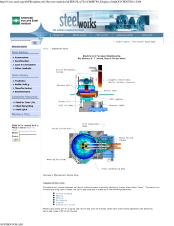
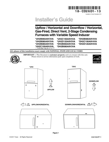
1 8 - CD1 9 D4 - 2 6Installer’s GuideUpflow/ Horizontal — Downflow/ Horizontal,Gas-Fired Furnaces, “Fan AssistedCombustion A*UE1B060A9361A*May be "A" or 0A9451A*DE1C100A9601A*DE1D120A9601AALL phases of this installation must comply with NATIONAL, STATE AND LOCAL CODESIMPORTANT — This Document is customer property and is to remain with this unit.Please return to service information pack upon completion of work.For VENT SIZING INFORMATION see:USA —National Fuel Gas Code . ANSI Z223.1/ NFPA 54 (latest version)CANADA —Natural Gas Installation Code . CAN/ CGA-B149.1 (latest version)Propane Installation Code . CAN/ CGA-B149.2 (latest version)USA/ CANADA ALTERNATE —Category I Venting Guide . Pub. No. 18-CH23D1-2Upflow/ Horizontal*Downflow/ Horizontal**Horizontal Conversion for these furnaces may be left or right side rotation.A341789P04
Installer’s GuideSAFETY SECTIONThe following safety practices and precautions must befollowed during the installation, servicing, and operation of this furnace.1. Use only with the type of gas approved for this furnace. Refer to the furnace rating plate.2. Install this furnace only in a location and position asspecified in “Location and Clearances” (page 4) ofthese instructions.3. Provide adequate combustion and ventilation air tothe furnace space as specified in “Air for Combustion and Ventilation” (pages 8 & 9) of these instructions.4. Combustion products must be discharged outdoors.Connect this furnace to an approved vent systemonly, as specified in the “Venting” section (pages 1315) of these instructions.5. Never test for gas leaks with an open flame. Use acommercially available soap solution made specifically for the detection of leaks to check all connections, as specified in “Gas Piping” (page 16) of theseinstructions.6. Always install the furnace to operate within thefurnace’s intended temperature-rise range with aduct system which has an external static pressurewithin the allowable range, as specified on the unitrating plate. Airflow with temperature rise for cfmversus static is shown on pages 23 and 24 of thisdocument.7. When a furnace is installed so that supply ductscarry air circulated by the furnace to areas outsidethe space containing the furnace, the return airshall also be handled by a duct(s) sealed to the furnace casing and terminating outside the space containing the furnace.8. A gas-fired furnace for installation in a residentialgarage must be installed as specified in “Locationand Clearances” section (page 4), of these instructions.9. The furnace may be used for temporary heating ofbuildings or structures under construction onlywhen the following conditions have been met:a. The furnace venting system must be completeand installed per manufacturer’s instructions.b. The furnace is controlled only by a room thermostat (no field jumpers).c. The furnace return air duct must be completeand sealed to the furnace and clean air filters arein place.d. The furnace input rate and temperature risemust be verified to be within nameplate marking.e. 100% of the furnace combustion air requirementmust come from outside the structure. 2011 TraneAll Rights Reservedf. The furnace return air temperature range is between 55 and 80 degrees Fahrenheit.g. Clean the furnace, duct work, and componentsupon substantial completion of the constructionprocess, and verify furnace operating conditionsincluding ignition, input rate, temperature riseand venting, according to the manufacturer’s instructions.10. This product must be gas piped by a LicensedPlumber or Gas Fitter in the Commonwealth ofMassachusetts.! WARNING CARBON MONOXIDE POISONING HAZARDFailure to follow the steps outlined below for eachappliance connected to the venting system beingplaced into operation could result in carbon monoxidepoisoning or death.The following steps shall be followed for each applianceconnected to the venting system being placed intooperation, while all other appliances connected to theventing system are not in operation:1. Seal any unused openings in the venting system.2. Inspect the venting system for proper size and horizontalpitch, as required in the National Fuel Gas Code,ANSI Z223.1/NFPA 54 or the CAN/CGA B149Installation Codes and these instructions. Determinethat there is no blockage or restriction, leakage,corrosion and other deficiencies which could cause anunsafe condition.3. As far as practical, close all building doors and windowsand all doors between the space in which theappliance(s) connected to the venting system arelocated and other deficiencies which could cause anunsafe condition.4. Close fireplace dampers.5. Turn on clothes dryers and any appliance not connectedto the venting system. Turn on any exhaust fans, suchas range hoods and bathroom exhausts, so they areoperating at maximum speed. Do not operate a summerexhaust fan.6. Follow the lighting instructions. Place the appliance being inspected into operation. Adjust the thermostat soappliance is operating continuously.7. If improper venting is observed during any of the abovetests, the venting system must be corrected inaccordance with the National Fuel Gas Code,ANSI Z221.1/NFPA 54 and/or CAN/CGA B149Installation Codes.8. After it has been determined that each applianceconnected to the venting system properly vents wheretested as outlined above, return doors, windows, exhaustfans, fireplace dampers and any other gas-fired burningappliance to their previous conditions of use.18-CD19D4-26
Safety signal words are used to designate a degree orlevel of seriousness associated with a particular hazard.The signal words for safety markings are WARNING andCAUTION.a. WARNING indicates a potentially hazardous situation which, if not avoided, could result in death orserious injury.b. CAUTION indicates a potentially hazardous situationwhich, if not avoided, may result in minor or moderateinjury. It is also used to alert against unsafe practicesand hazards involving only property damage.! WARNING FIRE OR EXPLOSION HAZARDFailure to follow the safety warnings exactly could result in serious injury, death or property damage.Improper servicing could result in dangerous operation, serious injury, death, or property damage.GENERAL INSTALLATION INSTRUCTIONSThe manufacturer assumes no responsibility for equipment installed in violation of any code or regulation.It is recommended that Manual J of the Air Conditioning Contractors Association (ACCA) or A.R.I. 230 be followed in estimating heating requirements. When estimating heating requirements for installation at Altitudes above 2000 ft., remember the gas input must bereduced (See GAS INPUT ADJUSTMENT).Material in this shipment has been inspected atthe factory and released to the transportationagency without known damage. Inspect exteriorof carton for evidence of rough handling in shipment. Unpack carefully after moving equipmentto approximate location. If damage to contents isfound, report the damage immediately to the delivering agency.Installer’s GuideContentsSafety Section2Installation Instructions3General Installation InstructionsLocation and ClearancesOutline DrawingsUpflow InstallationDownflow InstallationsHorizontal InstallationAir for Combustion and VentilationDuct ConnectionsReturn Air FiltersGeneral Venting InstructionsVenting into a Masonry ChimneyField Wiring DiagramsElectrical ConnectionsGas PipingSequence of Operation34577781011121315141617Start-up and Adjustment17Preliminary InspectionsCombustion and Input CheckHigh Altitude DerateLighting InstructionsControl and Safety Switch Adjustment1717191920Abnormal Conditions20IFC Error Flash Codes21Periodic Servicing Requirements22Airflow tables23Codes and local utility requirements governing theinstallation of gas fired equipment, wiring, plumbing,and flue connections must be adhered to. In the absence of local codes, the installation must conform withlatest edition of the National Fuel Gas Code ANSIZ223.1 National Installation Code, CAN/CGA B149.1.The latest code may be obtained from the American GasAssociation Laboratories, 400 N. Capitol St. NW,Washington D.C. 20001.1-800-699-9277 or www.aga.orgThese furnaces have been classified as Fan AssistedCombustion system CATEGORY I furnaces as requiredby ANSI Z21.47 “latest edition” and CAN/CGA 2.3.Therefore they do not require any special provisions forventing other than what is indicated in these instructions. (Category I defined on page 11).18-CD19D4-263
Installer’s Guide! CAUTION To prevent shortening its service life, the furnaceshould not be used as a “Construction Heater” duringthe finishing phases of construction until the requirements listed in item 9, a-g of the safety section of thispublication have been met. Condensate in the presence of chlorides and fluorides from paint, varnish,stains, adhesives, cleaning compounds, and cementcreate a corrosive condition which may cause rapid deterioration of the heat exchanger.! WARNING These furnaces are not approved or intended for installation in manufactured (mobile) housing, trailers, orrecreational vehicles.Failure to follow this warning could result in propertydamage, personal injury, or death.! CAUTION Do NOT install the furnace in a corrosive or contaminated atmosphere.! WARNING Do NOT install the furnace directly on carpeting, tile or othercombustible material other than wood flooring. For verticaldownflow application, subbase (BAYBASE205) must beused between the furnace and combustible flooring. Whenthe downflow furnace is installed vertically with a cased coil,a subbase is not required.! WARNING LOCATION AND CLEARANCESThe location of the furnace is normally selected by thearchitect, the builder, or the installer. However, before thefurnace is moved into place, be sure to consider the followingrequirements:1. Is the location selected as near the chimney or vent andas centralized for heat distribution as practical?2. Do all clearances between the furnace and enclosureequal or exceed the minimums stated in Clearance Tableon the Outline Drawings.3. Is there sufficient space for servicing the furnace andother equipment? A minimum of 24 inches front accessibility to the furnace must be provided. Any access door orpanel must permit removal of the largest component.4. Are there at least 3 inches of clearance between thefurnace combustion air openings in the front panel andany closed panel or door provided?5. Are the ventilation and combustion air openings largeenough and will they remain unobstructed? If outside airis used, are the openings set above the highest snowaccumulation level? (See the Air for Combustion andVentilation section)6. Allow sufficient height in supply plenum above thefurnace to provide for cooling coil installation, if thecooling coil is not installed at the time of this furnaceinstallation.7. A furnace shall be installed so electrical components areprotected from water.8. If the furnace is installed in a residential garage, itmust be installed so that the burners, and the ignitionsource are located not less than 18 inches above the floorand the furnace must be located or protected to avoidphysical damage from vehicles.EXPLOSION HAZARD!PROPANE GAS IS HEAVIER THAN AIR AND MAYCOLLECT IN ANY LOW AREAS OR CONFINEDSPACES. IN ADDITION, ODORANT FADE MAY MAKETHE GAS UNDETECTABLE EXCEPT WITH A WARNING DEVICE. IF THE GAS FURNACE IS INSTALLEDIN A BASEMENT, AN EXCAVATED AREA OR ACONFINED SPACE, IT IS STRONGLY RECOMMENDED TO CONTACT A GAS SUPPLIER TO INSTALL A GAS DETECTING WARNING DEVICE INCASE OF A GAS LEAK.NOTE: The manufacturer of your furnace does NOT testany detectors and makes no representations regardingany brand or type of detector.418-CD19D4-26
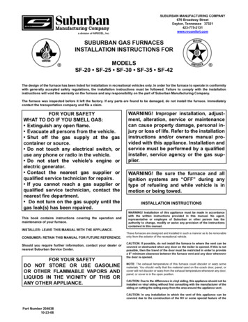
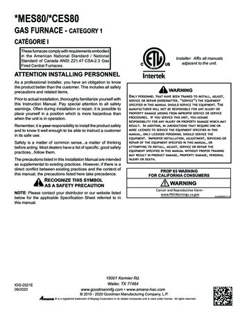
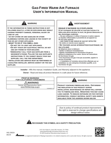
(ALL DIMENSIONS ARE IN INCHES)*UE1-A OUTLINE DRAWINGFrom Dwg. C340781 Sh. 1 Rev. 16Installer’s Guide18-CD19D4-265
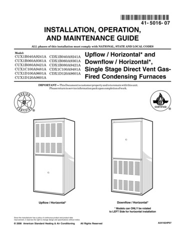
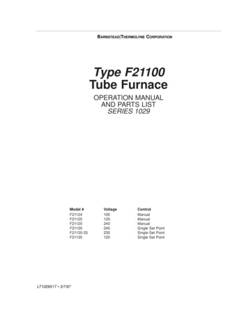
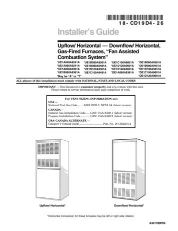
621"* Prefix letter may be "A" or "T"** Suffix letter may be "A" through DE1B060A9361A***DE1B080A9451A***DE1B100A9451A**DIM "A"14-1/2"MODEL*DE1A060A9361A**(ALL DIMENSIONS ARE IN INCHES)*DE1-A OUTLINE DRAWING15-5/16"13-1/16"9-5/8"9-5/8"DIM "B"23-1/4"19-3/4"16-1/4"13-1/4"23"19-1/2"16"13"DIM "D"From Dwg. 21C340804 Sh. 1 Rev. 13DIM "C"Installer’s Guide18-CD19D4-26
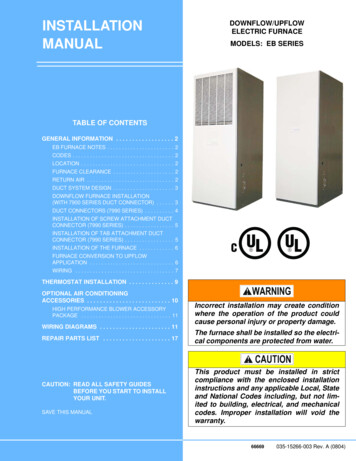
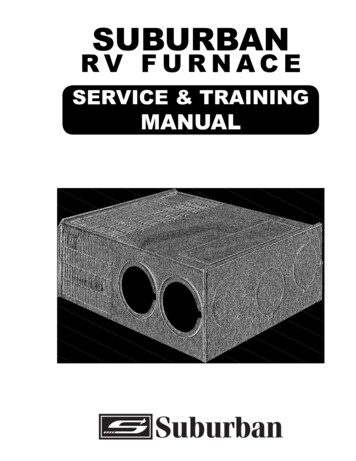
Installer’s GuideUPFLOW INSTALLATIONThe coil is always placed downstream of the furnace airflow. Apply gasket material (duct seal field supplied) toALL mating surfaces between the furnace and the coilcase.1Seal with fieldsuppliedsealant orgasketCASECO DILUPFU FLORN WACEVERTICALINSTALLATIONS:DOWNFLOW INSTALLATIONS! WARNING Do NOT install the furnace directly on carpeting, tile orother combustible material other than wood YBASE205) must be used between the furnace andcombustible flooring. When the downflow furnace is installed vertically with a cased coil, a subbase is not required.2REQUIRED FLOOR OPENING: (DOWNFLOW)See Figure 3 and Table 2345678901234567890121234567890123456A 456B BLE 1FLOOR OPENING PLENUM OPENINGCABINETRETURNWIDTH DUCT WIDTH"A""B""C""D"14-1/2"13-1/4"13-5/8" 20-1/8" 12-5/8"19-3/8"17-1/2"16-1/4"16-5/8" 20-1/8" 15-5/8"19-3/8"21"19-3/4"20-1/8" 20-1/8" 19-1/8"19-3/8"24-1/2"23-1/4"23-5/8" 20-1/8" 22-5/8"19-3/8"HORIZONTAL INSTALLATIONThe coil and furnace must be fully supported when usedin the horizontal position.Three brackets (with screws) are included withdownflow furnaces for installation to stabilize and secure the furnace and TXC cased coil in the horizontalposition. See Figure 4.IMPORTANT:The 2/4TXC cased coil must be placed downstream of thefurnace. In horizontal installations, the apex of the coilmay point either toward or away from the furnace. Seethe 2/4TXC coil Installer's Guide for more details.The cased coil is secured to the furnace and both thefurnace and the cased coil must be properly supported.The brackets mount using the rear screws on the coilcase and use the screws provided to secure the bracketto the furnace. The remaining bracket is placed asclose to center as possible (horizontally) between thecoil case front and the furnace bottom channel (fordownflow/horizontal furnace). Use four of the screwsprovided to secure the bracket. The upflow furnace,4 CASED COIL CONNECTIONBRACKET FOR DOWNFLOWFURNACE IN HORIZONTALDOWNFLOW ONLYconverted to horizontal, aligns and attaches the TXCcoil as in Figure 1. However, the coil requires additionalsupport. This furnace may be installed in an attic orcrawl space in the horizontal position by placing the furnace on the left or right side (as viewed from the frontin the upright position). The horizontal furnace installation in an attic should be on a service platform largeenough to allow for proper clearances on all sides andservice access to the front of the furnace (See ClearanceTable on Outline Drawings and Figure 5).18-CD19D4-267
Installer’s GuideIf the furnace is suspended using perforated steel strap(plumber’s strap), it must be supported at all four corners and in the middle at the front of the furnace. Theforward most screw on the side of the furnace may beused to connect the strapping (See Figure 6). Line contact is only permissible between lines formed by the intersection of the top and two sides of the furnace casingand the building joists, studs, or framing.5TYPICAL UPFLOW/HORIZONTAL ATTIC INSTALLATIONA cutout is provided on both sides of the downflow furnace cabinet to allow a 90 elbow to be attached insidethe cabinet and the vent piping to connect there. Inhorizontal, the downflow furnace may be ventedthrough the top of the cabinet if needed. In vertical configuration, the downflow furnace may be vented usingthe side cabinet cutouts. This venting configurationcould be used if an electronic air cleaner is installed.When the downflow furnace is vented throughthe left side of the furnace cabinet in horizontalor vertical configuration, Type B vent pipe mustbe used within the cabinet.6UNCONFINED50 CU. FT. OR MOREPER 1000 BTU/HR. INPUTALL EQUIP. INSTALLED88CONFINEDLESS THAN 50 CU. FT.PER 1000 BTU/HR. INPUTALL EQUIP INSTALLEDTypical Suspended Upflow/Horizontal Furnace7AIR FOR COMBUSTION AND VENTILATIONAdequate flow of combustion and ventilating air mustnot be obstructed from reaching the furnace. Air openings provided in the furnace casing must be kept free ofobstructions which restrict the flow of air. Airflow restrictions affect the efficiency and safe operation of thefurnace. Keep this in mind should you choose to remodel or change the area which contains your furnace.Furnaces must have a free flow of air for proper performance.Provisions for combustion and ventilation air shall bemade in accordance with “latest edition” of Section 5.3,Air for Combustion and Ventilation, of the NationalFuel Gas Code, ANSI Z223.1, or Sections 7.2, 7.3 or 7.4of CAN/ CGA B149 Installation Codes, and applicableprovisions of the local building codes. Special conditionscreated by mechanical exhausting of air and fireplacesmust be considered to avoid unsatisfactory furnace operation.Furnace locations may be in “confined space” or “unconfined space”. Unconfined space is defined in Table 2 andFigure 7. These spaces may have adequate air by infiltration to provide air for combustion, ventilation, anddilution of flue gases. Buildings with tight construction(for example, weather stripping, heavily insulated,caulked, vapor barrier, etc.), may need additional airprovided as described for confined space.Confined spaces are installations with less than 50 cu.ft. of space per 1000 BTU/hr input from all equipmentinstalled. Air for combustion and ventilation requirements can be supplied from inside the building as inFigure 9 or from the outdoors, as in Figure 10.1. All air from inside the building as in Figure 9: Theconfined space shall be provided with two permanent openings communicating directly with an additional room(s) of sufficient volume so that the combined volume of all spaces meets the criteria for anunconfined space. The total input of all gas utilization equipment installed in the combined spaceshall be considered in making this determination.Refer to Table 3, for minimum open areas required.2. All air from outdoors as in Figure 10: The confinedspace shall be provided with two permanent openings, one commencing within 12 inches of the topand one commencing within 12 inches of the bottom of the enclosure. The openings shall communicate directly, or by ducts, with the outdoors orspaces (crawl or attic) that freely communicate withthe outdoors. Refer to Table 3, for minimum openareas required.18-CD19D4-26
Installer’s GuideTABLE 2MINIMUM AREA IN SQUARE FEET FORUNCONFINED SPACE INSTALLATIONS0WITH 8 FOOT CEILINGFURNACE MAXIMUMMINIMUM AREA IN SQUARE FEETBTUH / INPUT RATINGOF UNCONFINED 500625750875TABLE 3MINIMUM FREE AREA IN SQUARE INCHESEACH OPENING (FURNACE 000100,000120,000140,000Air From OutsideAir Duct10152025303520304050607093. The following types of installations will require use ofOUTDOOR AIR for combustion, due to chemical exposures:* Commercial buildings* Buildings with indoor pools* Furnaces installed in commercial laundry rooms* Furnaces installed in hobby or craft rooms* Furnaces installed near chemical storage areas.Exposure to the following substances in the combustion air supply will also require OUTDOOR AIR forcombustion:* Permanent wave solutions* Chlorinated waxes and cleaners* Chlorine based swimming pool chemicals* Water softening chemicals18-CD19D4-26* Deicing salts or chemicals* Carbon Tetrachloride* Halogen type refrigerants* Cleaning solvents (such as perchloroethylene)* Printing inks, paint removers, varnish, etc.* Hydrochloric acid* Cements and glues* Antistatic fabric softeners for clothes dryers* Masonry acid washing materials9
Installer’s GuideDUCT CONNECTIONSAir duct systems should be installed in accordance withstandards for air conditioning systems, National FireProtection Association Pamphlet No. 90. They shouldbe sized in accordance with ACCA Manual D or whichever is applicable.Central furnaces, when used in connection with coolingunits, shall be installed in parallel or on the upstreamside of the cooling units to avoid condensation in theheating element, unless the furnace has been specifically approved for downstream installation. With a parallel flow arrangement, the dampers or other meansused to control flow of air shall be adequate to preventchilled air from entering the furnace, and if manuallyoperated, must be equipped with means to prevent operation of either unit unless the damper is in full heator cool position.On any job, flexible connections of nonflammable material may be used for return air and discharge connections to prevent transmission of vibration. Thoughthese units have been specifically designed for quiet, vibration free operation, air ducts can act as soundingboards and could, if poorly installed, amplify the slightestvibration to the annoyance level.When the furnace is located in a utility room adjacentto the living area, the system should be carefully designed with returns which minimize noise transmissionthrough the return air grille. Although these winter airconditioners are designed with large blowers operatingat moderate speeds, any blower moving a high volumeof air will produce audible noise which could be objectionable when the unit is located very close to a livingarea. It is often advisable to route the return air ductsunder the floor or through the attic. Such design permits the installation of air return remote from the living area (i.e. central hall).When the furnace is installed so that the supply ductscarry air circulated by the furnace to areas outside thespace containing the furnace, the return air shall alsobe handled by a duct(s) sealed to the furnace and terminating outside the space containing the furnace.Minimum return air/“air entering” temperaturefor the furnace is 55 F.Where there is no complete return duct system, the return connection must be run full size from the furnace toa location outside the utility room, basement, attic, orcrawl space.Do Not install return air through the back of thefurnace cabinet.10RETURN AIR DUCT CONNECTIONAll return air duct systems should provide for installation of return air filters.NOTE:On upflow 5 ton airflow models, if the airflow requirement exceeds 1800 CFM, these models will require return air openings and filters on both sides; OR 1 sideand the bottom; OR just the bottom.1. Set the furnace in place.2. For side return installations on upflow models, remove the insulation around the opening in theblower compartment.3. The side panels on upflow furnaces include locatingnotches which may be used as guides for cutting anopening for return air. Refer to Figure 11 and theoutline drawing on page 4 for duct connection dimensions for various furnaces.4. If a 3/4" flange is to be used for attaching the air inlet duct, add to cut where indicated by solid lines inFigure 11. Cut corners diagonally and bend outwardto form flange.5. If flanges are not required, and a filter frame is installed, cut along knockout guidelines.6. Upflow Furnaces: filter retainer brackets are factory supplied for bottom return. Use the filter retainer brackets on either side or on bottom if filteris to be used within the furnace cabinet.If bottom return opening is not used, fabricate andinstall a sheet metal plate in the bottom of the furnace cabinetqLOCATINGNOTCHESPROVIDEDFOR SIDERETURNCUTOUTUPFLOW FURNACE ONLYCUT OUTFORSIDEFILTER****FRONTof Furnace*SEE OUTLINE DRAWINGDownflow Furnaces: Brackets are factory supplied to mount filters in the return air duct work.When the upflow furnace is installed in the horizontal right or left application and a return duct is attached to the top side as shown in Figure 12, remove the filter from the furnace and install in a remote location.18-CD19D4-26
Installer’s GuideDo not install the filter in the return duct directlyabove the furnace in horizontal applications.! WARNING Do NOT install the filter in the return duct directlyabove the furnace in horizontal applications. Installthe filter remotely. Installing the filter directly abovethe furnace in horizontal applications may causeproperty damage, serious injury or death.! WARNING TO PREVENT INJURY OR DEATH DUE TO CONTACTWITH MOVING PARTS, TURN THE POWER TO THEFURNACE OFF BEFORE SERVICING FILTERS.When the upflow furnace is installed in the horizontal right or left application and a close coupled (lessthan 36") return duct is attached to the bottom sideof the furnace as shown in Figure 12, securely attach a 1/2" mesh metal hardware cloth protectivescreen to the inside bottom of the filter grill to prevent personal injury from contacting movingparts when reaching into the return openingto replace the filter.REMOVE FILTER FROM UPFLOWFURNACE WHEN RETURN DUCT ISATTACHED TO FURNACE TOP SIDE(HORIZONTAL LEFT OR RIGHTAPPLICATIONS) AS SHOWN.wFILTERClose coupled (less than 36")return (filter directly beneath bottomside return) not recommended due tonoise considerations. If used, securelyattach 1/2" mesh metal hardware clothprotective screen to the inside bottom offilter grill.Close coupled (less than 36") return (filter directlybeneath bottom side return) is not recommendeddue to noise considerations.7. Connect the duct work to the furnace. See OutlineDrawing for supply and return duct size and location. Flexible duct connectors are recommended toconnect both supply and return air ducts to the furnace.If only the front of the furnace is accessible, it isrecommended that both supply and return air plenums are removable.18-CD19D4-268. When replacing a furnace, old duct work should becleaned out. Thin cloths should be placed over theregisters and the furnace fan should be run for10 minutes. Don’t forget to remove the cloths before you start the furnace.RETURN AIR FILTERFilters are field supplied for these furnaces. These furnaces require high velocity type air filters which may belocated within the furnace blower compartment for UPFLOW furnaces in either a BOTTOM or SIDE (left sideor right side) return air inlet. See Figures 13 and 14.Some filters may need to be trimmed for side or bottomfilter use.NOTE:On upflow 5 ton airflow models, if the airflow requirement exceeds 1800 CFM, these models will require return air openings and filters on both sides; OR 1 sideand the bottom; OR just the bottom.Downflow furnace filters must be located outside thefurnace cabinet. Typical installations are shown on page10 in Figure 15. Tables 5 and 6 on page 11, provide information for installation of the filter retaining bracketsshipped with downflow furnaces.TABLE 4MODELCABINETWIDTHREQUIREDFILTER SIZE A14-1/2"1 - 14 X 25 X 0A9361A17-1/2"1 - 17 X 25 X 1*UE1C100A9481A*UE1C100A9601A21"1 - 20 X 25 X 1*UE1D120A9601A*UE1D140A9601A24-1/2"1 - 24 X 20 X 1* Prefix letter may be "A" or "T"** Note: On 5 ton air flow models, if the airflow requirementexceeds 1800 CFM, these models will require filters on bothsides; OR 1 side and the bottom; OR just the bottom.MODELNUMBERCABINETWIDTHREQUIREDFILTER 1C100A9601A*DE1D120A9601A14-1/22 - 14X20X12 - 16X20X12 - 16X20X12 - 16X20X12 - 16X20X117-1/22124-1/211
Installer’s GuideTYPICAL DOWNFLOW FURNACERETURN AIR FILTER INSTALLATIONSeTABLE LTERSIZE- 14X20X1- 16X20X1- 16X20X1- 16X20X1FILTER BRACKETLOCATION *12-7/8"14-3/8"13-1/8"11-5/8"* Location dimension is from end of duct to the screw holes for the bracket.TABLE 6Typical Filters of Upflow in URN FILTER ACCESS FILTER ACCESSDUCTOPENING OPENING WIDTHDIMENSION "A" DIMENSION /4"22"14"GENERAL VENTING INSTRUCTIONSAirflowrwAirfloVENT PIPINGThese furnaces have been classified as Fan-AssistedCombustion System, Category I furnaces under the “latest edition” provisions of ANSI Z21.47 and CAN/CGA 2.3standards. Category I furnaces operate with a non-positive vent static pressure and with a flue loss of not lessthan 17 percent.NOTE:If desired, a side wall termination can be accomplishedthrough the use of an “add-on” draft inducer. The inducer must be installed according to the inducermanufacturer’s instructions. Set the barometric pressure relief to achieve -0.02 inch water column.NOTE:When the downflow furnace is vented through the leftside of the furnace cabinet using the provided cutout,Type B vent piping must be used.The furnace shall be connected to a factory builtchimne
followed during the installation, servicing, and opera-tion of this furnace. 1. Use only with the type of gas approved for this fur-nace. Refer to the furnace rating plate. 2. Install this furnace only in a location and position as specified in "Location and Clearances" (page 4) of these instructions. 3.