Transcription
Application Note: Virtex-4 and Virtex-5 FPGAsArchitecting ARINC 664, Part 7 (AFDX)SolutionsXAPP1130 (v1.0.1) May 22, 2009SummaryAuthor: Ian Land and Jeff ElliottEach new generation of commercial aircraft has grown more complex, especially with the heavyreliance of fly-by-wire and the associated avionics. As more systems are designed into airframes,traditional point-to-point wiring schemes are no longer practical. The designers of the AirbusA380 searched for a solution to reduce the amount of wiring, increase bandwidth, and make useof commercial-off-the-shelf (COTS) technology where possible. ARINC Specification 664(ARINC 664), Part 7 is the result of that search.This application note provides users with a detailed overview of the architecture and function ofavionics full-duplex switched Ethernet (AFDX) as defined in the specification ARINC 664,Part 7 ([Ref 1]). In addition, a detailed description of how various functional blocks required foran AFDX end system can be mapped to both the Virtex -4 and Virtex-5 architectures isincluded.ARINC 664OverviewAFDX combines concepts taken from asynchronous transfer mode (ATM) and applies them to avariant of IEEE Std 802.3 (Ethernet). At the physical layer, AFDX consists of a star-topology, fullduplexed switched Ethernet (either 100BASE-TX or 100BASE-FX). This topology eliminates thecollision issue found in half-duplexed Ethernet.Note: For background on the development of AFDX, see “Appendix A: Background,” page 24.In addition, the network is profiled. In an airframe, all connection, addressing, and bandwidthrequirements for the entire network are known in advance. Each part of the network can betailored to the specific connection. The network profile is updated when there are any upgradesand changes to the electronics of the aircraft.At the protocol level, AFDX creates the concept of a virtual link (VL) — a point-to-point ormulticast connection through the network. The VL mimics the unidirectional connections foundin ARINC Specification 429 [Ref 2] (see also “ARINC 429,” page 24). Again, as the network isprofiled, the addressing and bandwidth requirements of each VL is defined in advance.Moreover, the network is deterministic with the latency for each connection known in advance.The traffic flow and shaping mechanisms help guarantee the latency, jitter, and bandwidth foreach link, providing the QoS required for avionics systems.The last issue to be addressed is robustness. AFDX relies on parallel, redundant networks toprovide an additional level of fault tolerance. Each data packet is sent across both networkssimultaneously. Redundancy management mechanisms ensure that only one copy of eachpacket is transmitted, and that sequential order of the packets is maintained.ARINC Specification 664 is divided into eight parts: Part 1, Systems Concepts and Overview [Ref 3] Part 2, Ethernet Physical and Data Link Layer Specifications Part 3, Internet-based Protocols and Services Part 4, Internet-based Address Structures and Assigned Numbers Part 5, Network Interconnection Services and Functional Elements Part 6, Reserved 2009 Xilinx, Inc. XILINX, the Xilinx logo, Virtex, Spartan, ISE, and other designated brands included herein are trademarks of Xilinx in the United States and other countries.PowerPC is a trademark of IBM Corp. and is used under license. All other trademarks are the property of their respective owners.XAPP1130 (v1.0.1) May 22, 2009www.xilinx.com1
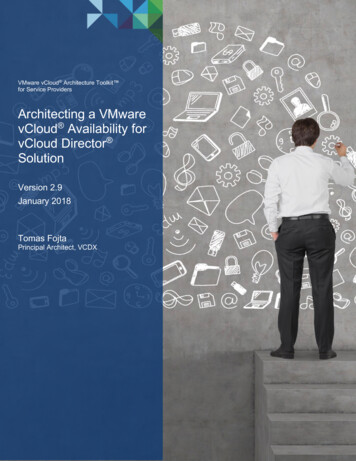
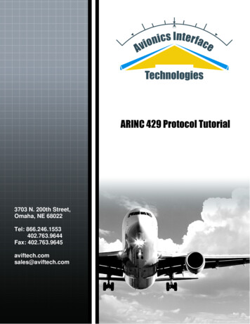
AFDX – The Details Part 7, Avionics Full Duplex Switched Ethernet (AFDX) Network Part 8, Upper Layer ServicesAFDX is defined by Part 7, along with IEEE Std 802.3 (Ethernet standard).AFDX – TheDetailsNetwork TopologyAn AFDX network consists of up to 24 end systems connected to a switch (Figure 1). Switchescan be cascaded to increase the capacity of the network. Total switch capacity is limited to4,096 VLs (including the routing of VLs either originating or terminating beyond end systemsconnected to that switch).Note: There is no explicit limit on the number of VLs an end system can support. The maximum numberis a function of the amount of required bandwidth of each VL and its maximum frame length.X-Ref Target - Figure emAFDXEnd SystemAFDXEnd SystemAFDXEnd AvionicsSubsystemAFDXEnd SystemAFDXEnd SystemAFDXEnd TxRxTxRxRxTxRxTxRxTxAFDXEnd TxTxTxTxRxTxAFDXEnd SystemAFDXEnd SystemAFDXEnd itchTxTxRxRxTxTxRxRxTxAFDXEnd SystemAFDXEnd SystemAFDXEnd bsystemX1130 01 030809Figure 1:AFDX Topology (Redundancy Not Shown)The network is profiled — all routes and addressing are predefined and contained in theconfiguration for both end systems and switches, simplifying network configuration.Transmitting end systems are responsible for enforcing bandwidth limits, and receiving endsystems manage redundancy. Switches are responsible for routing frames, policing bandwidth,and shaping traffic.XAPP1130 (v1.0.1) May 22, 2009www.xilinx.com2
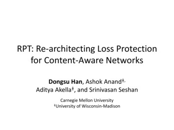
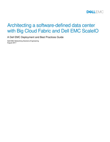
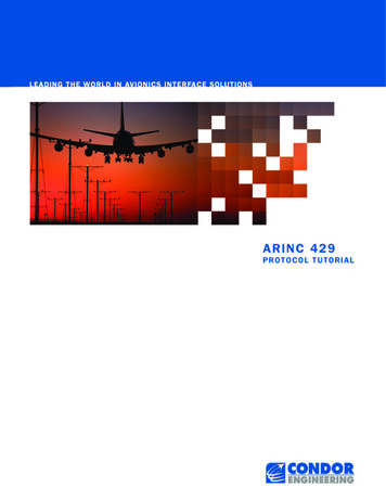
AFDX – The DetailsThere is no intra-switch communication (other than passing data frames) between redundant orcascaded switches. All routes are based upon the switch’s routing table.The standard (ARINC 664, Part 7) also allows for the mapping of other protocols over AFDX.For example, ARINC 429 links can be built across an AFDX network through the use ofconcentrators/protocol conversion modules.RedundancyTo increase the robustness of the system, an AFDX network consists of two redundantnetworks; each end system has two Ethernet ports (A and B), with A ports connected to switchA and B ports, which are connected to switch B (Figure 2). Identical frames are sent by the endsystem on both ports simultaneously. Each switch routes their frames independently to thedestination end systems. The receiving end system is responsible for managing the receptionof redundant frames, deleting duplicates and any out-of-order frames.X-Ref Target - Figure 2TxRxTxController TxARxTxRxTxRxTxAFDX SwitchNetwork ARxTxRxTxRxRxTxRxTx ControllerARxAFDXAvionicsSubsystem End SystemAFDXAvionicsEnd System SubsystemController TxBRxTxRxRxRxTxAFDX SwitchNetwork BTxTxTxRxTxRxTxRxTx ControllerBRxRxTxRxX1130 02 012309Figure 2:AFDX RedundancyNote: Redundancy is not required for all VLs and can be turned off for a given VL, provided a thoroughevaluation of the impact is completed.Frame FormatThe AFDX frame format (Figure 3) is compliant with IEEE Std 802.3 (Ethernet). The framecontains addressing for identifying source and destination end systems as well as the assignedvirtual link. AFDX frame length can vary from 64 to 1518 bytes (plus a 7-byte frame preamble,1 frame start byte, and 12-byte interframe gap (IFG), with a data payload between 1 and1471 bytes (payload must be padded to a minimum length of 17 bytes).X-Ref Target - Figure 3AFDX Frame7 BytesPreamble6 Bytes2 BytesStartDestination SourceFrameAddress AddressDelimiter0x800IPv41 Byte6 Bytes20 Bytes8 BytesIP Structure UDP Structure1–1471 BytesAFDX Payload0–16 Bytes 1 BytePaddingSN4 Bytes12 BytesFrameCheckSequenceInterFrameGapX1130 03 030809Figure 3:AFDX FrameThe one-byte frame sequence number is used to maintain ordinal integrity for frames of a givenVL as well as assist in detecting missing frames. During transmission, the sequence number isincremented by one for each VL frame, starting at 0 and wrapping at 255 to 1.Note: A sequence number of 0 is used to indicate a reset condition of the transmitting end system.XAPP1130 (v1.0.1) May 22, 2009www.xilinx.com3
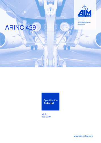
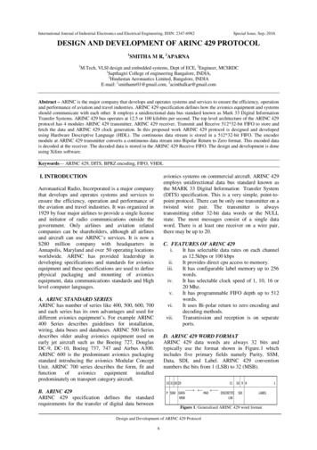
AFDX – The DetailsAddressingAt the data link layer, each VL is assigned a MAC address by the system integrator. The 48-bitMAC destination address (Figure 4) consists of 32 bits to constant field (identical for all endsystems in the network) and 16 bits to identify the VL. AFDX frames are routed by the switch toall destination end systems identified for the VL in the switch configuration.X-Ref Target - Figure 448 Bits32 Bits16 BitsConstant FieldVirtual Link IdentifierXXXX XX11 XXXX XXXX XXXX XXXX XXXX XXXXNNNN NNNN NNNN NNNNX1130 04 012309Figure 4:MAC Destination Address FormatThe 48-bit MAC source address (Figure 5) identifies the Ethernet controller of the end systemoriginating the frame. The first 24 bits of the address are set to a constant value. Following theconstant value is a 16-bit unique identifier for the controller set by the system integrator (ARINC664 provides only general guidance on setting this value). Following the 16-bit unique identifieris a 3-bit value used to identify which network the controller is connected to (001 for network Aand 010 for network B — all other values are not used). The final 5 bits are set to a constant:0 0000.X-Ref Target - Figure 548 Bits24 Bits16 Bits3 Bits5 BitsConstant FieldUser-Defined IdentifierInterface IDConstant Field0000 0010 0000 0000 0000 0000NNNN NNNN NNNN NNNNNNN0000 0X1130 05 012309Figure 5:MAC Source Address FormatNote: The focus of this application note is on the data link and physical layers. For more informationabout IP addressing within the network, refer to the ARINC 664, Part 7 standard.Virtual LinksThe goal of ARINC 664, Part 7, is to preserve point-to-point links while reducing the amount ofwiring. The physical point-to-point links of ARINC 429 [Ref 2] are replaced by virtual links,connecting sensors and actuators with control units (Figure 6). VL links are time-divisionmultiplexed at the end system for transmission over the network.XAPP1130 (v1.0.1) May 22, 2009www.xilinx.com4
AFDX – The DetailsX-Ref Target - Figure 6VL2VL1VL2 VL3 stemAFDXEnd SystemAFDXEnd SystemAFDXEnd nicsSubsystemAFDXEnd SystemAFDXEnd SystemAFDXEnd RxTxRxTxRxRxTxRxRxRxRxTxAFDXEnd TxTxTxVL3TxRxTxAFDXEnd SystemAFDXEnd SystemAFDXEnd bsystemRxVL1 xAFDXEnd SystemAFDXEnd SystemAFDXEnd bsystemVL2Figure 6:RxAFDXSwitchTxTxRxX1130 06 012309Virtual Links over an AFDX NetworkEach VL is guaranteed a specific maximum bandwidth as well as an end-to-end maximumlatency. The assigned bandwidth is controlled by the end system and enforced in the switch,where the latency is defined by the system integrator, bounded by the limits set in the standard(see “Latency,” page 8). In addition, a VL is assigned a maximum allowed frame size of LMAX.Note: In the switch specification section of the standard, LMAX is referred to as SMAX. In addition, thatsection specifies a minimum allowed frame size SMIN for each VL (see “Frame Filtering,” page 10).The total of all bandwidth assigned to VLs cannot exceed the total bandwidth available in thenetwork. Additionally, the demands on bandwidth at each switch must be known because eachswitch must handle VLs originating and terminating at attached end systems and any VLsbeing forwarded to other switches in the network.Each VL can be composed of up to four sub-VLs. Sub-VLs are used to handle less critical datawith less stringent bandwidth requirements (bandwidth guarantees apply only at the VL level).Data queues for each sub-VL are read in a round-robin fashion, with each frame containing dataXAPP1130 (v1.0.1) May 22, 2009www.xilinx.com5
AFDX – The Detailsonly from one sub-VL queue (any fragmentation has to be handled at the IP layer). After a framefor a sub-VL is created, that frame is handled by the network no differently than a VL frame.Note: Sub-VLs are an optional implementation, available to the end user as needed. Moreover, thestandard does not specify how sub-VLs are identified. Possibly a unique VL identifier can be assigned toeach sub-VL by the system integrator.End SystemsVirtual Link ManagementThe primary responsibility is the management of transmitting and receiving data for the virtuallinks. An end system can handle a maximum of 128 VLs and can be built to any neededconfiguration, for example, to transmit four VLs and receive six VLs, with one receive VL beingcomposed of three sub-VLs. A one-size-fits-all design is not required.For each VL and sub-VL, the end system must maintain a FIFO queue (sub-VLs FIFO queuesare read in a round-robin fashion to fill its assigned VL FIFO queue) — ordinal integrity oftransmitted frames must be maintained. The size of the VL/sub-VL queues is not specified bythe ARINC 664, Part 7, but the total of all queues for a given application (or partitions as definedby ARINC Specification 653 [Ref 4]) must be at least 8 kB (an application or partition can haveone or more VLs).For transmission, the end system is responsible for: Reading each VL queue. Incrementing the VL frame sequence number. Scheduling each frame for transmission to maintain the bandwidth guarantee within theallowed jitter. Transmitting redundant frames on both controllers A and B.On reception, the end system is responsible for: Deleting redundant frames and policing ordinal integrity. Separating data by VL and writing received frames to the appropriate queue.Note: The end system must continue to transmit frames even if there is a link failure.For a redundant VL reception, an end system should: When redundancy management is active, pass one copy of redundant data to the partition(see “Redundancy Management”). When redundancy management is not active, pass both copies of redundant data to thepartition.For a non-redundant VL reception, the end system should pass data from either channel to thepartition (redundancy management can be active or not).Bandwidth ControlThe bandwidth control mechanism varies the frame payload and frame transmission interval.Essentially, each VL is assigned a transmission time slot — a VL can transmit a frame within anassigned bandwidth allocation gap. A bandwidth allocation gap represents the minimum timeinterval (less allowed jitter) between the beginning of consecutive frames for a given VL(Figure 7); however, an end system can transmit frames from differing VLs within the limitsdefined by IEEE Std 802.3.Note: If no data is available for a VL at the next available bandwidth allocation gap, the end system is notrequired to transmit any data (in other words, an empty frame). Moreover, the bandwidth allocation gaprepresents the minimum interval for transmission — a VL can transmit data at a longer interval than itsassigned bandwidth allocation gap. Although not explicitly stated, the standard implies that framesexceeding the allocated bandwidth are dropped at the incoming AFDX port.XAPP1130 (v1.0.1) May 22, 2009www.xilinx.com6
AFDX – The DetailsX-Ref Target - Figure 7Bandwidth Allocation GapBandwidth Allocation GapJitterWindowJitterWindowBandwidth Allocation GapJitterWindowFrameFrameFrameX1130 07 012309Figure 7:Single VL Transmission within Set Bandwidth Allocation Gap and Defined JitterBandwidth allocation gaps range from a minimum of 1 ms to a maximum of 128 ms, the sizedetermined by Equation 1.kEquation 1Bandwidth Allocation Gap Size 2where k is an integer in the range of 0 to 7.The bandwidth allocation gap value for each VL is assigned by the system integrator, based on theneeds of the application, and stored in the configuration tables for the end system (and switch).Via the traffic shaping function/scheduler, the end system reads each VL queue as needed, thendetermines the optional transmission order, taking advantage of the allowed jitter in schedulingframes. Each frame is transmitted outside the limits set by the bandwidth allocation gap (less jitter)for its VL, respecting the proper interframe gap between frames from differing VLs (Figure 8).X-Ref Target - Figure 8IFG PreambleBandwidthAllocationGapVL1Bandwidth Allocation GapVL1JitterVL1Bandwidth Allocation GapVL1JitterVL1Frame VL1JitterVL1Frame VL1Frame VL2Frame VL1Frame VL2JitterVL2JitterVL2JitterVL2Bandwidth Allocation GapVL2Frame VL2Bandwidth Allocation GapVL2Bandwidth Allocation GapVL2X1130 08 012309Figure 8:Scheduling Two VL StreamsAn end system must be capable of transmitting data at the maximum frame rate supported bythe medium. Conversely, the end system must be able to receive and process frames at thatsame maximum rate.JitterThe traffic shaping function is allowed to introduce jitter when transmitting frames. This jitterallows the end system flexibility when transmitting simultaneous (or near simultaneous) framesfrom differing VLs.For AFDX, jitter is defined as the time between the beginning of the bandwidth allocation gapinterval and the first bit of the frame to be transmitted in that bandwidth allocation gap interval,measured at the transmitting end system. The standard allows for 40 μs of jitter as the result ofthe transmitting technology plus an amount based upon the bandwidth requirements of theVLs, limited to a maximum of 500 μs. The maximum allowed jitter is shown in Equation 2.XAPP1130 (v1.0.1) May 22, 2009www.xilinx.com7
AFDX – The Details where:( 20 L MAX ) 8 {Set of VLs }Jitter MAX 40 ----------------------------N BWEquation 2JitterMAX is in μs, limited to a maximum of 500 μs.LMAX is in bytes.NBW is the bandwidth of the transmission medium in bits per second.LatencyARINC 664, Part 7 does not specify a system-wide latency but does provide some limits at theend system and switch level.For an End SystemFor an end system, the standard limits the latency during reception to less than 150 μs. Duringtransmission, the maximum latency for a VL is defined as:Latency MAX ( frame p ) p bandwidth allocation gap Jitter MAX technological latency in transmission Equation 3where p represents the number of the frame in a sequence of a data burst, or fragmented data.For a single frame with evenly spaced data, p 1.For a SwitchThe standard defines latency for the switch as the elapsed time between the reception of thelast bit of the frame until the transmission of the last bit of the frame. Switch latency iscomposed of three parts: technological latency of the switching function, the configurationlatency due to switch loading, and the time required to transmit the frame on the medium.The standard specifies a limit only for the technological latency (less than 100 μs).Determining End System CapacityThe standard sets no limit on the number of VLs an end system can support and states that anend system must be able to transmit at the medium’s maximum frame rate. However, the endsystem must respect bandwidth limits and LMAX values for each VL as well as comprehend thetotal VL limit at the switch.The worst-case (minimum) number of VLs occurs when LMAX for each VL is 1,518 bytes andeach VL is assigned the maximum bandwidth (bandwidth allocation gap 1 ms). At 100 Mb/s,a frame of this size (1,518 bytes 20 bytes overhead) takes 123.04 μs to transmit. With eachVL respecting a bandwidth allocation gap of 1 ms, an end system could only handle eight VLs.Note: This is based on a unit analysis only. It is doubtful that an end system could effectively scheduletraffic from all eight, maximum-bandwidth, maximum-frame-length VLs. Thorough traffic modeling isrequired to determine the feasible maximum.Without considering limitations at the switch level, the best case (maximum) number of VLsoccurs when LMAX for each VL is 64 bytes, and each VL is assigned the minimum bandwidth(bandwidth allocation gap 128 ms). At 100 Mb/s, a frame of this size (64 bytes 20 bytesoverhead) takes 6.72 μs to transmit. With each VL respecting a bandwidth allocation gap of1 ms, an end system could handle 19,047 VLs — far exceeding the capacity of the switch.Limits o
The standard (ARINC 664, Part 7) also allows for the mapping of other protocols over AFDX. For example, ARINC 429 links can be built across an AFDX network through the use of concentrators/protocol conversion modules. Redundancy To increase the robustness