Transcription
Yan et al. EURASIP Journal on Wireless Communications and Networking(2020) ESEARCHOpen AccessDesign of UAV wireless power transmissionsystem based on coupling coil structureoptimizationYixin Yan, Wan Shi and Xiaobing Zhang*AbstractWith the development of unmanned aerial vehicle (UAV), it has been used in many fields, such as aerialphotography, military, and transportation. However, it is a challenge for charging due to its short battery life.Wireless charging has been considered as a good UAV solution. In this paper, we proposed a wireless powertransmission system (WPT) through inductive coupling and analyzed the power efficiency of the inductive coupling.The WPT included a charging station, which can provide energy through an induction coil array, and a portableenergy receiving device mounted on the base of the UAV. Moreover, the power efficiency was analyzed thoughthe equivalent circuit of WPT and the mathematical model of the power efficiency was established. The resultsshowed that the WPT can transfer energy to UAV with high power efficiency within a 30 mm lateral displacementrange.Keywords: Unmanned aerial vehicle, Wireless charging, Magnetic coupling resonance1 IntroductionIn recent years, the performance of unmanned aerial vehicle (UAV) is gradually optimized. Its application is expanded from military to civil use [1, 2], scientificresearch, and other fields [3–5]. UAV can be equippedwith many payloads, such as cameras, sensors, positioning systems [6–8]. These loads are often powered byhigh energy density lithium batteries, which can only lastfor 20–40 min [9–11]. The lithium battery limits thelength of UAV possible running length [12–15]. It is necessary for UAV continuously conduct inspections anddetection under working condition [16–18]. Therefore,it is important to elongate the running time of UAV[19]. Three potential methods are proposed to increasethe flight time of UAV. The first method is to build up anew type battery with higher UAV capacity [20], but thismethod will cause unexpected high body weight of* Correspondence: zhang xiaobing123@126.comElectronic Measurement and Control Laboratory, School of MeasurementControl and Communication Engineering, Harbin University of Science andTechnology, Harbin 150080, People’s Republic of ChinaUAV. It will indirectly reduce the loading efficiency [21–23]. The second method is to set up a base station, andthe UAV can exchange battery automatically in the basestation. This method can solve the problem of endurance of UAV [24]. However, this proposal is not practical because of its high cost and the complexity of thealgorithm. The third known method is to build a charging pile on UAV that can recharge the UAV directly.There are two ways to charge UAV: (1) build directcontact between the charging pile and UAV to chargeUAV directly. Although the transmission efficiency ofthis direct contact pile model is high [25], the unpredictable serious environmental factors will destabilize theentire system in the air. (2) Use wireless power transmission (WPT) technology with the coupling resonance between the coils to recharge UAV [26–28]. There areseveral not ideal factors that need to be taken into consideration. (A) The size of coupling device. (B) The actual load of UAV. (C) The energy safety. The mostimportant point is that WPT must consider the efficiency of power transmission. The inaccurate landing of The Author(s). 2020 Open Access This article is licensed under a Creative Commons Attribution 4.0 International License,which permits use, sharing, adaptation, distribution and reproduction in any medium or format, as long as you giveappropriate credit to the original author(s) and the source, provide a link to the Creative Commons licence, and indicate ifchanges were made. The images or other third party material in this article are included in the article's Creative Commonslicence, unless indicated otherwise in a credit line to the material. If material is not included in the article's Creative Commonslicence and your intended use is not permitted by statutory regulation or exceeds the permitted use, you will need to obtainpermission directly from the copyright holder. To view a copy of this licence, visit http://creativecommons.org/licenses/by/4.0/.
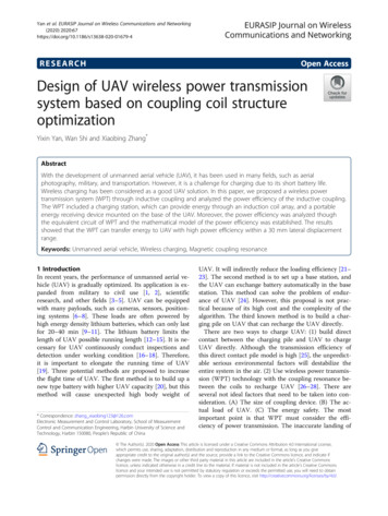
Yan et al. EURASIP Journal on Wireless Communications and Networkingthis system will lead to misaligned of coils, which will reduce the efficiency of WPT. There are many methodsare introduced to solve this problem. (A) Use automaticalignment landing procedure, image processing technology, and position technology to enhance the landing accuracy of UAV [29–31]. (B) Move transmitting coils toalign with airborne receiving coils through both the internal mechanical structure of the charging pile and theexternal sensor to improve the transmission efficiency[32, 33]. The position and sensor detection of UAV isoften affected by various environmental factors, whichlowers the landing accuracy of UAV [34].Those methods mentioned above cannot effectivelysolve the problem of low efficiency caused by the misalignment of the primary coil and the secondary coil.Solving the problem of low charging efficiency due tomisaligned coupling coils is the main challenge for enabling patrol drones to constantly check the workspace.The major point is to find a way to increase the transmission power efficiency when the coupling coil is misaligned. In this research, a new type of coupling coil isdesigned, which can improve the power and efficiency ofWPT even if the coupling device is offset.The main contributions of this paper include:1. The compensation circuits are analyzed in principle,and then formulas for those compensation circuitsare derived. According to those derived formulas, aSeries-Series compensation circuit is selected. Andthen, the inductance and capacitance value of thiscompensation circuit is calculated.2. This research builds a new type of coupling coilarray, and demonstrates its advantages by analyzingdata collected through experiments.(2020) 2020:67charged in an hour. Coil coupling is an important parameter, which can be improved by reducing air gap, toimprove the charging efficiency. The secondary coil thatset on the landing sled of UAV can reduce the verticalair gap between the primary and secondary coil, to improve the transmission efficiency. The secondary coil atthe receiver is designed as a small circular coil to facilitate the placement of the UAV above the sled. The primary coil of the transmitter is designed as anindependent coil array as shown in Fig. 1, and the primary coil is placed on the charging pile.The independent coil array design of the primary coilis essential, because it ensures enough coupling at alllanding positions. The working principle of the independent coil array is that when the UAV lands, the Bluetooth sensor on the charging pile detects the Bluetoothsignal of the UAV, monitors whether the UAV haslanded on principle of the independent coil array is thatwhen the UAV lands, and then the controller opens thecharging area and the primary coil is coupled to the secondary coil, and finally the UAV is charged through theprimary coil.In a typical WPT charging system, the voltage is adjusted before the charging link of the receiver. The voltage is adjusted at the transmitter region first to reducethe body weight and occupied space of system. Thestructure diagram of the whole WPT system is shown inFig. 2. The voltage at the transmitter is adjusted using adirect current (DC)/DC converter before inverter, andthen converts DC to alternating current (AC) throughinverter, and then low frequency part of the AC is filtered by a high-pass filter circuit, and the high frequencyAC is transmitted through the wireless coupling betweenthe coils. The receiver of the UAV receives energyThe rest of this paper is organized as follows. Section2 discusses the overall scheme design of WPT system.WPT system of UAV is designed and simulation resultsof the system are given in Section 3. The hardware ofthe system is designed in Section 4. Section 5 concludesthe paper with summary.2 The proposed scheme2.1 System modelThe WPT system of UAV is mainly composed of transmitter and receiver. The primary coil is arranged on thecharging pile, and the secondary coil is arranged on theUAV, and lithium battery is commonly used as energysource to provide voltage UAV. The wireless chargingsystem is built to use coil to transmit energy to the battery. For the general UAV, its power system is generallycomposed of three to six lithium batteries with capacitybetween 3 and 10Ah, which can provide up to 11.1 V to22.2 V. This type of lithium battery can be quickly fullyPage 2 of 13Fig. 1 Independent coil array
(2020) 2020:67Yan et al. EURASIP Journal on Wireless Communications and NetworkingFig. 2 Structure diagram of WPT systemthrough resonance magnetic coupling. Then the voltageof battery recovers through rectifying, filtering, and compensating circuits. In this way, the UAV can work efficiently and transmit medium range wireless power.2.2 WPT equivalent circuitWPT technology is a kind of near-field energy transfermethod, which transfers energy from power supply toload through magnetic resonance coupling coil withoutdirect ground electrical contact. The loose couplingtransformer is composed of two coils to build the magnetic resonance coupling coil of WPT. Based on theequivalent circuit theory, this paper models and analyzesthe WPT of magnetic coupling resonance, and optimizesthe charging distance, power, and efficiency parametersof UAV. The equivalent circuit of the whole WPT system is shown in Fig. 3. There are coil self-inductance L1and L2 between the coupling coils, mutual inductanceM, and coil self-resistance R1 and R2. Self-inductance,mutual inductance, and self-resistance cause the loss ofthe whole system. In order to reduce the AC loss causedby skin effect and proximity effect, the coupling coilshall be wound by copper stranded wire. The couplingcoefficient K of the coil is:MK ¼ pffiffiffiffiffiffiffiffiffiffiL1 L2ð1ÞA capacitor compensation network is added to thetransmitter and receiver to obtain continuously resonance and improve the power transmission performancePage 3 of 13of the system. As shown in Fig. 3, this circuit is a typicaltopology with Series-Series (S-S) compensation. At thetransmitter, a full bridge inverter composed of fourMOSFETs (Q1, Q2, Q3, Q4) is used to convert the DCvoltage into the AC voltage V1. At the receiver, thehigh-frequency voltage V2 transmitted through thecoupler is first rectified by a full bridge rectifier composed of D1, D2, D3, and D4. The output voltage afterrectification is filtered by a low-pass filter composed ofL3 and C3, and finally charges the battery.To facilitate the calculation and extraction of lumpedparameters, the circuit is simplified, as shown in Fig. 4.In the figure, RS is the resistance of the power supply, RLis the load resistance, R1, R2 represent the internal resistance of each coil, L1, L2 represent the equivalent inductance of the coil, C1, C2 represent the compensationcapacitance of the circuit, and M represents the mutualinductance between the primary and secondary coils.In Fig. 4, the self-impedance of the main circuit isexpressed as Z11, the expression is Z11 RS R1 j(ωL1 1/ωC1), the self-impedance of the secondary circuit isexpressed asZ22, and the expression is Z22 R2 RL j(ωL2 1/ωC2). The voltage equation of main circuit andsecondary circuit can be written as follows:fI 1 ðZ 11 jωΜÞ þ ðI 1 I 2 ÞjωΜ ¼ USI 2 ðZ 22 jωΜÞ þ ðI 2 I 1 ÞjωΜ ¼ 0ð2ÞFrom Eq. (2), the current equations of the main circuitand the secondary circuit can be deduced as follows:I1 ¼fZ 22 U SZ 11 Z 22 þ ðωΜÞ2jωΜU SI2 ¼Z 11 Z 22 þ ðωΜÞ2ð3ÞIt can be seen from the expression of the secondarycircuit current in formula (3) that the induced electromotive force is related to the angular frequency ω andthe mutual inductance coefficient M of the coil. Onlywhen the imaginary part of the current expression of thesecondary circuit is zero, the circuit is in resonance state,the current of the secondary circuit reaches the maximum value, and the load obtains the maximum power.Fig. 3 Circuit of WPT charging system with series-series (S-S) compensation
Yan et al. EURASIP Journal on Wireless Communications and Networking(2020) 2020:67Page 4 of 13the coupling coil will lead to the reduction of the effective transmission distance. Therefore, it is necessary tointroduce two other key parameters: quality factor Qand coupling factor K to discuss the transferperformance.According to the circuit theory, the quality factors ofthe coupling coil, Q1 and Q2, are as follows:Fig. 4 Simplified circuit with S-S compensationThe receiving power of the load and the transmissionefficiency of the system can be expressed by the following formula:!2ωMU S2P L ¼ I 2 RL ¼ð4ÞZ 11 Z 22 þ ðωΜ Þ2PLωM RL 100% ¼ P INZ 22 Z 11 Z 22 þ ðωΜÞ2 100%ωM 2 RL¼R2 þ RLη¼Q1 ¼ωL1R1 þ RSð6ÞQ2 ¼ωL2R2 þ RLð7ÞThe expressions of power and efficiency can be obtained by introducing formulas (1), (6), and (7) into Eqs.(4) and (5):PL ¼η¼2ð5ÞAs shown in Eq. (5), increasing the resonant frequencyω or the mutual inductance coefficient M can improvethe transmission efficiency of the system. If only increasing the resonant frequency will lead to the skin effect ofthe conductor, resulting in higher energy loss and lowerefficiency, but only increasing the mutual inductance ofU 2S RLk 2 Q1 Q2 ðR1 þ R2 ÞðR2 þ RL Þ 1 þ k 2 Q1 Q2 2RLk 2 Q1 Q2 R2 þ RL 1 þ k 2 Q1 Q2ð8Þð9ÞThe MATLAB simulation software is used to simulatethe received power and transmission efficiency, and thecurves of receiving power and transmission efficiencywith respect to quality factor Q and coupling factor Kare obtained, as shown in Figs. 5 and 6.As shown in Figs. 5 and 6, the transmission performance can be effectively improved only by making K, Q1,and Q2 achieve their maximum value in the resonantmagnetic coupling system with constant resonant frequency. However, it is difficult to improve the systemFig. 5 Influence curve of quality factor and coupling factor on received power
Yan et al. EURASIP Journal on Wireless Communications and Networking(2020) 2020:67Page 5 of 13Fig. 6 Influence curve of quality factor and coupling factor on transmission efficiencyperformance by increasing K, because the transmissionmedium is basically air. The system performance can beimproved in another way. Instead of increasing thecoupling coefficient by increasing the quality factor ofthe coil, the effective transmission distance is greatly improved, while receiving efficiency and transmission efficiency are improved. According to formula (6) and (7), itcan be seen that the quality factor is related to the working frequency ω, the coil self-induction L, and the coilinternal resistance R, and it does not change with otherparameters such as the relative position between thecoupling coils. Therefore, this paper focuses on the design of high-quality factor coil and the solution of coilmisalignment during UAV charging.Fig. 7 Four basic resonant compensation circuits2.3 Selection of compensation circuitCoupling coil is one of the key devices in wireless transmission. In the coupling coil, the air gap between thetransmitting coil and the receiving coil is large. In general, the coupling coefficient between the two coils isnot too large, so the efficiency of power transmission isextremely low under the excitation of 50 Hz signalsource. In order to make the radio transmission efficiency and power meet the requirements of use, capacitors are added to the primary and secondary circuits forcompensation, and the inductance and capacitancevalues of the primary and secondary circuits are adjustedat the same time, so that the two circuits have the sameresonance frequency, to achieve efficient transmission.
Yan et al. EURASIP Journal on Wireless Communications and Networking(2020) 2020:67Page 6 of 13Table 1 Total impedance of four kinds of resonantcompensation circuitsCompensation circuitInput impedanceS-Sω MjðωL1 ωC1 1 Þ þ RL þ jðωL2 S-PjðωL1 ωC1 1 Þ þ221ωC 2 Þ1P-SjωL1 þ1ω2 M2ω2 M2RjωL2 þjωC RL2 L þ1þjωC 1RL þ jðωL2 1 ÞωC 21P-PjωL1 þ1þjωC 1ω2 M2 ð1þjωC 2 RL ÞRL þjωL2 þjωC 2 RLAt present, the resonant compensation circuit ismainly divided into four types according to the connection mode of capacitor: Series-Series (S-S) resonantcompensation circuit, Series-Parallel (S-P) resonantcompensation circuit, Parallel-Series (P-S) resonantcompensation circuit, and Parallel-Parallel (P-P) resonant compensation circuit. The resonance compensationcircuits are shown in Fig. 7.Among the four structures, UM is the voltage sourcein the charging system; C1, L1, andR1 are the compensation capacitance, coil self-induction, and internal resistance in the primary circuit. C2, L2, and R2 are thecompensation capacitance, coil self-induction, and internal resistance in the secondary circuit, and RL is theequivalent load of the system.Firstly, the qualitative analysis of these four basic resonant compensation circuits is carried out. It is assumedthat the inductance and capacitance are connected inseries; when resonance occurs, the resistance of thewires in the circuit and the equivalent resistance of theresonance are very small. Therefore, the whole compensation circuit can be regarded as a short circuit. Thecurrent flowing through the coil will be very large, butthe voltage will not have a voltage drop, so the wholecircuit can be equivalent to a voltage source and a loadin series. It is assumed that the inductance and capacitance are connected in parallel; when resonance occurs,the impedance of the compensation circuit is infinite,the current flowing through the coil will be very small,and the current of the capacitance will cancel theTable 2 Capacitance values of four compensation circuitsCompensationcircuitCapacitance of transmitting Capacitance ofcoil C1receiving coil C2S-S1ω2 L11ω2 L2S-Pω2 L22ω4 L1 L22 ω4 M2 L21ω2 L2P-Sω2 L22ω 2 M2þω2 L21R2L1ω2 L2P-PωL1 þML22M4 R22L þðωM2 þωL Þ1L2L421ω2 L2Fig. 8 Structure diagram of asymmetrical coupling coil. aTransmitting coil. b Receiving coilinductance current, so the whole circuit can be equivalent to a current source and load in parallel.Then the quantitative analysis of the four basic resonant compensation circuits is carried out. In order to simplify the circuit model, the internal resistances of wires,inductors and capacitors in the circuit are ignored, andthe ratio of turns of transmitting coil and receiving coilare assumed to be 1:1.After derivation of the formula, the total impedance ofthe four basic resonant compensation circuits is shownin Table 1.In order to maximize the output power of wirelesscharging system, the reactive power on inductance andcapacitance must be minimized. Therefore, it is necessary to make the overall impedance of the compensationcircuit show pure resistance. According to the total impedance in the above table and the assumed L1 and L2,when the system unit power factor is reached, the capacitance value in the wireless charging system can becalculated, as shown in Table 2.From the formula of resonance capacitance, it can beseen that when the load RL and M change, in order tomake the system reach the unit power factor, the resonant compensation circuit is S-P resonant compensationcircuit, P-S resonant compensation circuit, and the P-Presonant compensation circuit, and their capacitancevalues need to be changed. Only when S-S resonantcompensation circuit is used, it will not change with thechange of load and coupling coefficient. Therefore, considering the actual wireless charging system, S-S resonant compensation circuit is more suitable for UAVwireless charging.Table 3 Coil structure parametersSectionTransmitting coilReceiving coilTurns/N2525Internal diameter/mm150,260150External diameter/mm210,320210Inductance value/mH1.41920.3723Capacitance value/nF178.48680.37
Yan et al. EURASIP Journal on Wireless Communications and Networking(2020) 2020:67Page 7 of 13Fig. 9 Magnetic field distribution of asymmetric coupling coil structure. a Magnetic field without equipotential line. b Magnetic field withequipotential line2.4 Design of coupling coilThe coupling mechanism mainly includes the transmitting coil inside the charging pile and the receiving coil atthe bottom of the UAV, which is the core part of themagnetic coupling resonance WPT system. According tothe investigation of UAV on the market, the weight ofUAV is generally 4–5 kg. Because of the requirement ofthe total weight of UAV airborne equipment, the size ofreceiving coil shall be as small as possible and the weightshould be as light as possible. Therefore, the plane spiralcoil is selected in this paper, which has the advantages ofsmall volume, easy winding, and assembly.The design of coupling coil shall consider the following capacities:1. Because of the small size of the receiving coil, it isdifficult to realize the precise coupling between thecoupling coils when landing. Therefore, the size oftransmitting coil shall be as large as possible inFig. 10 Circuit simulation diagram on simplorer
Yan et al. EURASIP Journal on Wireless Communications and NetworkingTable 4 System parametersParameterValueReceiving power65.77 WTransmission efficiency62.44%Working frequency162 kHzCoupling coil spacing40 mmQuality factor of transmitting coil204.1Quality factor of receiving coil134.4order to enlarge the rechargeable area relative tothe receiving coil.2. Considering the accuracy of the GPS positioningsystem of UAV, the coupling coil is difficult toachieve accurate docking. Therefore, the coil arraycan be used in the transmitter to greatly increasethe intensity and uniformity of the emissionmagnetic field, to achieve better transmissionperformance.3. In order to improve the effective transmissiondistance of WPT, the higher resonance frequencycoil shall be selected. The coil shall be tightlywound with multiple strands of Leeds to reduce theskin effect.4. Considering the number of coil turns, it shall notbe too much. If the number of coil turns is toomuch, the mutual inductance will be saturated, andthe volume of the coil will be too large.In consideration of the above requirements, the transmitting coil is designed as a plane concentrated coilarray composed of two concentric coils in series. Theinner diameters of the transmitting coil are 150 mm and260 mm respectively, the outer diameters are 210 mmand 320 mm respectively, and the number of coil turnsis 25. The inner diameter of the receiving coil is 150Fig. 11 Asymmetrical coupling coil(2020) 2020:67Page 8 of 13mm, and the outer diameter is 210 mm. The number ofcoil turns is 25. The structure of asymmetrical couplingcoil is shown in Fig. 8.2.5 Modeling of coupling coilIn the improved asymmetric coupling coil model, thesize of the transmitting coil is slightly larger than thesize of the receiving coil, and the array form is used toimprove the magnetic field uniformity and coil qualityfactor.In order to analyze the performance of the proposedasymmetric coil structure, a three-dimensional simulation model of the asymmetric coil structure is established in ANSYS Maxwell, and the coil structureparameters are shown in Table 3.Take the transmission distance of 40 mm as an example, the magnetic field distribution of asymmetriccoupling coil structure is shown in Fig. 9.From Fig. 9, it can be concluded that as the distancefrom the coil increases, the external magnetic field decays rapidly, and the magnetic field symmetrically distributes in the center of the coil. In the improved coilmodel, the magnetic field around the transmitting coil isstronger and more uniform. And the magnetic field distribution in the center area of the transmitting coil ismore intensive. When the coupling coil axis has relativedisplacement, the coil is more conducive to powertransmission.The transient electric field solver in ANSYS Maxwellis used to solve the inductance value of two coil structures at a specific working frequency. When the resonance frequency is 162 KHz, this paper uses the transientsolver to calculate the corresponding compensation capacitance. Then the ANSYS Simplorer software is used tosimulate the circuit. The circuit simulation diagram isshown in Fig. 10.
Yan et al. EURASIP Journal on Wireless Communications and NetworkingFig. 12 System power transmission capability testCompared with the traditional coil, the self-inductionvalue of the improved transmitting coil is significantlyincreased, while the internal resistance is basically unchanged, so the quality factor of the coil is greatly improved. The receiving power varies with the couplingcoefficient and driving frequency, but the transmissionefficiency is always in a high transmission state. Whenthe receiving power of the system reaches the maximum,the receiving power and transmission efficiency of thewhole charging system reaches the maximum. Therefore,the WPT system transmits electric energy at the maximum receiving power point to improve the chargingspeed of UAV.Combined with the solution results of system impedance parameters, this paper obtains the maximumreceiving power, the maximum transmission efficiency, working frequency, coupling coil spacing, andquality factor through calculation, as shown in Table4.In conclusion, the improved asymmetrical couplingcoil structure improves the quality factor of the coil, thestrength, and uniformity of the magnetic field aroundthe coil.(2020) 2020:67Page 9 of 133 Experimental results and analysisIn order to test the working performance of the asymmetrical coupling coil, according to the above coil parameters, the coil is made of multi-strand Leeds wirewinding, as shown in Fig. 11. In this paper, the WPTsystem is built with appropriate devices. Under theworking conditions of 48 V input voltage, 2 Ω load resistance, 162 kHz working frequency, and basic alignment of coils, the system is tested. The output power ofthe system is 65.77 W, and the efficiency from DC inputside to load side is 62.44%. The DC input side and theload side are detected by a power analyzer. In the meanwhile, the voltage and current values of the DC inputside and the load side are obtained, as shown in Fig. 12.The experimental system can recognize wireless charging of UAV.In order to verify that 162 kHz is the optimal operating frequency of the coupling coil, we detect the powerof the wireless charging system at frequencies of 130kHz, 140 kHz, 150 kHz, 160 kHz, 170 kHz, and 180kHz, and obtains the power of the wireless charging system at each frequency as shown in Fig. 13. From the figure, we can see that the power of the wireless chargingsystem decreases with increasing frequency, proving thatthe higher the frequency, the smaller the power. Then,the efficiency of the wireless charging system with frequencies of 130 kHz, 140 kHz, 150 kHz, 160 kHz, 170kHz, and 180 kHz is tested, and the efficiency of thewireless charging system is obtained as shown in Fig. 14.It can be seen from the figure that the efficiency of thewireless charging system increases with increasing frequency, which proves that the higher the frequency, thegreater the efficiency. We can see that with the increasing of working frequency, the maximum output powerof the WPT system decreases and the efficiency ofpower transmission increases. When the working frequency of the system is 160 kHz, the maximum transmission power of the system is about 65.77 W, and thepower transmission efficiency can reach about 62.44%.But in the experiment, when the frequency is 162 kHz,Fig. 13 The maximum output power of the wireless power transfer (WPT) system at different frequencies
Yan et al. EURASIP Journal on Wireless Communications and Networking(2020) 2020:67Page 10 of 13Fig. 14 The power transmission efficiency of the wireless power transfer (WPT) system at different frequenciesthe charging performance of the system will be betterthan 160 kHz.The driving waveform of the transmitter inverter circuit is shown in Fig. 15. When driving MOS transistor,the full bridge inverter must have a certain dead time;otherwise, it will cause a direct short circuit.The load resistance will continuously change duringthe system charging process. Figure 16 is the test resultof the system output voltage changes with the load. It isfound that when the load resistance is changed, the output voltage of the system is still constant, which verifiesthe output characteristics of the constant voltage sourceof the system. The internal resistance of the coil is ignored during theoretical analysis which will lead to smallload resistance and highly different measured value andtheoretical value. In the early stage of charging, theequivalent load resistance value is small and the proportion of the internal resistance partial voltage of the coilis large, which results in a low output voltage. As theload resistance increases, the proportion of the internalresistance partial voltage of the system become smallerFig. 15 Driving voltage waveform of MOS transistorand smaller, and the measured values gradually approachto theoretical values.When the coupling device is misaligned, the differencebetween the test and theoretical calculation results ofthe output voltage is very small, as shown in Fig. 17. Inorder to reduce the influence of the system internal resistance on the test results, the test is selected when theload is 20Ω. The theoretical value in the figure is obtained by the simulation software. The results show thatthe test results are almost the same as the theoreticalvalues, which proves that the established circuit modelcan be used to guide system parameter design. Whenthe system is offset within the [ 40 mm, 40 mm] rangeof the X-axis and Y-axis, respectively, the system outputvoltage is above 10 V. If the offset distance of the coupling device exceeds 40 mm an
optimization Yixin Yan, Wan Shi and Xiaobing Zhang* Abstract With the development of unmanned aerial vehicle (UAV), it has been used in many fields, such as aerial photography, military, and transportation. However, it is a challenge for charging due to its short battery life. Wireless charging has been considered as a good UAV solution.