Transcription
International Journal of Scientific & Engineering Research, Volume 7, Issue 3, March-2016ISSN 2229-5518140DESIGN AND ANALYSIS OF AQUADCOPTER USING CATIAMathew Thomas, Albin A T, Christin Joseph, Amal Kurian MathewJerin CyriacAbstract—In this paper or work was to study the static and dynamic parameter of the structure of quadcopter bydetermining and analyzing the dynamics of the quadcopter. Though, there are many parameters which affect the performance ofthe quadcopter, the scope of this paper work is limited to optimization, determination, design and analysis of framework and tointegrate them into whole systems for best results.In this paper we will also come across the following aspectsa.Study the static and dynamic parameters of the frameworkb.Workout the parameters by analysis, design, and optimization of structure.c.Study of existing quadcopters and the parameters affecting its performance.IJSER1. INTRODUCTION1.1 UAVThe typical launch and recovery method of anunmanned aircraft is by the function of anAn unmanned aerial vehicle (UAV), commonlyautomatic system or an external operator on theknown as a drone and also referred to as anground.unpiloted aerial vehicle and a remotely pilotedaircraft (RPA) by the International Civil Aviation1.2Quadcopter (UAV) structureOrganization (ICAO), is an aircraft without aA quadcopter, alsohuman pilot aboard. ICAO classify unmannedhelicopter orquadaircraft into two types under Circular 328 AN/190.a multirotor helicopter that is lifted and propelled Autonomous aircraft lleda quadrotorrotor,Quadcoptersisareclassifiedas rotorcraft, as opposed to fixed-wing aircraft,regulation due to legal and liabilitybecausetheir lift isgeneratedbyissues.of rotors(vertically oriented propellers).asetUnlike most helicopters, quadcopters use two sets Remotely piloted aircraft – subjectof identical fixed pitched propellers; two clockwiseto civil regulation under ICAO and(CW) and two counter-clockwise (CCW). These useundervariation of RPM to control lift and torque. Controltheaviation authority.relevantnationalof vehicle motion is achieved by altering theIJSER 2016http://www.ijser.org
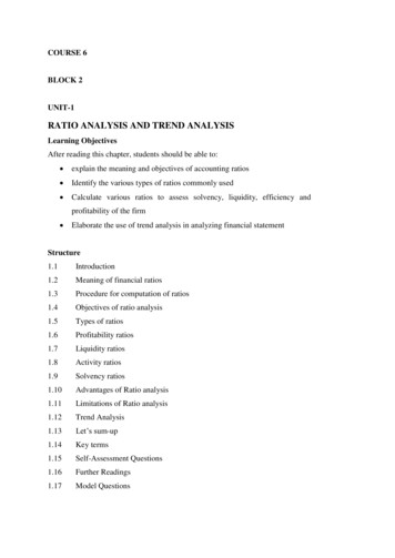
International Journal of Scientific & Engineering Research, Volume 7, Issue 3, March-2016ISSN 2229-5518141rotation rate of one or more rotor discs, therebysuccessful heavier-than-air vertical take off andchanginglandingits torque loadandthrust/liftcharacteristics.(VTOL) vehicles.However,earlyprototypes suffered from poor performance, andEarly in the history of flight, quadcopter (referredto as 'quadrotor') configurations were seen aspossible solutions to some of the persistentlatter prototypes required too much pilot workload, due to poor stability augmentation andlimited control authority.problems in vertical flight; torque-induced controlMore recently quadcopter designs have becomeissues (as well as efficiency issues originating frompopularthe tail rotor, which generates no useful lift) can beresearch. These vehicles use an electronic controleliminated by counter-rotation and the relativelysystem andshort blades are much easier to construct. Aaircraft.number of manned designs appeared in the 1920smaneuverability, these quadcopters can be flownand 1930s. These vehicles were among the firstindoors as well as outdoors.in unmannedaerialelectronic sensors toWiththeirsmallvehicle (UAV)stabilizesizeandtheagileIJSERFig 1.1 Quadcopter Structure CENTRAL HUBThe three major components of the alpieces of carbon fiber laminate milled tocomponentsthe desired specifications and shape.frameThese pieces serve to fasten the four armscumcrashof the quad-rotor together and hold theabsorber, and the arms. Initially vacuumelectronics hub off the ground. The carbonbag method may be used for makingfiber rods on the final design of the quad-carbon fiber laminates, and CNC millingrotor require two fasting points, where themachine may be used for the furthertest versionprecision fabricationrequired a single piece. The additionallandingtheThe center piece is created from two flat,centersupports,arerequired gearofthe quad-rotoronlyfastening point is due to the possibleweaknesses formed during the trickyIJSER 2016http://www.ijser.org
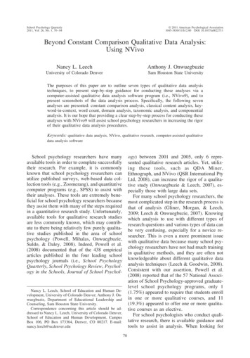
International Journal of Scientific & Engineering Research, Volume 7, Issue 3, March-2016ISSN ame’sversatilemany Place two thinner, one foot pieces of woodrunning nailed to the 2x4 length wise,andseparated by a distance slightly greatersimple, for easy adjustments, center piece.than the thickness of the rods.SPARS 142Machining the rectangular carbon fiber compressive enough to hold the rodrods has proven itself to be very difficult.firmly to the jig, adding support withoutPreliminary machining is done on testcrushing it.pieces to acclimate to the machine andmaterial. The best tool for cutting carbonFix the rod in place using tape. The tape is Drilling at high speeds, with a series of 3fiber rods is a diamond tipped jewelersbits each increasing in size proved asaw, however this tool is expensive andcapable method.unavailable.Consequently,othermanufacturing machines were used. The The carbon fiber splitting when using theIJSERband-saw catches the fibers rips the rod onthe blade causing it to splinter. There arealso problems drilling into carbon fiberrods. Since diamond tipped bits are alsounavailable, when the nondiamond drillbit is lowered to the face of the material,the fibers would snag on the bit and splitthe rods. These issues can be over come byfollowing a few steps:6 Degrees of Freedom ControlFig 1.2 6DOF control of quadcopterIJSER 2016http://www.ijser.orgband-saw can be overcome in a similarway as with drilling. Tape the rods in thesame way as done when drilling thecarbon fiber, however the tape should bethicker than before. The contraption is fedthrough the band-saw using a straight flatpiece of wood to brace the back of therods, preventing it from bending when theblade put pressure on it.
International Journal of Scientific & Engineering Research, Volume 7, Issue 3, March-2016ISSN 2229-5518143fibre. The fibre being aligned with thedirection of greatest stress.1.3 MATERIALS 1.3.1Carbon Fibre Carbon fiber reinforced plastic is over 4 timesCarbon fiber is composed of carbon atomsstiffer than Glass reinforced plastic, almost 20bonded together to form a long chain. Thetimes more than pine, 2.5 times greater thanfibers are extremely stiff, strong, and light,aluminium.and are used in many processes to create Carbon fibre is Electrically Conductiveexcellent building materials. Carbon fiber This feature can either be useful or be amaterial comes in a variety of "raw"nuisance. In Boat building conductivity has tobuilding-blocks,uni-be taken into account just as Aluminiumdirectional,weaves, braids, and severalconductivity comes into play. Carbon fiberothers, which are in turn used to createconductivity can facilitate Galvanic Corrosioncomposite parts.in fittings. Careful installation can reduce thisincluding yarns,IJSERproblem.1.3.2Properties of Carbon fibre Carbon fibre is very RigidCarbon fibre has High Strength to weightratioResistancetoFatigue in CarbonFiberComposites is good. Damage in tensileMaterials such as Aluminium, titanium,fatigue is seen as reduction in stiffness withmagnesium, Carbon and glass fiber, highstrengthFatigue Resistance is goodlarger numbers of stress cycles, (unless thesteel alloys all have good strengthtemperature is high)to weight ratios. Because of the way thecrystals of carbon fibre orient in long flatribbon or narrow sheets of honeycombcrystals, the strength is higher runninglengthwise than across the Fire Resistance/Non flammablecoated fiber is an example. Because carbonDepending upon the manufacturing processfiber is also chemically very inert, it can beand the precursor material, carbon fiber canused where there is fire combined withbe be made to feel quite soft to the handcorrosive agents. Carbon Fiber Blanket usedand can be made into or more often integratedas welding protection.into protective clothing for firefighting. Nickel IJSER 2016http://www.ijser.orgHigh Thermal Conductivity in some forms
International Journal of Scientific & Engineering Research, Volume 7, Issue 3, March-2016ISSN 2229-5518 Because there are many variations on theis a deterrent. Unless the weight advantage istheme of carbon fiber it is not possible toexceptionallypinpointaeronautics applications or racing, it often isexactlythethermallow thermal conductivity.further advantage.8 , dependingonthedirectionmeasured, the fabric weave, the precursormaterial, Pan based (high strength, higher cost.inmaintenance requirement of carbon fiber is atoextraashave been specifically designed for high or-1thesuchnotLow coefficient of thermal expansionworthimportant,conductivity. Special types of Carbon FiberCarbon fiber can have a broad range of CTE's, 144The low2. LITERATURE SURVEYDesign Of A Quadcopter Using PID ControlAlgorithmCTE) or Pitch based (high modulus/stiffness,D. Deva prakashlower CTE). Low Coefficient of ThermalThe military use of quadcopter has grown becauseexpansion makes carbon fiber suitable forof its ability to operate in dangerous locationsapplications where small movements can bewhile keeping human operators safe. Here, a low-critical. Telescopecost hover control mechanism is developed andIJSERandotheropticalmachinery is one such application.implemented on a microcontroller. Flight controlNonpoisonous, Biologically inert, X-Raybecomes simpler as the quadcopter hovers at apermeableconstant level from ground by itself, at the sameThese quality make Carbon fiber usefultime making it too easy to maneuver at heights andin Medicaluse,perform tasks such as imaging. A PID controlimplants and tendon repair, x-ray accessoriesmethod to obtain stability in flying the quadcoptersurgical instruments, are all in development.is designed. The model has four input forces whichAlthough not poisonous, the carbon fibers canare basically the thrust provided by each propellerbe quite irritating and long term unprotectedconnected to each rotor with fixed angle. Byexposure needs to be limited. The matrixvarying the speed of rear and front motors, we caneither epoxy or polyester, can however beobtain the pitch, roll and yaw motions of thetoxic and proper care needs to be exercised.quadcopter. Future improvements can be made toCarbon fibre is Relatively Expensiveimprove the design, to prove that it is possible toAlthough it offers exceptional advantages ofproduce a small scale UAV that can performStrength, Rigidity and Weight reduction, costfunctions of interest to the military as well asapplications.Prosthesiscommercial and industrial applications.IJSER 2016http://www.ijser.org
International Journal of Scientific & Engineering Research, Volume 7, Issue 3, March-2016ISSN 2229-5518Simple GUI Wireless Controller of , and control system design andD. HanafiThedesign,145implementation. The class has the objectives whichdevelopmentofremotelyoperatedare very clear for the students, and gainingQuadcopter system. The Quadcopter is controlledpractical skills in such a blend of several unrelatedthrough a graphical user interface (GUI) where thetechnical fields at the same time can give thecommunication between GUI and Quadcopter isstudents unique experience of system design andconstructed by using wireless communicationintegration, which can prove to be very useful insystem. The Quadcopter balancing condition istheir future career.sensed by FY90 controller and IMU 5DOF sensor.For smooth landing, Quadcopter is equipped withController Design for Quadcopter Using Labviewultrasonic sensor. All signals from sensors areThis paper describes the modelling of a four rotorprocessed by Arduino Uno microcontroller boardvertical take off and landing (VTOL) unmanned airand output from the Arduino Uno microcontrollervehicle known as Quadcopter air craft,which is aboard is implemented to control Quadcopternew model design method for the flight control ofpropellers. The GUI is designed using Visual Basican autonomous Quadcopter.The aim is to develop2008communicationa model of the vehicle as realistic as possible.Thebetween the Proportional, Integral and Derivativemodel is used to design a stable and accurate(PID) controller and the Quadcopter system. Thecontroller to develop a Image controlling methodexperiment shows that the Quadcopter system canusing LabView to obtain stability in flying thehover while maintain it balancing and the stabilityQuadcopter flying object.ExpressIJSERasinterfacingis guaranteed. Moreover, the developed system isable to cope with load disturbance up toConvertawings Model A QuadrotorMaximumThis unique helicopter was intended to be theoperated time of Quadcopter is six minutes usingprototype for a line of much larger civil and2200 mAh Lipo battery and operate time can bemilitary quadrotor helicopters. The design featuredincreased by using largest battery capacity.two engines driving four rotors through a system250 gduringthehoverposition.of v belts. No tailrotor was needed and control wasQuadcopter Design and ors. Flown successfully many times in the mid-Goponov. IThe design and implementation of quadrotorhelicopter system. The class is intended to providethe students with both theoretical and practicalknowledge in the areas of mechanical engineering1950s, this helicopter proved the quadrotor designand it was also the first four-rotor helicopter todemonstrate successful forward flight. Due to alack of orders for commercial or military versionsIJSER 2016http://www.ijser.org
International Journal of Scientific & Engineering Research, Volume 7, Issue 3, March-2016ISSN 2229-5518however,theprojectwasterminated.146to 173 mph (278 km/h).The Hanson ElasticConvertawings proposed a Model E that wouldArticulated (EA) bearingless rotor grew out ofhave a maximum weight of 42,000 lb (19 t) with awork done in the early 1960s at Lockheedpayload of 10,900 lb (4.9 t) over 300 miles and at upCalifornia by Thomas F. Hanson.3. DESIGN OF QUADCOPTERsolution toshape design,styling,surfacingworkflow and visualization to create, modify, and3.1 Design of QuadcoptervalidateThe design of quadcopter has been done by usingCATIA V5 software. The design is done in such away that there should not be any damage to thecomplexinnovativeshapesfromindustrial design to Class-A surfacing with theICEM surfacing technologies. CATIA supportsmultiple stages of product design whether startedpropellers, motors and electrical equipments.from scratch or from 2D sketches. CATIA is able toThe central hub, spars and the arms are designedread and produce STEP format files for reverseindividually and assembled.engineering and surface reuse.CATIAIJSERLength of the arm 215mmCATIA V5(ComputerAidedThree-DimensionalInteractive Application) started as an rer Avions Marcel Dassault, at that timecustomerofthe CAD/CAM CAD software[1] toLength of vertical and horizontal sides of centerbase 50mmLength of diagonal side of center base 67mmLength and breadth of rectangle drill 20*6mmdevelop Dassault's Mirage fighter jet. It was , and other industries.CATIA enables the creation of 3D parts, from 3Dsketches, sheetmetal, composites, molded, forgedor tooling parts up to the definition of mechanicalassemblies.The software provides advancedtechnologies for mechanical surfacing & BIW. Itprovides tools to complete product definition,includingfunctionaltolerancesaswellas kinematics definition. CATIA provides a widerange of applications for tooling design, for bothgeneric tooling and mold & die. CATIA offers aIJSER 2016http://www.ijser.org
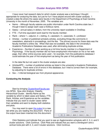
International Journal of Scientific & Engineering Research, Volume 7, Issue 3, March-2016ISSN 2229-5518147Fig 3.2 central hubFig 3.1 2D structural parts of quadcopterIJSER3D Design of the Quadcopter partsFig 3.4 ArmFig 3.3 3D central hubIJSER 2016http://www.ijser.org
International Journal of Scientific & Engineering Research, Volume 7, Issue 3, March-2016ISSN 2229-5518148Assembly of the Arm and Central hubIJSERFig 3.5 complete assembly of the ArmThe 2D view of the arm is ddrawn in the catia v5another plane on the side wich we need to add thesoftware and it is converted in to 3d view byfuther design. After sketching that part on thegiving thickness of 20mm. like wise the arm standplane and it is converted in to 3D by using 3D tooland the knife edge curvature is designed andbar. The holes are drilled by using drill bit in theconverted it in to 3D view. The three parts can betool bar. Same as the arm stand the knife edge ofdesigned individually or at a time by creatingthe arm is created and converted in to 3D.IJSER 2016http://www.ijser.org
International Journal of Scientific & Engineering Research, Volume 7, Issue 3, March-2016ISSN 2229-5518149IJSERFig 3.6 assembly of central hub and armThe figure shows the top view of the assembly ofand the knife edge. The central rectangle holes arethe central hub and the arm. The both parts aredrilled of light 20mm and thickness 20mm. The flatsketched and designed individually. So by usingbouncer edge of the arm is also of 20mm so that thecatia vs or ProE softwares the assembly ca be done.edge of the arm will be clamped correctly in theThe figure is assembled with our the arm standcentral4. ANALYSIS4.1 Analysis of Quadcopter designAnalsysis of thr parts of the designed quadcopteris done by using ANSYSsoftware. Ansys softwareis the tool of the FEM analysis. Here we are goingto make the analysis of the material by usingcarbon fibre. The parts ae meshed first and thenIJSER 2016http://www.ijser.orghub.
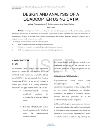
International Journal of Scientific & Engineering Research, Volume 7, Issue 3, March-2016ISSN 2229-5518150analysed with the specific boundary conditionsof engineering disciplines,ande.g., electromagnetism, heattransfer,variousloads.and fluiddynamics.A variety of specializations under the umbrella ofthe mechanical engineering discipline (such es) commonly use integrated FEM indesign and development of their products. SeveralmodernFEMpackagesincludespecificcomponents such as thermal, electromagnetic,fluid, and structural working environments. In aFig 4.1 Forces based on motor basisstructural simulation, FEM helps tremendously in4.2 FEM ANALYSISproducing stiffness and strength visualizations andIJSERThe finite element method obtained its realalso in minimizing weight, materials, and costs.impetus in the 1960s and 1970s. The methodFEM allows detailed visualization of whereoriginatedstructures bend or twist, and indicates thefromtheneedtosolvecomplex elasticity and structural analysis problemsdistribution of stresses and displacements.incivil and aeronautical engineering.The methodFull assembly of one arm, after meshing, applyinghas since been generalized for the numericalboundary conditions. One end is fixed and motormodeling of physical systems in a wide varietybase is applied with 10 N of load.Maximum stress - 2.09mpaMinimum stress- 2.25 e-005 paIJSER 2016http://www.ijser.org
International Journal of Scientific & Engineering Research, Volume 7, Issue 3, March-2016ISSN 2229-5518Fig 4.3 Displacement of Arm under applied loadDisplacement vector – 0.0235mmIJSERFig 4.4 Force on horizontal planeForce applied – 10Fig 4.5 Force on landing gearForce applied – 10NIJSER 2016http://www.ijser.org151
International Journal of Scientific & Engineering Research, Volume 7, Issue 3, March-2016ISSN 2229-5518152Fig 4.6 force based on motor basis5. FABRICATION AND ASSEMBLYThe binding polymer is often a thermoset resin5.1 Carbon fibre manufacturingsuchbutotherthermosetIJSERCarbon fiber–reinforced polymer, carbon fiber–reinforcedas epoxy,plastic or carbonfiber–reinforcedthermoplastic (CFRP, CRP, CFRTP or often simplycarbon fiber, or even carbon), is an extremelystrong and light fiber-reinforced polymer whichcontains carbon fibers.or thermoplastic polymers, such as polyester, vinylester or nylon, are sometimes used. The compositemay contain other fibers, Such as aramid e.g.Kevlar, Twaron, aluminium, Ultra-high-molecularweight polyethylene(UHMWPE) or glass fibers, aswell as carbon fiber. The properties of the finalCFRP product can also be affected by the type ofCFRP’s can be expensive to produce but areadditives introduced to the binding matrix (thecommonly used wherever high strength to weightresin). The most frequent additive is silica, butratio andsuchother additives such as rubber and carbonas aerospace, automotive and civil engineering, spnanotubes can be used. The material is alsoortsreferred to as graphite-reinforced polymer orrigiditygoods andanarerequired,increasingnumberother consumer and technical applications.ofgraphite fiber-reinforced polymer (GFRP is lesscommon, as it clashes with glass.IJSER 2016http://www.ijser.org
International Journal of Scientific & Engineering Research, Volume 7, Issue 3, March-2016ISSN 2229-5518153Computer numerical control (CNC) is a specializedCompression moldingA quicker method uses a compression mold. Thisis a two-piece (male and female) mold usuallymade out of aluminum or steel that is pressedtogether with the fabric and resin between the two.The benefit is the speed of the entire process.However, this technique has a very high initial costsince the molds require CNC machining of veryhigh precision.The above figure shows the carbon fibre afterand versatile form of soft automation and itsapplication cover many kinds, although it wasinitially developed to control the motion andoperation of the machine tools.Machining processThe sketches are machined with carbon fibre byusing CNC machine with the help of Artcam Prosoftwarecompleting the compression moulding process.Artcam Pro: A complete solution for the designThe process took two days to complete.and manufacture of 2D Artwork & 3D Reliefs. This5.2 Design Fabrication using CNC machining.was the software used to give sketch commandsIJSERandcodesFig 5.6 cutting of carbon fibre using CNCIJSER 2016http://www.ijser.orgtotheCNCmachine
International Journal of Scientific & Engineering Research, Volume 7, Issue 3, March-2016ISSN 2229-55181545.4 DC Motorsprogramming interface ensures future softwareFour brushless DC motors and propellers has beenused.updates will be quick and easy.5.6 TransmitterSpecificationsHere we use avionic RCB6i transmitter withreceiver. This is one of the advanced transmitterwith receiver to control the quadcopters and miniuav’s.Diameter – 27.9mmLength -39.7mmWeight -53gKV – 935Maximum thrust - 860G5.7 Lipo battery5.5 Flight Control BoardHere KK 2.1.5 flight controlboard is used. Theoriginal KK gyro system has been updated to theA lithium polymer battery, or more correctlylithium-ion polymer battery (abbreviated variouslyas LiPo, LIP, Li-poly and others), is a rechargeablebattery of lithium-ion technology in a pouchformat.IJSERincredibly sensitive 6050 MPU system making thisthe most stable KK board ever and adds the5.8 ESC (Electronic speed control)addition of an auto-level function. At the heart ofAn electronic speed control or ESC is an electronicthe KK2.1 is the ATMEL Mega 644PA 8-bit AVRcircuit with the purpose to vary an electric motor'sRISC-based microcontroller with 64k of memory.speed, its direction and possibly also to act asAn additional header has been added for voltagea dynamicdetection, so now there is no need for on-boardelectrically powered radio controlled models, withsoldering. A handy piezo buzzer is also includedthewith the board for audio warning when activatingmotors essentiallyand deactivating the board,which can begenerated three-phase electric power low voltagesupplemented with an LED for visual signaling. Asource of energy for the motor. An ESC can be ahost of multi-rotor craft types are pre-installed,stand-alone unit which plugs into the receiver'ssimply select your craft type, check motorthrottle control channel or incorporated into thelayout/propeller direction, calibrate your ESCs andreceiver itself, as is the case in most toy-grade R/Cradio and you’re ready to go! All of which is donevehicles. Some R/C manufacturers that installwith easy to follow on screen prompts! If you’reproprietary hobby-grade electronics in their entry-new to multi-rotor flight or have been unsurelevel vehicles, vessels or aircraft use onboardabout how to setup a KK board then the KK2.1 waselectronics that combine the two on a singlecircuitbuiltboard. Here for this quadcopter 20amps esc hasforyou.The6PinUSBaspAVRvarietybeen used.IJSER idingoftenusedonusedfor brushlessanelectronically
International Journal of Scientific & Engineering Research, Volume 7, Issue 3, March-2016ISSN 2229-55181555.9 Fabricated modelIJSER There is no effet to the rotors bilityUAV(Quadcopter) design is fabricated usingcarbon fibre of crash resistability and made it tofly successfully.and othr electrical components by usingthis design. The strength and resistance capacity isincreased. FUTURE WORKThis Structural Analysis of the carbon fibre leadsto the following conclusions:- Advanced techonology can be used likeautopilot system etc. Vibration got reduced when compared tothe plastic uav. By using sensors and cameras can be usedfor defence and airforces. Still more miniature uav can be made byusing this design.IJSER 2016http://www.ijser.org
International Journal of Scientific & Engineering Research, Volume 7, Issue 3, March-2016ISSN 2229-5518REFERENCES D. Deva Prakash and P. Anantha christu RajDesign Of A Quadcopter Using PID ControlAlgorithm, , vol-1 , 2014. D. Hanafi, M. Qetkeaw, R. Ghazali, M. Than,W. Utomo and R. Omar, "Simple GUIWirelessControllerofQuadcopter," temSciences, Vol. 6 No. 1, 2013. K. W. Weng, “Quadcopter,” Robot Head toToe Magazine, Vol. 10, 2011. QuadcopterdesignandImplementation,Gaponov. I, TALE, IEEE Intrnationalconference, 2012.IJSER L. Salih, M. Moghavvemil, H. A. F.Mohamed and K. S. Gaeid,“Flight PidController Design For A UavQuadcopter,”Scientific Research and Essays, vol 5(23),pp.3660-3667,December 2010.IJSER 2016http://www.ijser.org156
a. Study the static and dynamic parameters of the framework b. Workout the parameters by analysis, design, and optimization of structure. c. Study of existing quadcopters and the parameters affecting its performance. 1. INTRODUCTION. 1.1 UAV . An. unmanned aerial vehicle (UAV), commonly known as a drone ground.and also referred to as an