Transcription
—Wireless ControllerARC600Product Guide
Wireless ControllerARC600Product version: 3.4.71MRS758465 GContents1. Description. 39. Mounting. 202. Complete communication system.410. Ordering data. 203. Application. 511. Accessories and ordering data. 204. Battery condition monitoring.912. Tools. 205. Motor overload protection. 913. Terminal diagrams.216. Physical interfaces.1014. References.227. Communication. 1415. Document revision history. 238. Technical data. 15DisclaimerThe information in this document is subject to change without notice and should not be construed as a commitment by ABB. ABB assumes no responsibility for anyerrors that may appear in this document. In case of discrepancies between the English and any other language version, the wording of the English version shallprevail. Copyright 2021 ABB.All rights reserved.TrademarksABB is a registered trademark of the ABB Group. All other brand or product names mentioned in this document may be trademarks or registered trademarks of theirrespective holders.2ABB
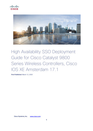
Wireless ControllerARC600Product version: 3.4.71. DescriptionWireless Controller ARC600 is a compact, solution baseddevice for remote controlling and monitoring of secondarysubstations, such as network disconnectors, load breakswitches and ring main units (RMU) in distribution networks. Itenables the SCADA system to wirelessly monitor and controlthe field devices over the public communication infrastructure(cellular network). Wireless Controller ARC600 utilizes thebuilt-in wireless communication features for reliable andsecure end-to-end communication providing remotemonitoring and control of three switching devices and can beexpanded as required by using external I/O expansionmodules.The use of Wireless Controller ARC600 in distributionnetworks improves the quality of power distribution andreduces the outage time in the affected areas. Areas directlyadjacent to these affected areas show reduced outages and1MRS758465 GIssued: 2021-05-31Revision: Goverall effects. This also reduces the capital expenditures inthe distribution network by allowing integration of legacydevices and contributes to more direct cost savings byfacilitating preventative maintenance. The operationalexpenditure can be reduced by lowering the System AverageInterruption Duration Index (SAIDI) and System AverageInterruption Frequency Index (SAIFI), resulting in lowerpenalties for undelivered energy. Wireless Controller ARC600is also ideally suited to be retrofitted to existing applicationsthus enabling the remote control of these devices and furtherextending the life cycle of the switching devices itself.Typically, the IEC-104 protocol is utilized for communicationto the SCADA system but for the existing installations with aIEC-101 line or modem, Wireless Controller ARC600 supportsalso IEC-101 communication (including dial-up) to the 244 V1 EN-USFigure 1.ABBCommunication system overview with Wireless Controller ARC600 and ring main unit3
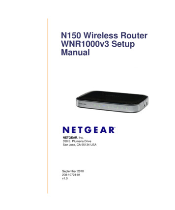
Wireless ControllerARC600Product version: 3.4.71MRS758465 GGUID-3496BF1A-45BE-43DD-A903-C43E36EF172D V1 EN-USFigure 2.Wireless Controller ARC600 at remote site connected with ring main unit and RIO600. RTU monitoring and control combined withdirectional fault passage indication example.2. Complete communication systemWireless Controller ARC600 is typically part of a completecommunication system which consists of Arctic 600 seriesgateways or controllers and a central M2M Gateway ARM600communication server. The M2M gateway is an essential partof the total communication solution and offers features thatare needed to build a reliable end-to-end communicationsystem.4 Static IP addressing for Arctic 600 series devices –Possibility to use operator independent standard SIMcards VPN Concentrator – Secure communication between acentral location and remote sites Arctic Patrol – Centralized device managementapplication for the Arctic 600 series devices monitoringand controlling Firewall – A network security system to control theincoming and outgoing network trafficABB
Wireless ControllerARC600Product version: 3.4.73. ApplicationThe functionalities of Wireless Controller ARC600 have beendeveloped to monitor and control switching devices inside asecondary substation. Connected to the central controlsystem (SCADA/DMS) that manages the utility network, theyserve as the core of the secondary substation automationsystem.Key features Highly reliable control and monitoring of up to threeswitching devices per ARC600– Status information of three switching devices andthree earthing disconnectors– Disconnector position and earthing status indicationswith front LEDs– Local and remote use of the disconnectors Overload protection of actuator motors– Load current measured in the motor circuit– Current limit based motor overload protection(software fuse)– Measurement of disconnector open and close times Fault Passage Indication (FPI) support for improved faultmanagement– Support for external medium voltage directional faultindication and for multifunction low voltage powerquality metering Integrated wireless communication– Always on two-way communication based on cellularnetworks (GPRS, 3G, LTE)– Communication monitoring and automatic connectionre-establishment– High level data security through internal VPN andFirewall– Support for Arctic Patrol centralized devicemanagement applicationABB1MRS758465 G Protocol converter– Conventional IEC-101 and Modbus serial devices canbe connected in a reliable way to the modern TCP/IPbased IEC-104 and Modbus TCP control systems Built-in battery charger with advanced battery control– Temperature compensated charging– Battery monitoring/testing (condition monitoring)– Deep discharge protection IEC-101 SCADA compliancy– IEC 60870-5-101 slave (including dial-up) to supportthe existing system installations– Possibility for future SCADA migration from IEC-101 toIEC-104 is supported as the operating mode isselected using the parameter settings– IEC-101 operation mode as unbalanced slave Heater control to limit the effects of ambient temperaturevariations such as condensation Robust aluminium casing design and easy DIN railmounting5
Wireless ControllerARC600Product version: 3.4.71MRS758465 GDistributionsubstationPower generationReclosersVPNGPRS/3G/LTECellular networkInternetVPNARM600Control roomSCADA / 4974-A662-C50D01401F02 V1 EN-USFigure 3.6Communication solution in distribution automation overviewABB
Wireless ControllerARC600Product version: 3.4.71MRS758465 GApplication examplesMVARC600ACMRemoteauxonoffBattery charging 24V DC mA-OBattery testRelayHeater controlIOIHallsensorUEMC 50GUID-2EA84B83-9D8A-4B3F-AC97-D99930FCB53B V4 EN-USFigure 4.ABBWithin the UEMC 50 the ARC600 unit is used for the remote control of a disconnector. The motor operating device is placed in thesame UEMC 50 enclosure as the other equipment.7
Wireless ControllerARC600Product version: 3.4.71MRS758465 GSF6 AlarmARC60090.264V ACor 85.200V DCauxMBattery charging 24V DCMRemoteonoff mA-Battery testHeater controlRelayOIOII OFIIOIHallsensorSerial portMVLV compartment in F30B V5 EN-USFigure 5.8An ARC600 unit used for the remote control of a Ring Main Unit and fault indicationABB
Wireless ControllerARC600Product version: 3.4.71MRS758465 GMVMARC600ACauxBattery charging 24V DCRemoteonoff mA-OBattery testRelayIHeater controlOIHallsensorUEMC Control CabinetGUID-D6E454C7-00B1-4D98-8EFE-62048B5E37D4 V4 EN-USFigure 6.Within the UEMC control cabinet, the ARC600 unit is used for the remote control of a disconnector. The motor operating device isfitted to the disconnector.4. Battery condition monitoringWireless Controller ARC600 is equipped with a conditionmonitoring based battery charger. This allows scheduledmonitoring of the backup batteries inside the control cabinetwhich enables the optimization of lifetime and maintenanceintervals of the backup batteries. The backup battery can beeither manually or periodically tested by switching off thecharger and switching on the external dummy load.Manual testing can be initiated from a central control systemvia the IEC-104 protocol. Based on the current and voltagemeasurements taken from the battery, an assessment ismade regarding the battery’s condition and remainingoperational capacity (in Ah). Based on these measurements ofthe battery’s current and voltage levels, an IEC 60870-5-104alarm event is then generated in the system.ABBARC600 has also protection against complete batterydischarge.5. Motor overload protectionWireless Controller ARC600 protects the disconnector motorby using overcurrent detection. The current of thedisconnector motor is continuously measured and if thepreset value is exceeded, the current supply to the motor iscut. The preset current value should be set so that thecurrent supply to the motor is cut before the motor protectionfuse opens the circuit. This leads to less site visits to resetthe fuse. Typically, rust or ice might cause the disconnectorblades to get stuck in the closed position, resulting in eitherdamage to the disconnector motor due to overcurrent oroperation of the protection fuse.9
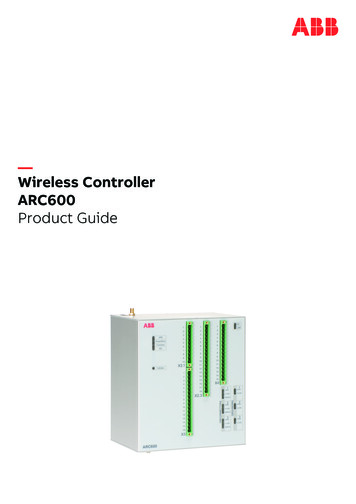
Wireless ControllerARC600Product version: 3.4.71MRS758465 G6. Physical interfacesWireless Controller ARC600 is equipped with numerousinputs and outputs to interface with the controllablesubstation equipment. ARC600 has 17 binary inputs, 10binary outputs and 2 analog inputs. There are also two serialports (RS-232, RS-485) and one LAN/WAN port for deviceconnectivity.12632Front panel LEDsARC600 is equipped with groups of LEDs indicating thecomplete operational status of the device. The LEDs arelocated on the front panel and are identified by theaccompanying 712F V3 EN-USFigure 7.Front panel1 System status LEDs2 X2.1 connector3 X2.3 connector4 X4 connector5 AC and LINK LEDs6 X3 connector7 Disconnector status LEDs8 Grounding disconnector status LEDs10ABB
Wireless ControllerARC600Product version: 3.4.71MRS758465 GTable 1. Description of available LEDsLabelStateDescriptionVPNOnVPN connection is upFlashingVPN connection is startingOffVPN connection is disabledOnOperating power is turned onOffOperating power is turned offOnDevice is startingFlashingDevice is operating normallyOnEthernet link is upFlashingEthernet link is transferring dataOffEthernet link is downFlashingCellular connection is starting or transferring dataOffCellular connection is inactiveOnConnected to AC powerOffNot connected to AC powerOnIEC 60870-5-104 control link to SCADA is activeOffIEC 60870-5-104 control link to SCADA is activeOn/OffOpen position indication for SCONNECTORS 1.3OPENCLOSEREMOTEGROUNDING 1.3OPENCLOSEABBClose position indication for disconnectorOnRemote control indicationOffLocal control indicationOn/OffOpen position indication for grounding disconnectorClose position indication for grounding disconnector11
Wireless ControllerARC600Product version: 3.4.71MRS758465 GSerial 41 V3 EN-USFigure 8.Serial panel1 Console serial port (DIP switch selectable application or console port RS1)2 Power switch3 Serial console switch (RS1)4 Serial port 2 hardware configuration DIP switches5 Serial port 26 Ethernet connectorAntenna panelARC600 has a SIM card insertion slot with SIM card tray andSMA type antenna connector on the antenna panel.12ABB
Wireless ControllerARC600Product version: 3.4.71MRS758465 G123GUID-35D4C58E-AD09-401B-91D1-09917E75F5C2 V2 EN-USFigure 9.Antenna panel1 SIM card tray connector2 SIM card tray release button3 Antenna connector SMA (female)ABB13
Wireless ControllerARC600Product version: 3.4.77. CommunicationWireless Controller ARC600 provides a complete solution formonitoring and controlling field devices. A securecommunication channel can be formed for remote serial(RS-232/RS-485) or Ethernet field devices over a GPRS, 3Gor LTE connection. ARC600 makes it possible to have costeffective communication networks over long distances at highdata rates.Several interfaces are available for field device connectivity:digital inputs and outputs, analog inputs, serial and Ethernetports. Industrial protocols IEC-104, IEC-101 and ModbusTCP are supported for the SCADA connectivity. The inputsand outputs of ARC600 can be accessed and controlled withthe IEC-104 and IEC-101 protocols.With the Wireless Controller ARC600 protocol conversionfeature, conventional IEC-101, Modbus RTU and ModbusTCP devices can be connected in a reliable way to modernTCP/IP based IEC-104 control systems.Modbus to IEC-104 conversionARC600 provides support for generic Modbus RTU andModbus TCP devices such as ABB's RIO600. In addition,support is also provided for the preselected Modbusparameters for Fault Passage Indicators (FPI). Currently,Horstmann Compass B and Kries IKI-50 are supported.ARC600 polls the fault indicator devices, connected to theserial port, using Modbus protocol and converts the values toIEC 60870-5-104. Up to four fault indicators can beconnected to one device. IEC 60870-5-104 is used tocommunicate towards a SCADA via the Arctic M2M Gatewayover the available customer chosen cellular data network.IEC-101 to IEC-104 conversionWith ARC600, conventional IEC 60870-101 serial devices canbe attached to a modern TCP/IP based IEC 60870-5-104141MRS758465 Gcontrol system. This is enabled by the protocol conversionfrom IEC 60870-5-101 to IEC 60870-104. In this case,ARC600 (IEC-101 master) uses local synchronous datapolling where it continuously sends requests and the IEC-101device (IEC-101 slave) responds. In the direction of thecontrol room, the communication protocol is IEC-104 andARC600 can send events asynchronously as they arise whileSCADA performs only slow-period background scans.Another advantage of the local protocol conversion is anadvanced data acknowledgement mechanism. IEC-104allows multiple packets, and multiple events in a singlepacket, to be acknowledged collectively and the packets canbe buffered up to the time of acknowledgement from SCADA.Modbus RTU to Modbus conversionModbus field devices use usually serial mode (RTU or ASCII)protocol while the SCADA communication uses TCP/IP basedModbus TCP protocol. The Modbus user community hasdefined the functionality for required protocol integration, thatis, how the Modbus RTU devices can talk to the Modbus TCPSCADA system. This functionality is a protocol conversionand it is implemented in ARC600. Many industrial devices likePLCs and RTUs support RS-485 Modbus RTU mode. InRS-485 mode, ARC600 can integrate unlimited number ofserial slaves to TCP/IP network (SCADA).ARC600 has two application serial ports. Serial port 1 isconfigurable to either console or data mode and it supportsonly RS-232, while serial port 2 is configurable to multipleserial modes (RS-232/RS-422/RS-485). Serial portconnectors are 9-pin D-sub (male) connectors. Moreinformation is available in the Technical data section of thisproduct guide or technical manual available atabb.com/substationautomation.ABB
Wireless ControllerARC600Product version: 3.4.71MRS758465 G8. Technical dataTable 2. DimensionsDescriptionValueHeight Width Depth175 160 108 mmWeight2.4 kgProtection classIP30Table 3. HardwareDescriptionProcessor environmentValueProcessor32 bit RISCMemory128 MB Flash128 MB RAMOtherPowerSensorTemperatureInternal clockReal timePower supply90.264 V AC or 85.200 V DC20.30 V DC (external battery)Frequency range45.65 HzInput current, 100% load, 230 VAC0.8 AEfficiency, typical (230 V AC,100% load) 83%IsolationInput/ground 1500 V AC RMS 50 Hz 1 min InputOutput 3000 V AC RMS 50 Hz 1 minOutput/ground 500 V DCInrush current 25 C, 230 V AC 25 A 5 msInput fuseT3.15 A high breakingPower consumption10 W typical (when not charging battery), 60 W (full charging)Overvoltage transient protectionVDR 275 V AC 72 JHoldup time (230 V, 100% load) 50 msCasingAluminium shellApprovalsCEEnvironmental conditionsTemperature range-30. 55 C (non condensing)-40. 70 C (storage)Relative humidity5.85% RHTable 4. Battery recommendationsDescriptionYasa NP 17-12Yasa NPL 24-12Rated voltage12 V12 VCapacity17 Ah24 AhWeight6.1 kg9 kgSize (L W H)181 76 167 mm166 175 125 mmABB15
Wireless ControllerARC600Product version: 3.4.71MRS758465 GTable 5. Supply for external devices and input circuits (X2.1 pin 6)DescriptionValueOutput voltage21.29 VOutput current1 A continuous, 3 A peakOutput overvoltage protection level30.5 VTable 6. Temperature-compensated charger for batteriesDescriptionValueRated charging voltage27.4 V at 20 COutput power60 WFuse4ATemperature compensation-40 mV/ COutput overvoltage protection level30.5 VTable 7. Supported protocolsMaster protocolSlave protocolIEC 60870-5-104IEC 60870-5-101IEC 60870-5-104Modbus TCPIEC 60870-5-104Modbus RTU/ASCIIIEC 60870-5-104Modbus (RTU) profile for Horstmann Compass BIEC 60870-5-104Modbus (RTU) profile for Kries IKI-50IEC 60870-5-101Modbus RTUIEC 60870-5-101Modbus TCPIEC 60870-5-101Modbus (RTU) profile for Horstmann Compass BIEC 60870-5-101Modbus (RTU) profile for Kries IKI-50Modbus TCPModbus RTUTCP/IPSerial gateway - serial port data stream (such as DNP3)Table 8. Supported protocols for I/O controllingMaster protocolIEC 60870-5-104IEC 60870-5-10116ABB
Wireless ControllerARC600Product version: 3.4.71MRS758465 GTable 9. Default I/O configurationDescriptionValueDigital inputs (0.60 V DC, 18 V DC detectedas 1)Digital outputs (1 A/30 V DC continuous carry)Analog inputs (-5. 5 V measurement, 300mV for -10. 55 C, 0 V. 5 V)Digital inputs for the disconnector statuscontrol Disconnector 1: Open/closed, local/remoteuse, grounding open/closed – 5 pcs Disconnector 2: Open/closed, local/remoteuse, grounding open/closed – 5 pcs Disconnector 3: Open/closed, local/remoteuse, grounding open/closed – 5 pcs15Extra general purpose digital inputs reservedfor other use2Total number of digital inputs17Digital outputs for the disconnector open/closecommand Disconnector 1: Open/close – 2 pcs Disconnector 2: Open/close – 2 pcs Disconnector 3: Open/close – 2 pcs6Digital output for the load cut (motor overloadprotection)1Digital output for the test load of the batterytest (test load)1Digital output for the external heater1Extra general purpose digital output reservedfor other use1Total number of digital outputs10Load measurement (DC motor load current)1Extra reserved for other use1Total number of analog inputs2Table 10. I/O specificationsDescriptionDigital inputsDigital outputsABBValueNumber of digital inputs17Operating range18.60 V DC ( 18 V DC detected as 1)Current drain3.5.12.5 mAPower consumption/input 0.8 WInput polaritybipolarIsolation3 kVNumber of digital outputs10Output pin rated voltage24 VDCContinuous carry 30 VDC1A17
Wireless ControllerARC600Product version: 3.4.71MRS758465 GTable 11. Network interfacesDescriptionEthernet portsValueEthernet/LAN10/100 Base-T. Shielded RJ-451.5 kV isolation transformerEthernet IEEE 802-3, 802-2Serial portsSerial 1/ConsoleRS-232 DTEMale DB-9 connectorIEC 60870-5-101 protocol supportFull serial and modem signals300.460 800 bpsData bits: 7 or 8Stop bits: 1 or 2Parity: None, Even, OddFlow control: None, RTS/CTSProtection: 15 kV ESD and short circuitConsole: RS-232, 19200 bps, 8 data bits, 1 stop bit, no parity (8N1)Serial 2RS-232 DTE, RS-422, RS-485 (selectable)Male DB-9 connectorIEC 60870-5-101 protocol supportFull serial and modem signals300.460 800 bpsData bits: 7 or 8Stop bits: 1 or 2Parity: None, Even, OddFlow control: None, RTS/CTSProtection: 15 kV ESD and short circuitTable 12. Electromagnetic compatibility testsDescriptionReferenceEmission tests according to thetest specification IEC 61850-3(Edition 2.0 2013-12)Radiated disturbanceCISPR 16-2-3Conducted disturbanceCISPR 16-2-1Immunity tests according to thetest specification IEC 61850-3(Edition 2.0 2013-12)Electrostatic discharge (ESD)EN 61000-4-2 (2008-12)Radiated radiofrequencyelectromagnetic fieldEN 61000-4-3 (2006-02)Electrical fast transient (EFT)EN 61000-4-4 (2012-04)SurgeEN 61000-4-5 (2005-11)Conducted radiofrequencyelectromagnetic fieldEN 61000-4-6 (2008-10)Power frequency magnetic fieldEN 61000-4-8 (2009-09)Voltage dipsEN 61000-4-11 (2004-03)18ABB
Wireless ControllerARC600Product version: 3.4.71MRS758465 GTable 13. RoHS and REACH compliancyDescriptionReferenceDirectiveRoHS directive 2002/95/ECREACH directive 2006/1907/ECABB19
Wireless ControllerARC600Product version: 3.4.79. MountingThe devices have been equipped with mountingarrangements that are specially designed to enable DIN railmounting inside the control cabinets. A set of DIN railmounting clips is included with the devices.1MRS758465 GThe order number consists of a string of codes generatedfrom the device's hardware and software modules. Use ABBLibrary to access the selection and ordering information andto generate the order number.10. Ordering dataThe product label contains basic information about the unitsuch as product name, serial number and Ethernet MACaddress.The product label is found on top of the device.Table 14. Ordering dataDescriptionARC600A2324NARadio IFLTEData speed maxSee the mobile data reference guide (2NGA001029).11. Accessories and ordering dataCertain equipment accessories can be attached to thedevices to increase the flexibility and functionality of thedevices according to the application requirements within thenetwork. More information regarding these additions shouldbe requested and discussed when planning and ordering theequipment from ABB Distribution Automation. Replacementparts for the devices are also available from ABB. Thisincludes all external parts or components of the sold devicethat could have been damaged or lost. ABB does not supplyinternal components or parts. The external replacement parts,on the other hand, can be ordered from ABB After-SalesService via Parts-OnLine .Table 15. AccessoriesDescriptionOrder codeTest load resistor2RCA028171NTC resistor2RCA028226Hall sensor2RCA0282273G puck antenna (SMA male)2RCA037240DIN rail mounting kit (metal)2RCA037241I/O connector set2RCA037242Power cord (European plug)2RCA037647SMA(m)/FME(m) adapter1)2RCA037659Laird LTE antenna 700.2700 MHz (SMA male)2RCA0376601)Needed for single SIM Arctic products, if the third party antenna's connector type is FME femaleMore information is also available fromaftersales.relays@fi.abb.com.12. ToolsThe devices can be configured using a graphical userinterface via a Web based browser. A conventional console20interface is also provided. Software updates or configurationadjustments for the devices can be made remotely byuploads over the network from the central control center.ABB
Wireless ControllerARC600Product version: 3.4.71MRS758465 G13. Terminal diagramsAC STATUSSADCACSBSCRALNNTC APENTC 6EC3EF V1 EN-USFigure 10.X2.1 connector schematicsWith DC (85.200 V DC), connect thenegative wire to L and the positive to N.OPENED 1 CLOSED 1 OPENED 2 CLOSED 3 LOC/REM 1LOC/REM 2CLOSE 1OPEN 1CLOSE2OPEN 2GUID-1087841A-5BD0-4724-B006-C7D415167D17 V2 EN-USFigure 11.ABBX2.3 connector schematics21
Wireless ControllerARC600Product version: 3.4.71MRS758465 GDISCONNECTOR 3 STATUS & CONTROLOPENED 3 CLOSED 3LOC/REM 3GROUNDING DISCONNECTORS STATUSCLOSE 3OPEN 5-EE3284251506 V1 EN-USFigure 12.12LOAD/CUTX3 connector schematics34LOAD CURRENT56TEST LOAD78HEATER910-5.5 V1)13EXTRA INPUTS1415EXTRA OUTPUTGUID-4A4FF16A-8E32-41CD-989E-AC0900D9C845 V2 EN-USFigure 13.1)X4 connector schematicsCan be used as a 4.20 mA input using external resistor14. ReferencesThe abb.com/substationautomation portal providesinformation on the entire range of distribution automationproducts and services.22ABB
Wireless ControllerARC600Product version: 3.4.71MRS758465 G15. Document revision historyDocument revision/dateProduct versionHistoryA/2015-12-18AFirst releaseB/2017-06-073.3Content updatedC/2017-09-223.4Content updated to correspond to the product versionD/2019-04-243.4.7Content updated to correspond to the product versionE/2021-02-193.4.7Content updatedF/2021-02-253.4.7Content updatedG/2021-05-313.4.7Content updatedABB23
—ABB Distribution SolutionsDigital Substation ProductsP.O. Box 699FI-65101 VAASA, FinlandPhone 358 10 22 11 Copyright 2021 ABB. All rights reserved.1MRS758465 Gabb.com/mediumvoltage
IEC-101 line or modem, Wireless Controller ARC600 supports also IEC-101 communication (including dial-up) to the SCADA system. GUID-533791DB-D17E-49EA-B2AB-8E13618BF244 V1 EN-US. Figure 1. Communication system overview with Wireless Controller ARC600 and ring main unit. Wireless Controller 1MRS758465 G ARC600 Product version: 3.4.7 Issued: 2021 .