Transcription
HP Smart Array P400 ControllerUser GuideOctober 2005 (First Edition)Part Number 399716-001
Copyright 2005 Hewlett-Packard Development Company, L.P.The information contained herein is subject to change without notice. The only warranties for HP products and services are set forth in the expresswarranty statements accompanying such products and services. Nothing herein should be construed as constituting an additional warranty. HPshall not be liable for technical or editorial errors or omissions contained herein.October 2005 (First Edition)Part Number 399716-001Audience assumptionsThis document is for the person who installs, administers, and troubleshoots servers and storage systems.HP assumes you are qualified in the servicing of computer equipment and trained in recognizing hazardsin products with hazardous energy levels.
ContentsHardware features . 5Board components . 5SAS/SATA connectors on the front of the board . 5SAS/SATA connectors on the back of the board. 6Controller specifications . 6Overview of the installation procedure . 8Installing the controller in an unconfigured server . 8Installing the controller in a previously configured server . 8Installing the controller hardware . 10Before beginning the installation . 10Preparing the server. 10Installing the controller board. 10Connecting storage devices . 11Updating the firmware . 12Methods for updating the firmware . 12Configuring an array . 13Introduction . 13Comparing the utilities . 13Using ORCA. 14Using ACU . 15Using CPQONLIN. 15Setting drive rebuild, expand priority, and accelerator ratio. 15Expanding an array. 16Adding or configuring spare drives. 16Migrating RAID level and stripe size online . 17Setting the boot controller and controller order . 18Setting a controller as the boot controller. 18Setting the controller order. 18Installing device drivers and Management Agents . 19Installing device drivers . 19Installing Management Agents . 19Upgrading or replacing controller options . 20Installing or replacing a battery. 20Installing a battery . 20Replacing a battery . 21Upgrading the cache . 22Replacing, moving, or adding hard drives . 24Identifying the status of a hard drive . 24Recognizing hard drive failure . 25Effects of a hard drive failure . 26Compromised fault tolerance . 26Recovering from compromised fault tolerance. 26Replacing hard drives . 27Factors to consider before replacing hard drives. 27Automatic data recovery (rebuild) . 27Contents3
Upgrading hard drive capacity . 29Moving drives and arrays . 30Adding drives . 30Diagnosing array problems. 32Controller board runtime LEDs. 32Battery pack LEDs. 33Diagnostic tools . 34Electrostatic discharge . 36Preventing electrostatic discharge . 36Grounding methods to prevent electrostatic discharge . 36Regulatory compliance notices . 37European Union regulatory notice . 37BSMI notice . 37Korean class B notice. 38Battery replacement notice. 38Taiwan battery recycling notice. 38Acronyms and abbreviations. 39Index. 40Contents4
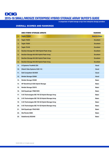
Hardware featuresIn this sectionBoard components . 5Controller specifications . 6Board componentsTwo models of the HP Smart Array P400 Controller are available. One model ("SAS/SATA connectors onthe front of the board" on page 5) has the internal SAS/SATA connectors on the front of the board, whilethe other model ("SAS/SATA connectors on the back of the board" on page 6) has the connectors on theback of the board.SAS/SATA connectors on the front of the boardItem IDDescription1SAS or SATA port 2I (internal), 4x wide SFF8484 connector.2SAS or SATA port 1I (internal), 4x wide SFF8484 connector.3Connectors for the cache module (also known as BBWC orarray accelerator).4Runtime LEDs. To interpret the illumination pattern of theseLEDs, see "Controller board runtime LEDs (on page 32)".5Cache module, showing the connector for the cable to theoptional battery pack.The cache module must be installed on the controller beforethe controller is installed in a server, or the controller will notboot.Hardware features 5
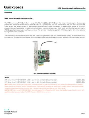
SAS/SATA connectors on the back of the boardItem IDDescription1Connectors for the cache module (also known as BBWC orarray accelerator).2SAS or SATA port 1I (internal), 4x wide SFF8484 connector.3Runtime LEDs. To interpret the illumination pattern of theseLEDs, see "Controller board runtime LEDs (on page 32)".4SAS or SATA port 2I (internal), 4x wide SFF8484 connector.5Cache module, showing the connector for the cable to theoptional battery pack.The cache module must be installed on the controller beforethe controller is installed in a server, or the controller will notboot.Controller specificationsFeatureDetailsCard typeLow-profile PCI ExpressDimensions (excluding bracket)16.8 cm 7.0 cm 1.8 cm (6.61 in 2.75 in 0.7 in)Drive types supported3.0 Gb/s SAS or 1.5 Gb/s SATAMaximum power requiredApproximately 14 WTemperature rangeOperating, 10 to 55 C (50 to 131 F)Storage, -30 to 60 C (-22 to 140 F)Relative humidity(noncondensing)Operating, 10% to 90%Storage, 5% to 90%RAID levels supported0, 1, 1 0, and 5; also RAID 6 (ADG) if the battery kit option (nextentry) is usedBattery kit option part numbersBattery pack 390936-001; battery cable 399034-001Hardware features 6
Time required to rechargebatteryFrom 15 minutes to two hours, depending on the initial battery chargelevelDuration of battery backupMore than two days if the battery is fully-charged and less than threeyears oldBattery life expectancyMore than three yearsType of edge connectorPCIe x8 (fits in slots that have a physical size of x8 or greater;operates at the speed rating of the slot, up to a maximum of x8)PCI Express support2.5 Gb/s PCI ExpressPCI Express transfer rate2.0 GB/s peak bandwidthNumber of SAS portsTwo internal wide ports; each port has four 1x connectorsSAS transfer rate1.2 GB/s per wide port peak bandwidthFor more information about the controller features and specifications, and for information about systemrequirements, refer to the HP website (http://www.hp.com/products/smartarray).Hardware features 7
Overview of the installation procedureIn this sectionInstalling the controller in an unconfigured server . 8Installing the controller in a previously configured server . 8Installing the controller in an unconfigured serverNew HP ProLiant server models self-configure when they are powered up for the first time. For moreinformation about the autoconfiguration process, refer to the server-specific setup and installation guide orthe HP ROM-Based Setup Utility User Guide. These guides are available on the server Documentation CD.IMPORTANT: Do not power up the server until the hardware configuration is satisfactory, as described inthe procedure given in this section.To install the controller in an unconfigured server:1.Install the controller hardware ("Installing the controller hardware" on page 10).2.If necessary, install physical drives.The number of drives in the server determines the RAID level that is autoconfigured when the server ispowered up (next step). For details, refer to the server-specific setup and installation guide or the HPROM-Based Setup Utility User Guide.3.Power up the server. The autoconfiguration process runs.4.Update the system firmware ("Methods for updating the firmware" on page 12).5.Update the controller firmware ("Methods for updating the firmware" on page 12).6.Install the operating system and device drivers ("Installing device drivers" on page 19). Instructionsare provided with the CD that is supplied in the controller kit.The server is now ready to use. If you want to create additional logical drives ("Configuring an array" onpage 13), you may now do so.Installing the controller in a previously configured server1.Back up any data on the system.2.Update the server firmware ("Methods for updating the firmware" on page 12).3.If the new controller is to be the boot device, install the device drivers ("Installing device drivers" onpage 19). Otherwise, continue with step 4.4.Install the controller hardware ("Installing the controller hardware" on page 10).5.Connect storage devices to the controller ("Connecting storage devices" on page 11).6.Update the controller firmware ("Methods for updating the firmware" on page 12).7.Set the controller order, using either ORCA ("Setting a controller as the boot controller" on page 18)or RBSU ("Setting the controller order" on page 18).8.If the controller is not going to be the boot device, install the device drivers ("Installing devicedrivers" on page 19).Overview of the installation procedure 8
9.Update the Management Agents ("Installing Management Agents" on page 19) if new versions areavailable.The server is now ready to use. If you want to create additional logical drives, you may now do so.Overview of the installation procedure 9
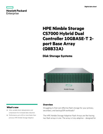
Installing the controller hardwareIn this sectionBefore beginning the installation . 10Preparing the server . 10Installing the controller board . 10Connecting storage devices. 11Before beginning the installationBefore beginning the installation procedure, visit the HP website (http://www.hp.com/support) to confirmthat you have the latest version of each driver and utility file needed. Compare the version numbers of thefiles there with those of the same files on the software CD or DVD that is supplied in the controller kit.Preparing the server1.Back up all data.2.Close all applications.3.Power down the server.CAUTION: In systems that use external data storage, be sure that the server is the first unit to be powereddown and the last to be powered back up. Taking this precaution ensures that the system does noterroneously mark the drives as failed when the server is powered up.4.Power down all peripheral devices that are attached to the server.5.Unplug the AC power cord from the outlet and then from the server.6.Disconnect all peripheral devices from the server.Installing the controller boardWARNING: To reduce the risk of personal injury or damage to the equipment, consult thesafety information and user documentation provided with the server before attemptingthe installation.Many servers are capable of providing energy levels that are considered hazardous and areintended to be serviced only by qualified personnel who have been trained to deal withthese hazards. Do not remove enclosures or attempt to bypass any interlocks that maybe provided for the purpose of removing these hazardous conditions.1.Remove or open the access panel.2.Select an available x8 or larger PCI Express slot.3.Remove the slot cover. Save the retaining screw if one is present.Installing the controller hardware 10
4.Slide the controller board along the slot alignment guide if applicable, and press the board firmlyinto the slot so that the contacts on the board edge are properly seated in the system boardconnector.5.Secure the controller board in place with the retaining screw. If there is a guide latch on the rear ofthe board, close the latch.6.Connect storage devices to the controller. (For details of the procedure, see "Connecting storagedevices (on page 11).")IMPORTANT: Drives that are to be used in the same array must be of the same type, either all SAS or allSATA. (Parallel SCSI drives cannot be used with this controller.)NOTE: Drives that are to be grouped in the same array should all have comparable capacity for efficientuse of total storage capacity.7.Close or replace the access panel, and secure it with thumbscrews, if any are present.CAUTION: Do not operate the server for long periods with the access panel open or removed. Operatingthe server in this manner results in improper airflow and improper cooling that can lead to thermal damage.Connecting storage devicesYou can connect the controller ports to internal SAS backplanes that are connected to SAS or SATAdrives. For information about the supported drive models, refer to the controller-specific page on the HPwebsite (http://www.hp.com/products/smartarray).1.Power down the system.2.Install hard drives, if necessary.IMPORTANT: Drives that are to be used in the same array must be of the same type, either all SAS or allSATA. (Parallel SCSI drives cannot be used with this controller.)NOTE: Drives that are to be grouped in the same array should all have comparable capacity for efficientuse of total storage capacity.For additional information about drive installation, see the appropriate section in this guide("Replacing, moving, or adding hard drives" on page 24) and consult the server documentation andthe documentation that accompanied the drives.3.4.Use the internal wide SAS cable provided with the server to connect the controller to the drives. If the drives are hot-pluggable, connect the internal connector of the controller to the SASconnector on the hot-plug drive cage. If the drives are not hot-pluggable, connect the internal connector of the controller to the nonhot-pluggable hard drives.Close or replace the access panel, and secure it with thumbscrews, if any are present.CAUTION: Do not operate the server for long periods with the access panel open or removed. Operatingthe server in this manner results in improper airflow and improper cooling that can lead to thermal damage.5.If the added drives are not hot-pluggable, power up the system.Installing the controller hardware 11
Updating the firmwareIn this sectionMethods for updating the firmware. 12Methods for updating the firmwareTo update the firmware on the server, controller, or hard drives, use Smart Components. Thesecomponents are available on the Firmware Maintenance CD. A more recent version of a particular serveror controller component might be available on the support page of the HP website(http://www.hp.com/support). Components for controller and hard drive firmware updates are alsoavailable from the software and drivers page for storage ).1.Find the most recent version of the component that you require. Components for controller firmwareupdates are available in offline and online formats.2.Follow the instructions for installing the component on the server. These instructions are given withthe CD and are provided on the same Web page as the component.3.Follow the additional instructions that describe how to use the component to flash the ROM. Theseinstructions are provided with each component.For more information about updating the firmware, refer to the HP ProLiant Storage FirmwareMaintenance User Guide (for controller and hard drive firmware) or the HP Online ROM Flash UserGuide (for server firmware).Updating the firmware 12
Configuring an arrayIn this sectionIntroduction . 13Comparing the utilities . 13Using ORCA. 14Using ACU . 15Using CPQONLIN. 15IntroductionHP provides four utilities for manually configuring an array on a Smart Array controller: ORCA—A simple ROM-based configuration utility ACU—A versatile, browser-based utility that provides maximum control over configurationparameters ACU CLI—A command line version of ACU CPQONLIN—A menu-based configuration utility specifically for servers using Novell NetWareFor more information about the features of these utilities, see "Comparing the Utilities (on page 13)."Whichever utility you use, be aware of the following limitations: For the most efficient use of drive space, do not mix drives of different capacities within the samearray. The configuration utility treats all physical drives in an array as if they have the same capacityas the smallest drive in the array. The excess capacity of any larger drives is wasted because it isunavailable for data storage. All drives in an array must be of the same type (for example, all SAS or all SATA). The probability that an array will experience a drive failure increases with the number of physicaldrives in the array.For conceptual information about arrays, logical drives, and fault-tolerance methods, and for informationabout default array configuration settings, refer to the HP Array Configuration Utility User Guide. Thisdocument is available on the Documentation CD that is provided in the controller kit.Comparing the utilitiesNOTE: A in the appropriate column indicates that the feature or procedure is supported, while -- indicatesthat the feature or procedure is not supported.Supported featuresACUCPQONLINORCAUses a graphical interface ----Available in languages other than English ----Executable at any time Only during POSTAvailable on CD CD not necessary;located in ROMConfiguring an array13
Supported featuresACUCPQONLINORCAUses a wizard to suggest the optimum configuration foran unconfigured controller --Describes configuration errors ----Supported proceduresACUCPQONLINORCACreation and deletion of arrays and logical drives Assignment of RAID level Sharing of spare drives among several arrays --Assignment of multiple spare drives per array --Setting of stripe size --Migration of RAID level or stripe size --Configuration of controller settings --Expansion of an array --Creation of multiple logical drives per array --Setting of boot controller---- Using ORCA1.Power up the server.POST runs, and all controllers in the server are initialized one at a time in the current boot ordersequence. If a controller is connected to one or more hard drives, an ORCA prompt messageappears during the initialization process for that controller.2.At the ORCA prompt for the controller that you want to configure, press the F8 key.The ORCA main menu appears, enabling you to create, view, or delete a logical drive.To create a logical drive using ORCA:1.Select Create Logical Drive.The screen displays a list of all available (unconfigured) physical drives and the valid RAID optionsfor the system.2.Use the Arrow keys, Spacebar, and Tab key to navigate around the screen and set up thelogical drive, including an online spare drive if one is required.Configuring an array14
NOTE: You cannot use ORCA to configure one spare drive to be shared among several arrays. Only ACUenables you to configure shared spare drives.3.Press the Enter key to accept the settings.4.Press the F8 key to confirm the settings and save the new configuration.After several seconds, the Configuration Saved screen appears.5.Press the Enter key to continue.You can now create another logical drive by repeating the previous steps.NOTE: Newly created logical drives are invisible to the operating system. To make the new logical drivesavailable for data storage, format them using the instructions given in the operating system documentation.Using ACUFor detailed information about using ACU, refer to the HP Array Configuration Utility User Guide. Thisdocument is available on the Documentation CD that is provided in the controller kit.Using CPQONLINThe NetWare Online Array Configuration Utility (CPQONLIN) is an NLM that enables you to configuredrive arrays on a NetWare server without powering down the server or storage system. CPQONLIN alsoprovides information about the status of drives attached to the controller.NOTE: CPQONLIN can only be used while the server is online. If you want to configure an array when theserver is offline, you must use ACU instead.To run CPQONLIN:1.Use the software CD provided with the controller to load the drivers (HPQCISS.HAM andCPQSHD.CDM) and the executable (CPQONLIN.NLM) on the server. Detailed instructions areprovided with the CD.2.Enter cpqonlin at the console prompt.3.Use the arrow keys to highlight the Array Configuration Utility menu item, and then press the Enterkey.4.From the list of controllers that is presented, select the one that you want to configure.5. If there are no logical drives connected to the controller, an auto-configuration wizard opensand prompts you for fault-tolerance information. If the controller is connected to at least one logical drive, CPQONLIN continues in manualconfiguration mode. Use the arrow and Enter keys to navigate around the screen and set upthe logical drive. To get online help at any time, press the F1 key.When you have finished configuring the array, save the changes.NOTE: Newly created logical drives are invisible to the operating system. To make the new logical drivesavailable for data storage, format them using the instructions given in the operating system documentation.The following sections provide details of some typical procedures.Setting drive rebuild, expand priority, and accelerator ratio1.Go to the Main Configuration View screen.2.Highlight the controller.Configuring an array15
3.Select the Controller Settings option below Controller Options. The Controller Settings screenappears.Drive rebuildDrive rebuild occurs after a physical drive fails and is replaced. Only logical drives that are configuredwith RAID 1 0, RAID 5, or RAID 6 (ADG) can be rebuilt.Priority settingsTo set the drive rebuild priority:1.Highlight the controller.2.Select the controller settings: If you choose low priority for drive rebuild, drive rebuilding occurs when I/O to the drive isinactive. If you choose high priority, drive rebuilding occurs faster, at the expense of normal I/Ooperations.Accelerator ratioThe controller has an onboard cache called an Array Accelerator, which performs both write-posting andread-ahead caching. The setting in CPQONLIN determines the amount of memory allocated to the readand write caches.For example, if the accelerator ratio is set to Read 75%:Write 25%, 75% of Array Accelerator cache isdedicated to read-ahead cache and 25% i
Connect storage devices to the controller ("Connecting storage devices" on page 11). 6. Update the controller firmware ("Methods for updating the firmware" on page 12). 7. Set the controller order, using either ORCA ("Setting a controller as the boot controller" on page 18) or RBSU ("Setting the controller order" on page 18). 8.