Transcription
SLC 5/01 and SLC 5/02 ModularProcessors(Catalog Numbers 1747-L511, 1747-L514,1747-L524)Installation InstructionsInside.pageEnglish Section . . . . . . . . . . . . . . . . 3Section en francais . . . . . . . . . . . . . 15Deutscher Abschnitt . . . . . . . . . . . . 27Sezione italiana . . . . . . . . . . . . . . . 39Sección en español . . . . . . . . . . . . 51
SLC 5/01 and SLC 5/02 ModularProcessors(Catalog Numbers 1747-L511, 1747-L514,1747-L524)Installation InstructionsEnglish SectionInside.pageImportant User Information . . . . . . . . .4For More Information . . . . . . . . . . . . 5Required Tools and Equipment . . . . 6Safety Considerations . . . . . . . . . . . 6Installation Procedure . . . . . . . . . . . 7Troubleshooting . . . . . . . . . . . . . . . . 9Specifications . . . . . . . . . . . . . . . . . 10Battery Handling, Storing, andTransporting (Cat. No. 1747-BA) . . 12
4Important User InformationBecause of the variety of uses for the products described in this publication, thoseresponsible for the application and use of this control equipment must satisfythemselves that all necessary steps have been taken to assure that eachapplication and use meets all performance and safety requirements, including anyapplicable laws, regulations, codes and standards.The illustrations, charts, sample programs and layout examples shown in thisguide are intended solely for purposes of example. Since there are manyvariables and requirements associated with any particular installation,Allen-Bradley does not assume responsibility or liability (to include intellectualproperty liability) for actual use based upon the examples shown in thispublication.Allen-Bradley publication SGI-1.1, Safety Guidelines for the Application,Installation, and Maintenance of Solid-State Control (available from your localAllen-Bradley office), describes some important differences between solid-stateequipment and electromechanical devices that should be taken into considerationwhen applying products such as those described in this publication.Reproduction of the contents of this copyrighted publication, in whole or in part,without written permission of Allen-Bradley Company, Inc., is prohibited.Throughout these installation instructions we use notes to make you aware ofsafety considerations:!ATTENTION: Identifies information about practices orcircumstances that can lead to personal injury or death, propertydamage or economic lossAttention statements help you to: identify a hazard avoid the hazard recognize the consequencesImportant: Identifies information that is critical for successful application andunderstanding of the product.Publication 1747-5.25
5For More InformationAs part of our effort to preserve, protect, and improve our environment,Allen-Bradley is reducing the amount of paper we use. Less paper means moreoptions for you. In addition to traditional printed publications and CD-ROMversions, we now offer on-line manuals with the most up-to-date information youcan get. We recommend that you read the related publications listed belowbefore starting up your control system.Related PublicationsForRefer to this DocumentPub. No.A more detailed description on how toinstall and use your modular SLC 500system.SLC 500 ModularHardware Style Installationand Operation Manual1747-6.2A reference manual that contains statusfile data, instruction set, andtroubleshooting information.SLC 500 and MicroLogix1000 Instruction SetReference Manual1747-6.15A CD–ROM containing both of themanuals listed above, plus the: SLC 500 Analog I/O Modules UserManual Discrete I/O Modules InstallationInstructions Discrete I/O Modules Product DataSLC 500 LiteratureCollection on CD–ROM1747-CD1-1If you would like a manual, you can: download a free electronic version from the internet:www.theautomationbookstore.com purchase a printed manual by:— contacting your local distributor or Rockwell Automationrepresentative— visiting www.theautomationbookstore.com and placing your order— calling 1.800.963.9548 (USA/Canada) or001.330.725.1574 (Outside USA/Canada)Publication 1747-5.25
6Required Tools and Equipment medium blade screwdriver programming equipment a 1747-PIC, 1784-KTX, or 1784-PCMK communication interfacesSafety Considerations!ATTENTION: Never install, remove, or wire any module whilepower is applied. Also, do not expose processor modules tosurfaces or other areas that may typically hold an electrostaticcharge. Electrostatic charges can alter or destroy memory.For general recommendations concerning installation safety requirements andsafety related work practices, refer to the requirements specific to your region. Europe: Reference the standards found in EN 60204 and your nationalregulations. United States: refer to NFPA 70E, Electrical Safety Requirements forEmployee Workplaces.Important: See page 10 for information on proper battery handling, storage, andtransporting.Publication 1747-5.25
7Installation ProcedureInstall the BatteryImportant: If your processor has a battery— the battery is an option for the SLC5/01 (1747-L511) processor — make sure it is connected beforeinstalling your processor into the chassis. This provides memorybackup for your processor should the controller power supply fail.1. Open the door of the processor.2. Remove the jumper from the battery connector socket. Store the jumper ina safe place for possible future use without the battery.3. Insert a new or replacement battery in the holder making sure it is held in bythe retainer clips.4. Plug the battery connector into the socket. See the figure s 5. Close the processor door.Important: See page 10 for information on proper battery handling, storage, andtransporting.Publication 1747-5.25
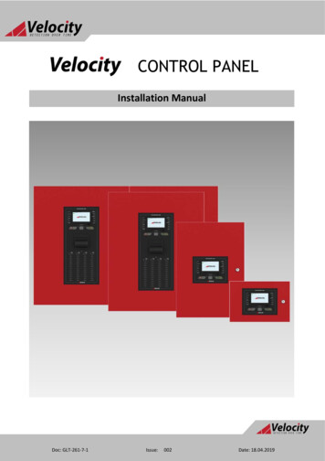
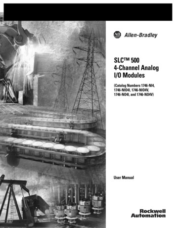
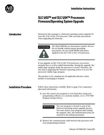
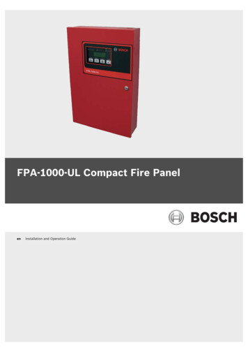
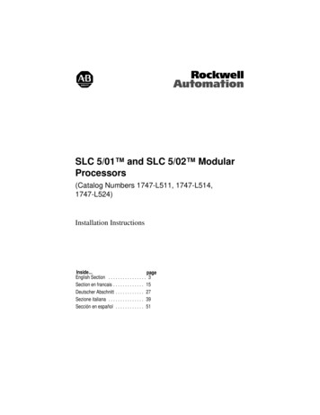
8Install the ProcessorMake sure system power is off; then insert the processor into slot 0 of the 1746chassis.Important: The SLC 500t Modular Processors must be inserted into the left slot(slot 0), as shown below. In addition, remove the protective wrap afterinstalling the processor.PowerSupplyProcessorReleaseCard GuideProtective WrapApply Power to the Processor1. Energize the chassis power supply.2. Check the chassis power supply and processor LEDs. The power LED on thepower supply should be on and the fault LED on the processor should beflashing.Indicates the LED is OFF.POWERCOMMRUNCPU FAULTFORCED I/OBATTERY LOWIndicates the LED is ON.Indicates the LED isFLASHING.Status of LED does not matter.The RUN LED on the SLC 5/01processor is actully labeled “PCRUN.” Also, the SLC 5/01 processordoes not have a COMM LED.Publication 1747-5.25
9Load Your SoftwareRefer to your programming software documentation.Establish Communications with the Processor1. Connect the 1747-PIC to the processor and your personal computer.2. Set the communication parameters of the software to match the defaultparameters of the processor:— DH-485— 19.2k baud— Node Address 1TroubleshootingBefore troubleshooting your SLC 500 system, please obtain an SLC 500 ModularHardware Style Installation and Operation Manual (1747-6.2) from one of thesources listed on page 3. Refer to the chapter on Troubleshooting.In addition to the SLC 500 Modular Hardware Style Installation and OperationManual, the SLC 500 and MicroLogix 1000 Instruction Set Reference Manual(1747-6.15) may also be obtained from the sources listed on page 3. This manualcontains explanations and examples for the entire instruction set as well as for allstatus words and bits. It also contains explanations for all possible fault codesfound in status word S:6.Publication 1747-5.25
10SpecificationsSLC 5/01(1747-L511, -L514)SpecificationSLC 5/02(1747-L524)Program Memory1K or 4K Instructions4K InstructionsAdditional Data Storage00Maximum I/O Capacity3940 discrete inputs3940 discrete outputs4096 discrete inputs4096 discrete outputsMax. Local Chassis/Slots3/303/30Programming SoftwareRSLogix 500 , PLC– 500 A.I. Series , APS, and HHTProgramming Instructions5271Typical Scan Time(1)8 ms/K4.8 ms/KBit Execution (XIC)4 µs2.4 µs(1)The scan times are typical for a 1K ladder logic program consisting of simple ladder logic andcommunication servicing. Actual scan times depend on your program size, instuctions used, andthe communication protocol.CommunicationDH-485(1)ReceiveSLC 5/01(1)Receive or InitiateSLC 5/02(1)A 1747-PIC is required when connecting to the DH-485 channel for programming.Publication 1747-5.25
11DescriptionSpecificationPower Supply Loading at 5V dc350 mAPower Supply Loading at 24V dc105 mAProgram Scan Hold-up Time after Loss ofPower20 ms to 3 s (dependent on power supply loading)Noise ImmunityNEMA Standard ICS 2-230VibrationDisplacement: 0.015 inch, peak-to-peak at 5-57HzAcceleration: 2.5Gs at 57-2000 HzShock (operating)30GsAmbient Temperature RatingOperating: 0 to 60 C (32 F to 140 F)Storage: 40 C to 85 C (-40 F to 185 F)Humidity5 to 95% without condensationAgency CertificationUL listedCSA approvedClass 1, Groups A, B, C or D, Division 2CE compliant for all applicable directivesThe following table summarizes the available memory back up options for theSLC 5/01 and SLC 5/02 processors. EEPROM and UVPROM memory modulesprovide non-volatile memory back-up.Memory Back Up OptionSLC 5/01(1747-L511/1747-L514)SLC 5/02(1747-L524)EEPROM1747-M1, 1747-M21747-M2UVPROM1747-M3, 1747-M41747-M4Publication 1747-5.25
12Battery Handling, Storing, and Transporting (Cat. No. 1747-BA)Handling!ATTENTION: Do not charge the batteries. An explosion couldresult or the cells could overheat causing burns.Do not open, puncture, crush, or otherwise mutilate the batteries.An explosion may result and/or toxic, corrosive, and flammableliquids would be exposed.StoringStore the lithium batteries in a cool, dry environment, typically 20 C to 25 C( 68 F to 77 F) and 40% to 60% relative humidity.TransportingOne or Two Batteries — Up to two batteries can be shipped together within theUnited States without restriction. Regulations governing shipment to or withinother countries may differ.Three or More Batteries — Procedures for the transportation of three or morebatteries shipped together within the United States are specified by theDepartment of Transportation (DOT) in the Code of Federal Regulations,CFR49, “Transportation.” An exemption to these regulations, DOT - E7052,covers the transport of certain hazardous materials classified as flammable solids.This exemption authorizes transport of lithium batteries by motor vehicle, railfreight, cargo vessel, and cargo-only aircraft, providing certain conditions aremet. Transport by passenger aircraft is not permitted.Shipment of depleted batteries for disposal may be subject to specific regulationof the countries involved or to regulations endorsed by those countries, such asthe IATA Restricted Articles Regulations of the International Air TransportAssociation, Geneva, Switzerland.Important:Regulations for transportation of lithium batteries are periodicallyrevised.Publication 1747-5.25
13!ATTENTION: Do not incinerate or dispose of lithium batteries ingeneral trash collection. Explosion or violent rupture is possible.Batteries should be collected for disposal in a manner to preventagainst short circuiting, compacting, or destruction of case integrityand hermetic seal.For disposal, batteries must be packaged and shipped in accordance withtransportation regulations, to a proper disposal site. The U.S. Department ofTransportation authorizes shipment of “Lithium batteries for disposal” by motorvehicle only in regulation 173.1015 of CFR 49 (effective January 5, 1983). Foradditional information contact:U.S. Department of TransportationResearch and Special Programs Administration400 Seventh Street, S.W.Washington, D.C. 20590Although the Environmental Protection Agency at this time has no regulationsspecific to lithium batteries, the material contained may be considered toxic,reactive, or corrosive. The person disposing of the material is responsible for anyhazard created in doing so. State and local regulations may exist regarding thedisposal of these materials.For a lithium battery material safety data sheet, contact the manufacturer:Sanyo Energy Corporation600 Supreme DriveBensenville, IL 60106Publication 1747-5.25
Processeurs modulaires SLC 5/01 et SLC 5/02 (Références 1747-L511, 1747-L514, 1747-L524)Notice d’installationSection en francaisContenu.pageInformations utilisateur . 16Complément d’informations . 17Outils et équipement requis . 18Considérations de sécurité . 18Procédure d’installation . 19Dépannage . 21Spécifications . 22Manipulation, stockage et transport de piles(Réf. 1747-BA) . 24
16Informations utilisateurEn raison de la diversité des utilisations des produits décrits dans le présentmanuel, les personnes responsables de l’équipement doivent s’assurer que toutesles mesures ont été prises pour que l’application et l’utilisation des produitssoient conformes aux exigences de performance et de sécurité, ainsi qu’aux lois,règlements, codes et normes en vigueur.Les illustrations, schémas et exemples de programmes contenus dans ce manuelsont présentés à titre indicatif seulement. En raison des nombreuses variables etimpératifs associés à chaque installation, la société Allen-Bradley ne saurait êtretenue pour responsable ou redevable (y compris en matière de propriétéintellectuelle) des suites d’utilisation réelle basée sur les exemples et schémasprésentés dans ce manuel.La publication SGI-1.1, Safety Guidelines for the Application, Installation, andMaintenance of Solid-State Control (disponible auprès de votre agencecommerciale Allen-Bradley) décrit certaines différences importantes entre leséquipements électroniques et les équipements électromécaniques qui devront êtreprises en considération lors de l’application de ces produits comme indiqué dansla présente publication.Toute reproduction partielle ou totale du présent manuel sans autorisation écritede la société Allen-Bradley est interdite.Des remarques sont utilisées tout au long de ce manuel pour attirer votre attentionsur les mesures de sécurité à prendre en compte :!ATTENTION: Indique les informations sur les pratiques oucirconstances pouvant entraîner des dommages corporels, dégâtsmatériels ou pertes financières.Les encarts Attention vous aident à : identifier un danger éviter un danger discerner les conséquencesImportant:Indique les informations déterminantes pour la bonnecompréhension et application du produit.Publication 1747-5.25
17Complément d’informationsDans le cadre des efforts de protection, de sauvegarde et d’amélioration del’environnement, Allen-Bradley réduit la quantité de papier utilisé. Moins depapier, c’est aussi un plus grand choix pour les utilisateurs : outre les publicationsimprimées traditionnelles et versions sur CD-ROM, nous vous offronsmaintenant des manuels en ligne comportant les informations les plus récentes.Nous vous recommandons de lire les publications associées, énuméréesci-dessous, avant de lancer votre système de commande.Publications associéesPourVoir ce documentRéf.Une description plus détaillée de l’installation etde l’utilisation de votre système modulaire SLC500.SLC 500 ModularHardware StyleInstallation and OperationManual1747-6.2Un manuel de référence comportant desinformations sur les données du fichier d’état, lejeu d’instructions et le dépannage.Manuel de référence et dejeu d’instructions SLC 500et MicroLogix 10001747-6.15FREnsemble des manuelsSLC 500 sur CD-ROM1747-CD1-1Un CD-ROM contenant les manuels énumérésci-dessus plus : Manuel d’utilisation des modules d’E/Sanalogiques SLC 500 Notice d’installation des modules d’E/S TOR Description produit des modules d’E/S TORComment obtenir plus d’informationsPour vous procurer un manuel, vous pouvez : le charger gratuitement depuis le site Internet :www.theautomationbookstore.com acheter un manuel imprimé. Pour cela :— contactez votre distributeur local Rockwell Automation— visitez www.theautomationbookstore.com et commandez-le enligne— appelez le 1.800.963.9548 (USA/Canada)ou le 001.330.725.1574 (hors USA/Canada)Publication 1747-5.25
18Outils et équipement requis un tournevis plat de taille moyenne un équipement de programmation une interface de communication 1747-PIC, 1784-KTX ou 1784-PCMKConsidérations de sécurité!ATTENTION: Ne jamais installer, retirer ou câbler un modulesous tension. N’exposez pas les modules processeurs aux surfacesou autres zones généralement soumises à des chargesélectrostatiques. Les charges électrostatiques peuvent endommagerou détruire la mémoire.Pour connaître les recommandations générales relatives aux impératifs desécurité d’installation et de protection des postes de travail, reportez-vous auxnormes en vigueur dans votre région. Europe : Référence aux normes EN 60204 et aux réglementationsnationales. Etats–Unis : Référence au NFPA 70E, « Electrical Safety Requirements forEmployee Workplaces ».Important: Pour plus d’informations sur la manipulation, le stockage et letransport des piles, reportez-vous à la page 23.Publication 1747-5.25
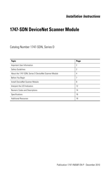
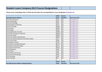
19Procédure d’installationInstallation de la pileImportant: Si votre processeur est équipé d’une pile — la pile est une option duprocesseur SLC 5/01 (1747-L511) — assurez-vous qu’elle estconnectée avant d’installer le processeur dans le châssis. La pileassure la sauvegarde de la mémoire en cas de coupure de courant devotre processeur.1. Ouvrez la porte du processeur.2. Retirez le cavalier de la fiche du connecteur de la pile. Conservez le cavalierdans un endroit sûr afin de pouvoir l’utiliser ultérieurement sans la pile.3. Insérez une nouvelle pile ou une pile de rechange dans le support en veillantà ce qu’elle soit retenue par les clips de blocage.4. Branchez le connecteur de la pile dans la fiche. Voir figure ci-dessous.FilblancFilrougeConnecteurde la pileClips deblocage 5. Refermez la porte du processeur.Important: Pour plus d’informations sur la manipulation, le stockage et letransport des piles, reportez-vous à la page 23.Publication 1747-5.25
20Installation du processeurAssurez-vous que l’alimentation est hors tension, puis insérez le processeur dansl’emplacement 0 du châssis 1746.Important: Les processeurs modulaires SLC 500t doivent être insérés dansl’emplacement de gauche (emplacement 0), comme illustréci-dessous. Retirez la bande de protection après avoir installé leprocesseur.AlimentationLoquet duprocessorGuide-carteBande de protectionMise sous tension du processeur1. Mettez l’alimentation du châssis sous tension.2. Surveillez les LED de l’alimentation et du processeur. La LED « POWER »de l’alimentation doit être allumée et la LED d’erreur du processeur doitclignoter.POWERCOMMRUNCPU FAULTFORCED I/OBATTERY LOWIndique que la LED est éteinte.Indique que la LED est allumée.Indique que la LED clignote.L’etat de la LED n’a pas d’importanceLa LED RUN du processeur SLC 5/01 estappelée PC RUN. Le processeur SLC 5/01 n’a pas de LED COMM.Publication 1747-5.25
21Chargement de votre logicielRéferez-vous à la documentation de votre logiciel de programmation.Establissement des communications avec le processeur1. Connectez le 1747-PIC au processeur et à votre ordinateur personnel.2. Définissez les paramètres de communication du logiciel en fonction desparamètres par défaut du processeur : DH-485 19,2 kbauds Adresse de poste 1DépannageAvant de commencer à dépanner votre système SLC 500, veuillez vous procurerle Manuel d’installation et de fonctionnement des SLC 500 modulaires(1747-6.2) auprès d’une des sources de documentation présentées en page 16.Référez-vous au chapitre relatif au dépannage.Outre le manuel précité, le Manuel de référence et jeu d’instructions du SLC 500et du MicroLogix 1000 (1747-6.15FR) peut également être obtenu auprès dessources de documentation présentées en page 16. Ce manuel comporte desexplications et exemples pour l’ensemble du jeu d’instructions ainsi que pourtous les mots et bits d’états. Il comporte également les explications de tous lescodes d’erreur possibles contenus dans le mot d’état S:6.Publication 1747-5.25
22SpécificationsSLC 5/01(1747-L511, -L514)SpécificationSLC 5/02(1747-L524)Mémoire programme1 K ou 4 K instructions4 K instructionsStockage de donnéessup.00Capacité d’E/S maximum3940 entrées TOR3940 sorties TOR4096 entrées TOR4096 sorties TORNbre maxi de châssislocaux/emplacements3/303/30Logiciel deprogrammationRSLogix 500t, PLC-500 A.I. Seriest, APS et HHTInstructions deprogrammation5271Durée de scrutationtype(1)8 ms/K4,8 ms/KExécution de bit (XIC)4 µs2,4 µs(1)Les durées de scrutation sont généralement calculées pour un programme de logique à relais 1 Kcomposé d’une logique à relais simple et du traitement des communications. Les durées descrutations réelles dépendent de la taille de votre programme, des instructions utilisées et duprotocole de communication.CommunicationDH-485(1)RéceptionSLC 5/01(1)Réception ou envoiSLC 5/02(1)Un 1747-PIC est nécessaire pour la connexion de la voie DH-485 à des fins deprogrammation.Publication 1747-5.25
23DescriptionSpécificationIntensité de l’alimentation à 5 V c.c.350 mAIntensité de l’alimentation à 24 Vc.c.105 mATemps de maintien de la scrutationdu programme après perted’aliementationde 20 ms à 3 s (selon l’intensité de l’alimentation)Immunité au bruitNorme NEMA ICS 2-230Résistance aux vibrationsDéplacement : 0,015 in, crête à crête à 5-57 HzAccélération : 2,5 G à 57-2000 HzTenue aux chocs (en service)30 GPlage des températuresEn fonctionnement : de 0 à 60 C (de 32 F à 140 F)Stockage : de 40 C à 85 C (de -40 F à 185 F)Humidité ambiantede 5 à 95 % sans condensationHomologationListé ULApprouvé CSAClasse 1, Groupes A, B, C ou D, Division 2Conforme CE pour toutes les directives en vigueurLe tableau suivant résume les options de mémoire de sauvegarde disponiblespour les processeurs SLC 5/01 et SLC 5/02. Les modules mémoire EEPROM etUVPROM assurent une sauvegarde de la mémoire non volatile.Option de sauvegarde de lamémoireSLC 5/01(1747-L511/1747-L514)SLC 5/02(1747-L524)EEPROM1747-M1, 1747-M21747-M2UVPROM1747-M3, 1747-M41747-M4Publication 1747-5.25
24Manipulation, stockage et transport de piles (Réf. 1747-BA)Manipulation!ATTENTION: Ne pas ouvrir, percer, écraser ou détériorer lespiles. Une explosion pourrait se produire et/ou exposer dessubstances inflammables, corrosives et toxiques. Ne pasrecharger les piles. Une explosion pourrait se produire et lasurchauffe des éléments de la pile pourrait provoquer desbrûlures.StockageStockez les piles au lithium dans un endroit sec et frais, entre 20 C et 25 C( 68 F et 77 F) et une humidité ambiante comprise entre 40 % et 60 %.TransportUne ou deux piles — Vous pouvez envoyer jusqu’à deux piles à l’intérieur desEtats-Unis sans aucune restriction. Les réglementations relatives à l’expéditionpeuvent varier d’un pays à l’autre.Trois piles ou plus — Les procédures de transport de trois piles ou plus àl’intérieur des Etats-Unis sont spécifiées par le Ministère américain destransports (Department of Transportation - DOT) dans le code desréglementations fédérales (Code of Federal Regulations), CFR49, «Transportation ». Certains matériaux classés comme solides inflammablesbénéficient d’une exemption DOT - E7052 à cette réglementation. Cetteexemption autorise le transport des piles au lithium par véhicule à moteur, frêtferrovière, maritime et avion cargo sous certaines conditions. Le transport paravion passager est interdit.L’expédition de piles déchargées pour mise au rebut est soumise aux réglementsspécifiques du pays concerné ou aux réglements avalisés par lesdits pays, tels quelmes réglementations d’articles restrictifs de l’IATA (l’International AirTransport Association), Genève.Important: Les réglementations du transport des piles au lithium sont réviséespériodiquement.Publication 1747-5.25
25!ATTENTION: Ne pas incinérer ou jeter les piles au lithium dansdes conteneurs non prévus à cet effet. Une explosion ou unerupture pourrait se produire. Les piles doivent être collectées pourla mise au rebut de façon à éviter les court-circuits, le compactageou la destruction du boîtier hermétique et de son enveloppehermétique.Pour la mise au rebut, les piles doivent être emballées et expédiées vers un siteapproprié conformément aux réglementations de transport. Le Ministèreaméricain des transports autorise l’expédition de « piles au lithium pour la miseau rebut » par véhicule à moteur dans son réglement 173.1015 de CFR 49 (envigueur depuis le 5 janvier 1983). Pour toute information complémentaire,adressez-vous à :U.S. Department of TransportationResearch and Special Programs Administration400 Seventh Street, S.W.Washington, D.C. 20590Bien que l’Agence américaine de protection de l’environnement n’ait pasactuellement de réglementation spécifique aux piles au lithium, la matièrecontenue dans ces piles est considérée comme toxique, réactive et corrosive. Lapersonne en charge de la mise au rebut de ces matières est responsable de toutrisque résultant de son action. Des réglementations nationales et locales relativesà la mise au rebut de ces matières peuvent exister.Pour obtenir une fiche technique de sécurité sur les piles au lithium,adressez-vous au fabricant :Sanyo Energy Corporation600 Supreme DriveBensenville, IL 60106Publication 1747-5.25
Modulare Prozessoren SLC 5/01 und SLC 5/02 (Bestellnummern 1747-L511, 1747-L514,1747-L524)InstallationsdatenDeutscher AbschnittInhalt.SeiteWichtige Anwendungshinweise . . . . . . . . . . . 28Weitere Informationen . . . . . . . . . . . . . . . . . . 29Erforderliche Werkzeuge und Geräte . . . . . . . 30Sicherheitshinweise . . . . . . . . . . . . . . . . . . . . 30Einbauverfahren . . . . . . . . . . . . . . . . . . . . . . . 31Störungssuche . . . . . . . . . . . . . . . . . . . . . . . . 33Technische Daten . . . . . . . . . . . . . . . . . . . . . . 34Handhabung, Lagerung und Transport der Batterie(Best.-Nr. 1747-BA) . . . . . . . . . . . . . . . . . . . . 36Publikation 1747-5.25
28Wichtige AnwendungshinweiseAufgrund der vielfältigen Einsatzmöglichkeiten der in dieser Publikationbeschriebenen Produkte müssen Sie als Verantwortlicher für die Anwendung undNutzung dieses Geräts sicherstellen, daß jede Anwendung bzw. jeder Einsatz alleLeistungs- und Sicherheitsanforderungen, einschließlich sämtlicheranwendbaren Gesetze, Vorschriften, Codes und Normen erfüllt.Die in diesem Handbuch dargestellten Abbildungen, Tabellen, Programm- undLayout-Beispiele sind ausschließlich zur besseren Texterläuterung diesesHandbuchs aufgeführt. Aufgrund der vielfachen Möglichkeiten undAnforderungen jedes einzelnen Verwendungszwecks kann Allen-Bradley keineVerantwortung oder Haftung (einschließlich Haftung für geistiges Eigentum) fürden tatsächlichen Einsatz, der auf den in dieser Publikation enthaltenenBeispielen beruht, übernehmen.Die Allen-Bradley Publikation SGI-1.1, Safety Guidelines for the Application,Installation, and Maintenance of Solid-State Controls (erhältlich über Ihreörtliche Allen-Bradley Geschäftsstelle) behandelt einige wichtige Unterschiedezwischen elektronischen und elektromechanischen Geräten, die bei derAnwendung der in dieser Publikation beschriebenen Produkte berücksichtigtwerden sollten.Die Vervielfältigung des Inhalts dieses verlagsrechtlich geschützten Handbuchs,ganz oder auszugsweise, bedarf der schriftlichen Genehmigung derAllen-Bradley Company, Inc.Besondere Hinweise in diesem Handbuch sollen den Anwender auf bestimmteSicherheitsaspekte aufmerksam machen:!ACHTUNG: Diese Hinweise sollen den Leser auf Vorgehensweisen und Zuständeaufmerksam machen, die Körperverletzungen oder sogar Tod sowieGeräteschäden oder wirtschaftliche Verluste zur Folge haben können.Die Achtungshinweise helfen Ihnen: Gefahrenzustände zu erkennen Gefahren zu vermeiden Folgeschäden zu erkennenWichtig:Kennzeichnet Informationen, die für die erfolgreiche Anwendungsowie für ein gründliches Verstehen des Produkts unabdingbar sind.Publikation 1747-5.25
29Weitere InformationenIn unseren Bemühungen, die Umwelt zu erhalten, zu schützen und zu verbessern,reduzieren wir bei Allen-Bradley die Papiermenge, die wir einsetzen. WenigerPapier bedeutet mehr Alternativen für Sie. Neben den herkömmlichengedruckten Publikationen bieten wir nun Online-Handbücher an, die aktuellsteDaten enthalten. Vor der Inbetriebnahme des Steuerungssystems empfehlen wirdas Lesen der unten aufgeführten themenverwandten Publikationen.Themenverwandte PublikationenInformationen über:Dokumentation:Publik.–Nr.Detailliertere Beschreibung über dieInstallation und Anwendung von SLC500-Steuerungssystemen mit festerHardware-KonfigurationSLC 500 Modular Hardware StyleInstallation and Operation Manual1747-6.2Referenzhandbuch mitStatusfiledaten, Befehlssatz undHinweisen zur StörungssucheBefehlssatz für SLC 500und MicroLogix 1000Referenzhandbuch1747-6.15DEgesammelte SLC500-Publikationen auf CD-ROM1747-CD1-1Die beiden oben aufgeführtenHandbücher sowie die folgendenPublikationen auf CD-ROM: Analog-E/A-Module SLC 500,Benutzerhandbuch Diskrete E/A-Module,Installationsdaten Diskrete E/A-Module, ProduktdatenZusätzliche InformationenZu diesem Produkt gibt es eine Benutzerhandbuch, das Sie wie folgt bestellenkönnen: durch kostenloses Herunterladen vom Internet:www.theautomationbookstore.com durch Erwerb:— bei Ihrem Distributor oder einer Niederlassung von RockwellAutomation in Ihrer Nähe— per Internet: www.theautomationbookstore.com— per Telefon unter folgenden Rufnummern:1.800.963.9548 (USA/Kanada)oder 001.330.725.1574 (außerhalb den USA/Kanadas)Publikation 1747-5.25
30Erforderliche Werkzeuge und Geräte mittelgroßer Flachschraubendreher Programmiergerät Kommunikationsschnittstelle 1747-PIC,
Check the chassis power supply and processor LEDs. The power LED on the power supply should be on and the fault LED on the processor should be flashing. POWER RUNCOMMCPU FAULTFORCED I/OBATTERY LOW Indicates the LED is OFF. Indicates the LED is ON. Indicates the LED is FLASHING. Status of LED does not matter.