Transcription
High Availability SSO DeploymentGuide for Cisco Catalyst 9800Series Wireless Controllers, CiscoIOS XE Amsterdam 17.1First Published: March 12, 2020Cisco Systems, Inc.www.cisco.com1
High Availability SSO Deployment Guide for Cisco Catalyst 9800 Series Wireless Controllers, Cisco IOSXE Amsterdam 17.1IntroductionTable of ContentsIntroduction . 4Overview . 4Feature Description and Functional Behavior . 4Platforms Supported . 5SSO Pre-requisites . 5SSO on Cisco Catalyst C9800-40-K9 and C9800-80-K9 Wireless Controllers . 5Physical Connectivity for C9800-L, C9800-40 and C9800-80 Wireless Controller HA SSO . 6Connecting C9800-L Wireless Controllers using RJ-45 RP Port for SSO . 6Connecting C9800-40 and 9800-80 Wireless Controllers using RJ-45 RP Port for SSO . 7Connecting C9800-40 and 9800-80 Wireless Controllers using SFP Gigabit RP Port for SSO. 7Connecting a C9800 wireless controller HA pair to upstream switches. 7Option 1: Single VSS switch (or stack/VSL pair/modular switch) with RP back-to-back . 8Option 2: Single VSS switch (or stack/VSL pair/modular switch) with RP via upstream . 9Option 3: Dual Distributed switches with HSRP . 9Connecting a C9800 wireless controller HA pair to upstream switches with Release 17.1and above. 9SSO on Cisco Catalyst C9800-CL running on ESXi, KVM, Hyper-V . 10Configuring High Availability SSO using GUI. 10Mobility MAC configuration . 12Configuring High Availability SSO using CLI . 12Active and Standby Election Process . 12State Transition for HA SSO Pair formation . 13Monitoring the HA Pair . 15Monitoring HA Pair from CLI . 17Verifying Redundancy States . 18Accessing standby wireless controller console . 20Switchover Functionality . 21Process Failure Switchover . 21Power-fail Switchover . 21Manual Switchover . 21Failover Process . 222
High Availability SSO Deployment Guide for Cisco Catalyst 9800 Series Wireless Controllers, Cisco IOSXE Amsterdam 17.1IntroductionActive wireless controller . 22Standby wireless controller . 22Verifying AP and Client SSO State Sync . 23SSO Failover Time Metrics . 23Redundancy Management Interface . 23Redundancy Management Interface Configuration using WebUI . 24Redundancy Management Interface Configuration using CLI . 24Verifying RMI and RP configuration . 25RMI and RP pairing combinations . 26Upgrade and HA Pairing with no previous HA config . 26Upgrade already Paired controllers . 26Downgrade . 26Default Gateway Check. 27Default Gateway Check WebUI Configuration . 28Default Gateway Check CLI Configuration . 29System and Network Fault Handling . 29HA Unpairing Behavior . 33LACP, PAGP support in SSO Pair . 34Supported LACP, PAGP topologies . 34N 1 with SSO Hybrid deployment . 353
High Availability SSO Deployment Guide for Cisco Catalyst 9800 Series Wireless Controllers, Cisco IOSXE Amsterdam 17.1IntroductionIntroductionHigh availability has been a requirement on wireless controllers to minimize downtime in live networks. Thisdocument provides information on the theory of operation and configuration for the Catalyst 9800 WirelessController as it pertains to supporting stateful switchover of access points and clients (AP and Client SSO).Catalyst 9800 Wireless Controller is the next generation wireless controller that can run on multipleplatforms with different scalability goals from low to high scale. AP and Client SSO is supported on thephysical appliances and the virtual cloud platforms of the Catalyst 9800 Wireless Controller, namelyC9800-L, C9800-40, C9800-80 and C9800-CL. The underlying SSO functionality is the same on allplatforms with some differences in the setup process.OverviewThe High availability SSO capability on wireless controller allows the access point to establish a CAPWAPtunnel with the Active wireless controller and the Active wireless controller to share a mirror copy of the APand client database with the Standby wireless controller. The APs do not go into the Discovery state andclients do not disconnect when the Active wireless controller fails and the Standby wireless controller takesover the network as the Active wireless controller. There is only one CAPWAP tunnel maintained at a timebetween the APs and the wireless controller that is in an Active state.Release 16.10 supports full access point and Client Stateful Switch Over. Client SSO is supported forclients which have already completed the authentication and DHCP phase and have started passing traffic.With Client SSO, a client's information is synced to the Standby wireless controller when the clientassociates to the wireless controller or the client’s parameters change. Fully authenticated clients, i.e. theones in Run state, are synced to the Standby and thus, client re-association is avoided on switchovermaking the failover seamless for the APs as well as for the clients, resulting in zero client service downtimeand zero SSID outage. The overall goal for the addition of AP and client SSO support to the Catalyst 9800Wireless controller is to reduce major downtime in wireless networks due to failure conditions that mayoccur due to box failover, network failover or power outage on the primary site.Feature Description and Functional BehaviorAll the control plane activities are centralized and synchronized between the active and standby units. TheActive Controller centrally manages all the control and management communication. The network controldata traffic is transparently switched from the standby unit to the active unit for centralized processing.Bulk and Incremental configuration is synced between the two controllers at run-time and both controllersshare the same IP address on the management interface. The CAPWAP state of the Access Points that arein Run State is also synched from the active wireless controller to the Hot-Standby wireless controllerallowing the Access Points to be state-fully switched over when the Active wireless controller fails. TheAPs do not go to the Discovery state when Active wireless controller fails, and Standby wireless controllertakes over as the Active wireless controller to serve the network.The two units form a peer connection through a dedicated RP port (this can be a physical copper or fiberport) or a virtual interface for the VM. The Active/Standby election happens at boot time and it’s eitherbased on the highest priority (priority range is 1-2 ) or the lowest MAC if the priority is the same. Bydefault the C9800 has a priority of 1. Once the HA pair is formed, all the configuration and AP and clientdatabases are synched between Active and standby. Any configuration is done on the Active isautomatically synch to the Standby. The standby is continuously monitoring the Active via keepalives overthe RP link. If the Active becomes unavailable, the standby assumes the role of Active. It does that bysending a Gratuitous ARP message advertising to the network that it now owns that wireless managementIP address. All the configurations and databases are already in synch, so the standby can take over withoutservice disruption4
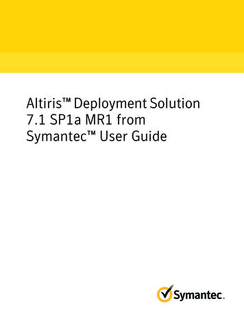
High Availability SSO Deployment Guide for Cisco Catalyst 9800 Series Wireless Controllers, Cisco IOSXE Amsterdam 17.1Platforms SupportedThere is no pre-empt functionality with SSO meaning that when the previous Active wireless controllerresumes operation, it will not take back the role as an Active wireless controller but will negotiate its statewith the current Active wireless controller and transition to Hot-Standby state.Platforms Supported Cisco Catalyst C9800-40 Wireless Controller Cisco Catalyst C9800-80 Wireless Controller Cisco Catalyst C9800-CL Wireless Controller Cisco Catalyst C9800-L Wireless ControllerSSO Pre-requisites HA Pair can only be form between two wireless controllers of the same form factor Both controllers must be running the same software version in order to form the HA Pair Maximum RP link latency 80 ms RTT, minimum bandwidth 60 Mbps and minimum MTU 1500SSO on Cisco Catalyst C9800-40-K9 and C9800-80-K9 WirelessControllersThe Cisco C9800-40-K9 wireless controller is an extensible and high performing wireless controller, whichcan scale up to 2000 access points and 32000 clients. The controller has four 10G data ports and athroughput of 40G.1RP— RJ-45 1G redundancy Ethernet port.2Gigabit SFP RP portThe Cisco C9800-80-K9 Wireless Controller is a 100G wireless controller that occupies two rack unitspace and supports a pluggable Module slot, and eight built-in 10GE/1GE interfaces.1RP— RJ-45 1G redundancy Ethernet port.25Gigabit SFP RP port
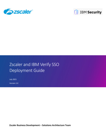
High Availability SSO Deployment Guide for Cisco Catalyst 9800 Series Wireless Controllers, Cisco IOSXE Amsterdam 17.1Physical Connectivity for C9800-L, C9800-40 and C9800-80 Wireless Controller HA SSOBoth C9800-40-K9 and C9800-80-K9 Wireless controllers have two RP Ports as shown in the figuresabove: RJ-45 Ethernet Redundancy port SFP Gigabit Redundancy PortIf both the Redundancy Ports are connected: SFP Gigabit Ethernet port takes precedence if they are connected at same time. HA between RJ-45 and SFP Gigabit RP ports is not supported. Only Cisco supported SFPs (GLC-LH-SMD and GLC-SX-MMD) are supported for RP port When HA link is up via RJ-45, SFPs on HA port should not be inserted even if there is no linkbetween them. As it is a physical level detection, this would cause the HA to go down asprecedence is given to SFPPhysical Connectivity for C9800-L, C9800-40 and C9800-80 WirelessController HA SSOThe HA Pair always has one active controller and one standby controller. If the active controller becomesunavailable, the standby assumes the role of the active. The Active wireless controller creates and updatesall the wireless information and constantly synchronizes that information with the standby controller. If theactive wireless controller fails, the standby wireless controller assumes the role of the active wirelesscontroller and continues to the keep the HA Pair operational. Access Points and clients continue to remainconnected during an active-to-standby switchover.Connecting C9800-L Wireless Controllers using RJ-45 RP Port for SSO6
High Availability SSO Deployment Guide for Cisco Catalyst 9800 Series Wireless Controllers, Cisco IOSXE Amsterdam 17.1Physical Connectivity for C9800-L, C9800-40 and C9800-80 Wireless Controller HA SSOConnecting C9800-40 and 9800-80 Wireless Controllers using RJ-45 RP Port forSSOConnecting C9800-40 and 9800-80 Wireless Controllers using SFP Gigabit RPPort for SSOConnecting a C9800 wireless controller HA pair to upstream switchesPrior to 17.1 following topologies were supported in terms of upstream connectivity to the network:1.SSO pair connected to upstream VSS pair with split links and RP connected back to back.2.SSO pair connected to upstream VSS pair with RP connected via the upstream set of switchesin order to detect gateway down scenario.3.SSO pair connected to upstream HSRP active and standby and RP connected via upstream setof switches in order to detect gateway down scenario.7
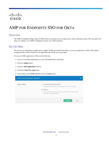
High Availability SSO Deployment Guide for Cisco Catalyst 9800 Series Wireless Controllers, Cisco IOSXE Amsterdam 17.1Physical Connectivity for C9800-L, C9800-40 and C9800-80 Wireless Controller HA SSOOption 1: Single VSS switch (or stack/VSL pair/modular switch) with RP backto-backSingle L2 port-channel on each box and enable dot1q to carry multiple VLANs. Spread the uplinks of theHA pair across the VSS pair and connect the RP back to back (no L2 network in between). Make sure thatswitch can scale in terms of ARP and MAC table entries.This is a recommended topology.Note: In HA SSO topology only LAG with mode ON is supported.8
High Availability SSO Deployment Guide for Cisco Catalyst 9800 Series Wireless Controllers, Cisco IOSXE Amsterdam 17.1Connecting a C9800 wireless controller HA pair to upstream switches with Release 17.1 and aboveOption 2: Single VSS switch (or stack/VSL pair/modular switch) with RP viaupstreamWith this topology a single L2 port-channel is created on each box. Enable dot1q to carry multiple VLANsand connect the standby in the same manner. Make sure that switch can scale in terms of ARP and MACtable entriesIMPORTANT: In this topology the links are not spread across the VSS stack. Connect RP port to the sameVSS/stack member as the uplinks and not back to backNote: In HA SSO topology only LAG with mode ON is supported.Option 3: Dual Distributed switches with HSRPWith this topology a single L2 port-channel is created on each box. Enable dot1q to carry multiple VLANsand connect the standby in the same manner. Make sure that switch can scale in terms of ARP and MACtable entries.IMPORTANT: Connect RP port to the same distribution switch as the uplinks and not back to backNote: In HA SSO topology only LAG with mode ON is supported prior to release 17.1. With 17.1, weadditionally support LACP and PAGP. See the LACP, PAGP support in SSO Pair section for more detailsConnecting a C9800 wireless controller HA pair to upstream switcheswith Release 17.1 and aboveWith the option of RMI and default gateway check feature available in release 17.1, the following topologiesare now supported and recommended:9
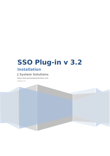
High Availability SSO Deployment Guide for Cisco Catalyst 9800 Series Wireless Controllers, Cisco IOSXE Amsterdam 17.1SSO on Cisco Catalyst C9800-CL running on ESXi, KVM, Hyper-V1.SSO pair connected to upstream VSS pair with split links and RP connected back to back.2.SSO pair connected to upstream VSS pair and RP connected back to back.3.SSO pair connected to upstream HSRP active and standby and RP connected back to back.SSO on Cisco Catalyst C9800-CL running on ESXi, KVM, Hyper-VThe Virtual Catalyst 9800 Wireless controller can be deployed as an HA Pair in a single or dual serversetup.The figure on the left shows Redundant port connected on the same server.The figure on the right shows Redundant port L2 connected to a separate server.Configuring High Availability SSO using GUIDevice redundancy can be configured from the Administration Device Redundancy pageOn the Active controller, the priority is set to a higher value than the standby controller. The wirelesscontroller with the higher priority value is selected as the active during the active-standby election process.The Remote IP is the IP address of the standby controller’s redundancy port IP.10
High Availability SSO Deployment Guide for Cisco Catalyst 9800 Series Wireless Controllers, Cisco IOSXE Amsterdam 17.1Configuring High Availability SSO using GUINote: This page has changed starting release 17.1 to include an option to configure the HA pair using RMI.Please refer to the Redundancy Management Interface section to see the updated screens forconfiguration.On the standby controller, the remote IP is set to the Active controller’s redundancy port IP1) Both IP address for the Local and Remote IP must be in the same subnet.2) It is suggested to use the 169.254.X.X/16 subnet. The last two octets can be derived from last twooctets of the management interface.3) Avoid using 10.10.10.x/24 subnet for the RP port due to defect in 9800 WLC.Clear Redundancy config clears the SSO configuration and returns the controller to standalone mode.Note: It is recommended to configure HA using the Redundancy Management Interface (RMI) startingRelease 17.1. To see configuration using RMI please see the Redundancy Management Interface section.11
High Availability SSO Deployment Guide for Cisco Catalyst 9800 Series Wireless Controllers, Cisco IOSXE Amsterdam 17.1Mobility MAC configurationMobility MAC configurationEnsure that you configure the mobility MAC address using the wireless mobility mac-address command forHigh-Availability to work.WLC (config)#wireless mobility mac-address ?H.H.H Enter Mac Address for the mobility messagesConfiguring High Availability SSO using CLI On Virtual Catalyst 9800 Wireless controller, enable High Availability SSO using the followingcommand on each of the two virtual Catalyst 9800 Wireless controller instanceschassis redundancy ha-interface RP interface local-ip local IP local IP subnet remote-ip remote IP e.g.On Virtual Catalyst 9800 Wireless controller instance-1:ipchassis redundancy ha-interface Gig 3 local-ip 172.23.174.85 /24 remote172.23.174.86On Virtual Catalyst 9800 Wireless controller instance-2:ip ipchassis redundancy ha-interface Gig 3 local-ip 172.23.174.86 /24 remote172.23.174.85On C9800-40 and C9800-80 wireless controller, enable High Availability SSO using the followingcommand on each of the two wireless controller unitschassis redundancy ha-interface local-ip local IP local IP subnet remote remote IP Reload both wireless controllers by executing the command reload from the CLINote: It is recommended to configure HA using the Redundancy Management Interface (RMI) startingRelease 17.1. To see configuration using RMI please see the Redundancy Management Interface section.Active and Standby Election ProcessAn active C9800 wireless controller retains its role as an Active Controller unless one of the followingevents occur: The wireless controller HA pair is reset. The active wireless controller is removed from the HA pair. The active wireless controller is reset or powered off. The active wireless controller fails.The active wireless controller is elected or re-elected based on one of these factors and in the order listedbelow:1.The wireless controller that is currently the active wireless controller.2.The wireless controller with the highest priority value.12
High Availability SSO Deployment Guide for Cisco Catalyst 9800 Series Wireless Controllers, Cisco IOSXE Amsterdam 17.1State Transition for HA SSO Pair formationNote: We recommend assigning the highest priority value to the wireless controller C9800 youprefer to be the active controller. A value of 2 would be the highest value and would be placedon the controller that you want to be the primary (since we only allow 1 or 2).Setting the Switch Priority Valuechassis chassis -number priority new-priority-numberChassis-number Specifies the chassis number and the new priority for the chassis. Thechassis number range is 1 to 2.The priority value range is 1-2 Examplewireless controller#chassis 1 priority 2You can display the current priority value by using the show chassis user EXEC command.The new priority value takes effect immediately but does not affect the current ActiveController. The new priority value helps determine which controller is elected as the newActive Controller when the current active wireless controller or HA redundant pair reloads.3.The wireless controller with the shortest start-up time.4.The wireless controller with the lowest MAC Address.The HA LED on the chassis can be used to identify the current Active Controller.State Transition for HA SSO Pair formation1.Active wireless controller in Non Redundant mode2.Standby Insertion for HA Pairing13
High Availability SSO Deployment Guide for Cisco Catalyst 9800 Series Wireless Controllers, Cisco IOSXE Amsterdam 17.1State Transition for HA SSO Pair formation3.HA Sync in Progress4.Terminal State for SSO14
High Availability SSO Deployment Guide for Cisco Catalyst 9800 Series Wireless Controllers, Cisco IOSXE Amsterdam 17.1Monitoring the HA PairNote: Breaking the HA Pair : The HA configuration can be disabled by using the chassis clear commandfollowed by a reloadMonitoring the HA PairBoth Active and Standby System can be monitored from the Management UI of the Active wirelesscontroller. This includes information about CPU and memory utilization as well and advanced CPU andmemory views.Navigate to Monitoring System Redundancy on the controller Web UI. The Redundancy States page is15
High Availability SSO Deployment Guide for Cisco Catalyst 9800 Series Wireless Controllers, Cisco IOSXE Amsterdam 17.1displayed:ParameterDescriptionShows the state of the active CPU controller module. Values are asfollows:ActiveStandby HOTMy StateDisableDisplays the state of the peer (or standby) CPU controller module.Values are as follows:Standby HOTPeer StateDisableDisplays the current state of the redundancy peer. Values are asfollows:Simplex— Single CPU controller module.ModeDuplex— Two CPU controller modules.Unit IDDisplays the unit ID of the CPU controller module.16
High Availability SSO Deployment Guide for Cisco Catalyst 9800 Series Wireless Controllers, Cisco IOSXE Amsterdam 17.1Redundancy Mode(Operational)Displays the current operational redundancy mode supported on theunit.Redundancy Mode(Configured)Displays the current configured redundancy mode supported on theunit.Displays the current functioning redundancy state of the unit. Valuesare as follows:SSORedundancy StateNot RedundantManual SwactDisplays whether manual switchovers have been enabled.CommunicationsDisplays whether communications are up or down between the twocontrollers.The same page displays Switchover history. The description for the following parameters are displayed inthe table below:ParameterDescriptionIndexDisplays the index number of the redundant unit.Previous ActiveDisplays the controller that was active prior to switchover.Current ActiveDisplays the controller that is currently active.Switch Over TimeDisplays the system time when the switchover occurred.Switch Over ReasonDisplays the cause of the switchover.Monitoring HA Pair from CLIThe command show chassis displays summary information about the HA Pair, including the MAC address, role, switch priority, and current state of each wireless controller in the redundant HA pair. By default, the Local MAC Address of the HA Pair is the MAC address of the first elected Active Controller.17
High Availability SSO Deployment Guide for Cisco Catalyst 9800 Series Wireless Controllers, Cisco IOSXE Amsterdam 17.1Verifying Redundancy StatesThe show chassis command points to the current C9800 wireless controller on the console using the(*) symbol against the chassis number as shown above.Verifying Redundancy States The command show redundancy can be used to monitor the state of the two unitswireless controller#show redundancy ?applicationbox 2 box application informationclientsRedundancy Facility (RF) client listconfig-syncShow Redundancy Config Sync statuscountersRedundancy Facility (RF) operational countersdomainSpecify the RF domainhistoryRedundancy Facility (RF) historyidb-sync-history Redundancy Facility (RF) IDB sync historylinecard-groupLine card redundancy group informationriiDisplay the redundancy interface identifier for Box to BoxstatesRedundancy Facility (RF) statesswitchoverRedundancy Facility (RF) switchovertraceRedundancy Facility (RF) trace Output modifiers cr cr The command show redundancy displays the redundant system and the current processorinformation. The redundant system information includes the system uptime, standby failures,switchover reason, hardware mode, and configured and operating redundancy mode. The currentprocessor information displayed includes the image version, active location, software state, BOOTvariable, configuration register value, and uptime in the current state, and so on. The PeerProcessor information is only available from the Active Controller.18
High Availability SSO Deployment Guide for Cisco Catalyst 9800 Series Wireless Controllers, Cisco IOSXE Amsterdam 17.1Verifying Redundancy States The command show redundancy states displays all the redundancy states of the active and standbycontrollers. Manual Switchover Action (Manual Swact) i.e. the command redundancy force-switchover cannotbe executed on the Standby wireless controller and is enabled only on the Active Controller.19
High Availability SSO Deployment Guide for Cisco Catalyst 9800 Series Wireless Controllers, Cisco IOSXE Amsterdam 17.1Accessing standby wireless controller console Switchover History can be viewed using the following commandAccessing standby wireless controller consoleThe active controller can be accessed through a console connection, Telnet, an SSH, or a Web Browser byusing the Management IP address. To use the console on the standby wireless controller, executethe following commands from the active Catalyst 9800 Wireless controllerconf tredundancymain-cpustandby console enableThe prompt on the Standby console is appended with “-stby” to reflect the Standby wireless controllerconsole as shown below.Note: The show chassis command points to the current C9800 wireless controller on the console using the (*) symbol against the chassis number as shown above. In this case it is the console of the standbyUnit.20
High Availability SSO Deployment Guide for Cisco Catalyst 9800 Series Wireless Controllers, Cisco IOSXE Amsterdam 17.1Switchover FunctionalitySwitchover FunctionalityProcess Failure SwitchoverThis type of switch over occurs when any of the key processes running on the Active unit fails or crashes.Upon such a failure, the Active unit reloads and the hot Standby takes over and becomes the new Activeunit. When the failed system boots up, it will transition to Hot-Standby state. If the Standby unit is not yet inHot Standby State, both units are reloaded and there will be no SSO. A process failure on the standby (hotor not) will cause it to reload.Power-fail SwitchoverThis switchover from the Active to Standby unit is caused due to power failure of the current Active unit.The current Standby unit becomes the new Active unit and when the failed system boots up, it willtransition to Hot-Standby state.Manual SwitchoverThis is a user initiated forced switchover between the Active and Standby unit. The current Standby unitbecomes the new Active unit and when the failed system boots up, it will transition to Hot-Standby state.To perform a manual switchover, execute the redundancy force-switchover command. This commandinitiates a graceful switchover from the active to the standby controller. The active controller reloads andthe standby takes over as the New Active controller.21
High Availability SSO Deployment Guide for Cisco Catalyst 9800 Series Wireless Controllers, Cisco IOSXE Amsterdam 17.1Failover ProcessFailover ProcessActive wireless controllerStandby wireless controllerAn Access
SSO on Cisco Catalyst C9800-40-K9 and C9800-80-K9 Wireless Controllers The Cisco C9800-40-K9 wireless controller is an extensible and high performing wireless controller, which can scale up to 2000 access points and 32000 clients. The controller has four 10G data ports and a