Transcription
Cisco UCS Servers RAID GuideJune 19, 2013Americas HeadquartersCisco Systems, Inc.170 West Tasman DriveSan Jose, CA 95134-1706USAhttp://www.cisco.comTel: 408 526-4000800 553-NETS (6387)Fax: 408 527-0883Text Part Number: OL-26591-01
THE SPECIFICATIONS AND INFORMATION REGARDING THE PRODUCTS IN THIS MANUAL ARE SUBJECT TO CHANGE WITHOUT NOTICE. ALLSTATEMENTS, INFORMATION, AND RECOMMENDATIONS IN THIS MANUAL ARE BELIEVED TO BE ACCURATE BUT ARE PRESENTED WITHOUTWARRANTY OF ANY KIND, EXPRESS OR IMPLIED. USERS MUST TAKE FULL RESPONSIBILITY FOR THEIR APPLICATION OF ANY PRODUCTS.THE SOFTWARE LICENSE AND LIMITED WARRANTY FOR THE ACCOMPANYING PRODUCT ARE SET FORTH IN THE INFORMATION PACKET THATSHIPPED WITH THE PRODUCT AND ARE INCORPORATED HEREIN BY THIS REFERENCE. IF YOU ARE UNABLE TO LOCATE THE SOFTWARE LICENSEOR LIMITED WARRANTY, CONTACT YOUR CISCO REPRESENTATIVE FOR A COPY.The following information is for FCC compliance of Class A devices: This equipment has been tested and found to comply with the limits for a Class A digital device, pursuantto part 15 of the FCC rules. These limits are designed to provide reasonable protection against harmful interference when the equipment is operated in a commercialenvironment. This equipment generates, uses, and can radiate radio-frequency energy and, if not installed and used in accordance with the instruction manual, may causeharmful interference to radio communications. Operation of this equipment in a residential area is likely to cause harmful interference, in which case users will be requiredto correct the interference at their own expense.The following information is for FCC compliance of Class B devices: This equipment has been tested and found to comply with the limits for a Class B digital device, pursuantto part 15 of the FCC rules. These limits are designed to provide reasonable protection against harmful interference in a residential installation. This equipment generates,uses and can radiate radio frequency energy and, if not installed and used in accordance with the instructions, may cause harmful interference to radio communications.However, there is no guarantee that interference will not occur in a particular installation. If the equipment causes interference to radio or television reception, which can bedetermined by turning the equipment off and on, users are encouraged to try to correct the interference by using one or more of the following measures: Reorient or relocate the receiving antenna.Increase the separation between the equipment and receiver.Connect the equipment into an outlet on a circuit different from that to which the receiver is connected.Consult the dealer or an experienced radio/TV technician for help.Modifications to this product not authorized by Cisco could void the FCC approval and negate your authority to operate the product.The Cisco implementation of TCP header compression is an adaptation of a program developed by the University of California, Berkeley (UCB) as part of UCB’s publicdomain version of the UNIX operating system. All rights reserved. Copyright 1981, Regents of the University of California.NOTWITHSTANDING ANY OTHER WARRANTY HEREIN, ALL DOCUMENT FILES AND SOFTWARE OF THESE SUPPLIERS ARE PROVIDED “AS IS” WITHALL FAULTS. CISCO AND THE ABOVE-NAMED SUPPLIERS DISCLAIM ALL WARRANTIES, EXPRESSED OR IMPLIED, INCLUDING, WITHOUTLIMITATION, THOSE OF MERCHANTABILITY, FITNESS FOR A PARTICULAR PURPOSE AND NONINFRINGEMENT OR ARISING FROM A COURSE OFDEALING, USAGE, OR TRADE PRACTICE.IN NO EVENT SHALL CISCO OR ITS SUPPLIERS BE LIABLE FOR ANY INDIRECT, SPECIAL, CONSEQUENTIAL, OR INCIDENTAL DAMAGES, INCLUDING,WITHOUT LIMITATION, LOST PROFITS OR LOSS OR DAMAGE TO DATA ARISING OUT OF THE USE OR INABILITY TO USE THIS MANUAL, EVEN IF CISCOOR ITS SUPPLIERS HAVE BEEN ADVISED OF THE POSSIBILITY OF SUCH DAMAGES.Cisco and the Cisco logo are trademarks or registered trademarks of Cisco and/or its affiliates in the U.S. and other countries. To view a list of Cisco trademarks, go to thisURL: www.cisco.com/go/trademarks. Third-party trademarks mentioned are the property of their respective owners. The use of the word partner does not imply a partnershiprelationship between Cisco and any other company. (1110R)Any Internet Protocol (IP) addresses and phone numbers used in this document are not intended to be actual addresses and phone numbers. Any examples, command displayoutput, network topology diagrams, and other figures included in the document are shown for illustrative purposes only. Any use of actual IP addresses or phone numbers inillustrative content is unintentional and coincidental.Cisco UCS Servers RAID Guide 2013 Cisco Systems, Inc. All rights reserved.
Related DocumentationixObtaining Documentation and Submitting a Service RequestCHAPTER1RAID Overviewix1-1Information About RAID 1-1Drive Group 1-1Virtual Drive 1-1Disk Striping 1-2Disk Mirroring (RAID 1 and RAID 10)Parity 1-3Disk Spanning 1-3Hot Spares 1-4Global Hot Spare 1-5Dedicated Hot Spare 1-5Disk Rebuilds 1-6Hot Swap 1-6Drive States 1-7Virtual Drive States 1-7RAID Levels 1-7RAID Levels SummaryRAID 0 1-8RAID 1 1-9RAID 5 1-10RAID 6 1-11RAID 00 1-12RAID 10 1-13RAID 50 1-14RAID 60 1-15Fault Tolerance 1-161-21-8Generic Drive Replacement Procedure 1-17Removing a Drive from a Server 1-17Cisco UCS Servers RAID GuideOL-26591-01iii
ContentsInstalling a Drive in a Server1-18Platform-Specific RAID and Drive ProceduresCHAPTER21-18Using Cisco Integrated Management Controller and Cisco UCS Server Configuration Utility forRAID Monitoring and Configuring 2-1Cisco Integrated Management Controller—Viewing Storage PropertiesCisco UCS Server Configuration Utility—RAID Configuration 2-2CHAPTER3Using Cisco UCS Manager for RAID Configuring and Monitoring2-13-1Cisco UCS Manager Configuration 3-1Local Disk Configuration Policy 3-1Guidelines for all Local Disk Configuration Policies 3-2Guidelines for Local Disk Configuration Policies Configured for RAIDCreating a Local Disk Configuration Policy 3-4Changing a Local Disk Configuration Policy 3-6Deleting a Local Disk Configuration Policy 3-7Server Disk Drive Monitoring 3-7Support for Disk Drive Monitoring 3-7Viewing the Status of a Disk Drive 3-8Interpreting the Status of a Monitored Disk Drive3-33-9RAID Controllers in UCS Servers 3-10Determining Which Controller is in Your Server 3-11RAID Controllers 3-12Disabling Quiet Boot 3-12Accessing ROM-Based Controller Utilities 3-13Documentation About RAID Controllers and LSI Utilities 3-13Moving a RAID Cluster Using UCS Software Version 1.4(1) 3-13Moving a RAID Cluster Using UCS Software Version 1.4(2) and Later ReleasesMoving a RAID Cluster Between B200 M3 Servers 3-15Replacing a Failed Drive in a RAID Cluster 3-16CHAPTER4Configuring the LSI SAS2 Integrated RAID ControllerInformation about LSI Integrated RAID4-14-1Mirrored Volumes 4-2Operation of Mirrored Volumes 4-3Mirrored Volume Features 4-6Mirroring and Mirroring Enhanced FeaturesIntegrated Striping 4-8Integrated Striping Features3-144-74-9Cisco UCS Servers RAID GuideivOL-26591-01
ContentsCreating Mirrored Volumes 4-10Launching the LSI SAS2 BIOS Configuration Utility 4-10Creating Mirrored Volumes 4-11Creating an Integrated Mirroring Volume 4-11Creating an Integrated Mirroring Enhanced or Integrated Mirroring and Striping VolumeExpanding an Integrated Mirroring Volume with OCE 4-14Managing Hot Spare Disks 4-15Creating Hot Spare Disks 4-15Deleting Hot Spare Disks 4-15Other Configuration Tasks 4-16Viewing Volume Properties 4-16Running a Consistency Check 4-16Activating an Array 4-17Deleting an Array 4-17Locating Disk Drives in a Volume 4-18Choosing a Boot Disk 4-184-13Creating Integrated Striping Volumes 4-19Other Configuration Tasks 4-21Viewing Volume Properties 4-21Activating an Array 4-21Deleting an Array 4-21Locating Disk Drives in a Volume 4-22Choosing a Boot Disk 4-23Determining Which Controller is in Your Server4-23Disabling Quiet Boot for CIMC Firmware Earlier than Release 1.2(1)Launching Option ROM-Based Controller Utilities4-24Restoring RAID Configuration After Replacing a RAID ControllerCHAPTER5LSI MegaRAID SAS Controller Tasks4-244-255-1LSI MegaRAID Controller Management UtilitiesLSI WebBIOS Configuration Utility 5-1MegaRAID Command Tool 5-1MegaRAID Storage Manager 5-25-1LSI WebBIOS CU 5-2Starting the WebBIOS CU 5-2WebBIOS CU Main Menu Window Options 5-3Toolbar 5-4Menu Options 5-4Configuring RAID Drive Groups and Virtual Drives5-5Cisco UCS Servers RAID GuideOL-26591-01v
ContentsChoosing the Configuration with the Configuration Wizard 5-5Using Automatic Configuration 5-5Using Manual Configuration 5-6Viewing and Changing Device Properties 5-11Viewing Controller Properties 5-11Viewing Virtual Drive Properties, Policies, and Operations 5-13Viewing Physical Drive Properties and Operations 5-14Viewing and Changing Battery Backup Unit Information 5-15Managing RAID 5-16Expanding a Virtual Drive 5-16Monitoring Array Health 5-16Recovery 5-17Deleting a Virtual Drive 5-18Migrating an Array to a New Server 5-18Foreign Configurations in Cable Pull and Drive Removal Scenarios 5-19Importing Foreign Configurations from Integrated RAID to MegaRAID 5-20Troubleshooting Information 5-20Migrating the RAID Level of a Virtual Drive 5-20Determining Which Controller is in Your Server 5-21Disabling Quiet Boot for CIMC Firmware Earlier than Release 1.2(1)Launching an Option ROM-Based Controller Utility 5-22LSI MegaRAID Card Beep Codes 5-23Restoring the RAID Configuration After Replacing a RAID ControllerCHAPTER6Configuring the Embedded ICH10R SATA Controller5-225-236-1Enabling the Integrated Intel ICH10R RAID Controller in the BIOSLaunching the LSI Software RAID Setup Utility 6-16-1Configuring the Onboard Intel ICH10R RAID Controller 6-2Creating a New RAID Configuration 6-3Viewing or Changing a RAID Configuration 6-4Cisco UCS Servers RAID GuideviOL-26591-01
PrefaceThis preface describes the organization of the Cisco UCS C-Series Servers RAID Configuration Guide.It also provides information on how to obtain related documentation and submit a service request.OrganizationThis guide is organized as into the following chapters:ChapterTitleDescriptionChapter 1RAID OverviewDescribes Redundant Array of Independent Disks(RAID), RAID functions and benefits, RAIDcomponents, RAID levels, and configuration strategies.It also describes RAID availability and offers tips forconfiguration planning.Chapter 2Using Cisco IntegratedManagement Controller andCisco UCS ServerConfiguration Utility forRAID Monitoring andConfiguringSummarizes monitoring and configuring RAIDcontrollers using Cisco Integrated ManagementController (CIMC) and Cisco UCS ServerConfiguration Utility (UCS-SCU).Chapter 3Using Cisco UCS Manager for Summarizes monitoring and configuring RAIDcontrollers using Cisco UCS Manager.RAID Configuring andMonitoringChapter 4Configuring the LSI SAS2Integrated RAID ControllerProvides an introduction to the features and benefits ofthe LSI Integrated RAID solution for LSI SAS2 RAIDcontrollers.Chapter 5LSI MegaRAID SASController TasksDescribes the LSI WebBIOS Configuration Utility(CU) and describes creating and managing RAIDconfigurations on LSI MegaRAID SAS controllers.Chapter 6Configuring the EmbeddedICH10R SATA ControllerDescribes how to use the LSI Software RAID setupUtility to configure the onboard Intel ICH10R RAIDcontroller.Cisco UCS Servers RAID GuideOL-26591-01vii
PrefaceConventionsConventionsThis document uses the following conventions:ConventionIndicationbold fontCommands and keywords and user-entered text appear in bold font.italic fontDocument titles, new or emphasized terms, and arguments for which you supplyvalues are in italic font.[ ]Elements in square brackets are optional.{x y z }Required alternative keywords are grouped in braces and separated byvertical bars.[x y z]Optional alternative keywords are grouped in brackets and separated byvertical bars.stringA nonquoted set of characters. Do not use quotation marks around the string orthe string will include the quotation marks.courierfontTerminal sessions and information the system displays appear in courier font. Non-printing characters such as passwords are in angle brackets.[ ]Default responses to system prompts are in square brackets.!, #An exclamation point (!) or a pound sign (#) at the beginning of a line of codeindicates a comment line.NoteMeans reader take note.TipMeans the following information will help you solve a problem.CautionTimesaverWarningMeans reader be careful. In this situation, you might perform an action that could result in equipmentdamage or loss of data.Means the described action saves time. You can save time by performing the action described inthe paragraph.Means reader be warned. In this situation, you might perform an action that could result inbodily injury.Cisco UCS Servers RAID GuideviiiOL-26591-01
PrefaceConventionsRelated DocumentationThe documentation set for the Cisco Unified Computing System (UCS) C-Series rack-mount servers isdescribed in the roadmap document at the following link:Cisco UCS C-Series Documentation RoadmapObtaining Documentation and Submitting a Service RequestFor information on obtaining documentation, submitting a service request, and gathering additionalinformation, see the monthly What’s New in Cisco Product Documentation, which also lists all new andrevised Cisco technical documentation, w/whatsnew.htmlSubscribe to the What’s New in Cisco Product Documentation as an RSS feed and set content to bedelivered directly to your desktop using a reader application. The RSS feeds are a free service. Cisco currentlysupports RSS Version 2.0.Cisco UCS Servers RAID GuideOL-26591-01ix
PrefaceConventionsCisco UCS Servers RAID GuidexOL-26591-01
CH A P T E R1RAID OverviewThis chapter describes RAID (Redundant Array of Independent Disks), RAID functions and benefits,RAID components, RAID levels, and configuration strategies.This chapter contains the following sections: Information About RAID, page 1-1 RAID Levels, page 1-7 Generic Drive Replacement Procedure, page 1-17 Platform-Specific RAID and Drive Procedures, page 1-18Information About RAIDRAID is an array, or group, of multiple independent physical drives that provide high performance andfault tolerance. A RAID drive group improves input/output (I/O) performance and reliability. The RAIDdrive group appears to the host computer as a single storage unit or as multiple virtual units. I/O isexpedited because several drives can be accessed simultaneously.RAID drive groups improve data storage reliability and fault tolerance compared to single-drive storagesystems. Data loss resulting from a drive failure can be prevented by reconstructing missing data fromthe remaining drives. RAID improves I/O performance and increases storage subsystem reliability.RAID levels describe a system for ensuring the availability and redundancy of data stored on large disksubsystems. See RAID Levels, page 1-7 for detailed information about RAID levels. The RAIDdrive-group components and RAID levels are described in the following sections.Drive GroupA drive group is a group of physical drives. These drives are managed in partitions known as virtualdrives.Virtual DriveA virtual drive is a partition in a drive group that is made up of contiguous data segments on the drives.A virtual drive can consist of an entire drive group, more than one entire drive group, a part of a drivegroup, parts of more than one drive group, or a combination of any two of these conditions.Cisco UCS Servers RAID GuideOL-26591-011-1
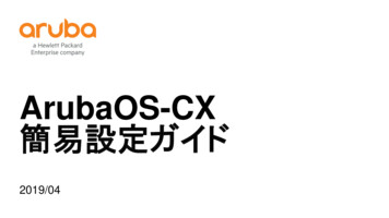
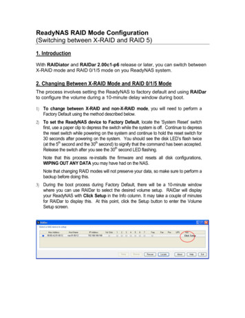
Chapter 1RAID OverviewInformation About RAIDDisk StripingDisk striping (used in RAID level 0) allows you to write data across multiple drives instead of only onedrive. Disk striping involves partitioning each drive storage space into stripes that can vary in size from8 KB to 1024 KB. These stripes are interleaved in a repeated sequential manner. The combined storagespace is composed of stripes from each drive. We recommend that you keep stripe sizes the same acrossRAID drive groups.For example, in a four-disk system using only disk striping, segment 1 is written to disk 1, segment 2 iswritten to disk 2, and so on (see Figure 1-1). Disk striping enhances performance because multiple drivesare accessed simultaneously, but disk striping does not provide data redundancySegment 1Segment 5Segment 9Example of Disk Striping (RAID 0)Segment 2Segment 6Segment 10Segment 3Segment 7Segment 11Segment 4Segment 8Segment 12332084Figure 1-1Stripe width is the number of drives involved in a drive group where striping is implemented. Forexample, a four-disk drive group with disk striping has a stripe width of four.The stripe size is the length of the interleaved data segments that the RAID controller writes acrossmultiple drives, not including parity drives. For example, consider a stripe that contains 64 KB of diskspace and has 16 KB of data residing on each disk in the stripe. In this case, the stripe size is 64 KB andthe strip size is 16 KB.The strip size is the portion of a stripe that resides on a single drive.Disk Mirroring (RAID 1 and RAID 10)With disk mirroring (used in RAID 1 and RAID 10), data written to one drive is simultaneously writtento another drive. The primary advantage of disk mirroring is that it provides 100 percent dataredundancy. Because the contents of the disk are completely written to a second disk, data is not lost ifone disk fails. In addition, both drives contain the same data at all times, so either disk can act as theoperational disk. If one disk fails, the contents of the other disk can be used to run the system andreconstruct the failed disk.Disk mirroring provides 100 percent redundancy but is expensive because each drive in the system mustbe duplicated (see Figure 1-2).Cisco UCS Servers RAID Guide1-2OL-26591-01
Chapter 1RAID OverviewInformation About RAIDSegment 1Segment 2Segment 3Segment 4Example of Disk Mirroring (RAID 1)Segment 1 DuplicatedSegment 2 DuplicatedSegment 3 DuplicatedSegment 4 Duplicated332085Figure 1-2ParityParity generates a set of redundancy data from two or more parent data sets. The redundancy data canbe used to reconstruct one of the parent data sets in the event of a drive failure. Parity data does not fullyduplicate the parent data sets, but parity generation can slow the write process. In RAID, this method isapplied to entire drives or stripes across all of the drives in a drive group. There are two types of parity: Dedicated parity—The parity data on two or more drives is stored on an additional disk. Distributed parity—The parity data is distributed across more than one drive in the system.RAID 5 combines distributed parity with disk striping (see Figure 1-3). If a single drive fails, it can berebuilt from the parity and the data on the remaining drives. RAID 5 uses parity to provide redundancyfor one drive failure without duplicating the contents of entire drives. RAID 6 uses distributed parity anddisk striping also but adds a second set of parity data so that it can survive up to two drive failures.Parity is distributed across all drives in the drive group.Figure 1-3Example of Distributed Parity (RAID 5)Segment 1Segment 7Segment 2Segment 8Segment 3Segment 9Segment 4Segment 10Segment 13Segment 19Segment 25Parity (26–30)Segment 14Segment 20Parity (21–25)Segment 26Segment 15Parity (16–20)Segment 21Segment 27Parity (11–15)Segment 16Segment 22Segment 28Segment 5Parity (6–10)Segment 11Segment 17Segment 23Segment 29Parity (1–5)Segment 6Segment 12Segment 18Segment 24Segment 30332086NoteDisk SpanningDisk spanning allows multiple drives to function like one big drive. Spanning overcomes lack of diskspace and simplifies storage management by combining existing resources or adding relativelyinexpensive resources. For example, four 20-GB drives can be combined to appear to the operatingsystem as a single 80-GB drive.Cisco UCS Servers RAID GuideOL-26591-011-3
Chapter 1RAID OverviewInformation About RAIDSpanning alone does not provide reliability or performance enhancements. Spanned virtual drives musthave the same stripe size and must be contiguous. In Figure 1-4, RAID 1 drive groups are turned into aRAID 10 drive group.Make sure that the spans are in different backplanes, so that if one span fails, you do not lose the wholedrive group.Figure 1-4Example of Disk Spanning60 GB60 GBCan be accessed asone 120-GB drive60 GB60 GBCan be accessed asone 120-GB drive332087NoteSpanning two contiguous RAID 0 virtual drives does not produce a new RAID level or add faulttolerance. It does increase the capacity of the virtual drive and improves performance by doubling thenumber of physical disks.Table 1-1 describes how to configure RAID 00, RAID 10, RAID 50, and RAID 60 by spanning. Thevirtual drives must have the same stripe size and the maximum number of spans is eight. The full drivecapacity is used when you span virtual drives; you cannot specify a smaller drive capacity.Table 1-1Spanning for RAID 00, RAID 10, RAID 50, and RAID 60RAIDLevel Description00Configure RAID 00 by spanning two contiguous RAID 0 virtual drives, up to the maximumnumber of supported devices for the controller.10Configure RAID 10 by spanning two contiguous RAID 1 virtual drives, up to the maximumnumber of supported devices for the controller.RAID 10 supports a maximum of eight spans. You must use an even number of drives in eachRAID virtual drive in the span.The RAID 1 virtual drives must have the same stripe size.50Configure RAID 50 by spanning two contiguous RAID 5 virtual drives.The RAID 5 virtual drives must have the same stripe size.60Configure RAID 60 by spanning two contiguous RAID 6 virtual drives.The RAID 6 virtual drives must have the same stripe size.Hot SparesA hot spare is an extra, unused drive that is part of the disk subsystem. It is usually in standby mode,ready for service if a drive fails. If a drive used in a RAID virtual drive fails, a hot spare automaticallytakes its place and the data on the failed drive is rebuilt on the hot spare. Hot spares can be used for RAIDlevels 1, 5, 6, 10, 50, and 60.Cisco UCS Servers RAID Guide1-4OL-26591-01
Chapter 1RAID OverviewInformation About RAIDHot spares permit you to replace failed drives without system shutdown or user intervention. MegaRAIDSAS RAID controllers can implement automatic and transparent rebuilds of failed drives using hot sparedrives, providing a high degree of fault tolerance and zero downtime.NoteWhen running RAID 0 and RAID 5 virtual drives on the same set of drives (a sliced configuration), arebuild to a hot spare cannot occur after a drive failure until the RAID 0 virtual drive is deleted.The LSI RAID management software allows you to specify drives as hot spares. When a hot spare isneeded, the RAID controller assigns the hot spare that has a capacity closest to and at least as great asthat of the failed drive to take the place of the failed drive. The failed drive is removed from the virtualdrive and marked ready awaiting removal once the rebuild to a hot spare begins. You can make hot sparesof the drives that are not in a RAID virtual drive.You can use the RAID management software to designate the hot spare to have enclosure affinity, whichmeans that if drive failures are present on a split backplane configuration, the hot spare is used first onthe backplane side that it resides in.If the hot spare is designated as having enclosure affinity, it attempts to rebuild any failed drives on thebackplane that it resides in before rebuilding any other drives on other backplanes.NoteIf a rebuild to a hot spare fails for any reason, the hot spare drive is marked as failed. If the source drivefails, both the source drive and the hot spare drive is marked as failed.There are two types of hot spares: Global hot spare Dedicated hot spareGlobal Hot SpareA global hot spare drive can be used to replace any failed drive in a redundant drive group as long as itscapacity is equal to or larger than the capacity of the failed drive. A global hot spare defined on anychannel should be available to replace a failed drive on both channels.Dedicated Hot SpareA dedicated hot spare can be used to replace a failed drive only in a chosen drive group. One or moredrives can be designated as a member of a spare drive pool. The most suitable drive from the pool ischosen for failover. A dedicated hot spare is used before one from the global hot spare pool.Hot spare drives can be located on any RAID channel. Standby hot spares (not being used in RAID drivegroup) are polled every 60 seconds at a minimum, and their status is made available in the drive groupmanagement software. RAID controllers offer the ability to rebuild with a disk that is in a system, butnot initially set to be a hot spare.When using hot spares, observe the following guidelines: Hot spares are used only in drive groups with redundancy, which includes RAID levels 1, 5, 6, 10,50, and 60. A hot spare connected to a specific RAID controller can be used to rebuild a drive that is connectedto the same controller only.Cisco UCS Servers RAID GuideOL-26591-011-5
Chapter 1RAID OverviewInformation About RAID You must assign the hot spare to one or more drives through the controller BIOS or use drive groupmanagement software to place it in the hot spare pool. A hot spare must have free space equal to or greater than the drive it replaces. For example, toreplace an 18-GB drive, the hot spare must be 18 GB or larger.Disk RebuildsWhen a drive in a RAID drive group fails, you can rebuild the drive by recreating the data that was storedon the drive before it failed. The RAID controller recreates the data using the data stored on the otherdrives in the drive group. Rebuilding can be done only in drive groups with data redundancy, whichincludes RAID 1, 5, 6, 10, 50, and 60 drive groups.The RAID controller uses hot spares to rebuild failed drives automatically and transparently, atuser-defined rebuild rates. If a hot spare is available, the rebuild can start automatically when a drivefails. If a hot spare is not available, the failed drive must be replaced with a new drive so that the data onthe failed drive can be rebuilt.The failed drive is removed from the virtual drive and marked ready awaiting removal when the rebuildto a hot spare begins. If the system goes down during a rebuild, the RAID controller automaticallyrestarts the rebuild after the system reboots.NoteWhen the rebuild to a hot spare begins, the failed drive is often removed from the virtual drive beforemanagement applications detect the failed drive. When this situation occurs, the events logs show thedrive rebuilding to the hot spare without showing the failed drive. The formerly failed drive is markedas ready after a rebuild begins to a hot spare.NoteIf a source drive fails during a rebuild to a hot spare, the rebuild fails, and the failed source drive ismarked as offline. In addition, the rebuilding hot spare drive is changed back to a hot spare. After arebuild fails because of a source drive failure, the dedicated hot spare is still dedicated and assigned tothe correct drive group, and the global hot spare is still global.An automatic drive rebuild does not start if you replace a drive during a RAID-level migration. Therebuild must be started manually after the expansion or migration procedure is complete. (RAID-levelmigration changes a virtual drive from one RAID level to another.)Hot SwapA hot swap is the manual replacement of a defective drive unit while the computer is still running(performing its normal functions). When a new drive is installed, a rebuild occurs automatically if oneof the following happens: The newly inserted drive is the same capacity as or larger than the failed drive. It is placed in the same drive bay as the failed drive it is replacing.The RAID controller can be configured to detect the new drives and rebuild the contents of the driveautomatically. The backplane and enclosure must support hot swap for the functionality to work.Cisco UCS Servers RAID Guide1-6OL-26591-01
Chapter 1RAID OverviewRAID LevelsDrive StatesA drive state is a property that indicates the status of the drive. Table 1-2 describes the drive states.Table 1-2Drive StatesStateDescriptionOnlineA drive that can be accessed by the RAID controller and is part of the virtual drive.UnconfiguredGoodA drive that is functioning normally but is not configured as a part of a virtual driveor as a hot spare.Hot SpareA drive that is powered up and ready for use as a spare in case an online drive fails.FailedA drive that was originally configured as Online or Hot Spare but on which thefirmware detects an unrecoverable error.RebuildA drive to which data is being written to restore full redundancy for a virtual drive.UnconfiguredBadA drive on which the firmware detects an unrecoverable error; the drive wasUnconfigured Good or the drive could not be initialized.MissingA drive that was Online but which has been removed from its location.OfflineA drive that is part of a virtual drive but which has invalid data as far as the RAIDconfiguration is concerned.When a virtual drive with cached data goes offline, the cache for the virtual drive isdiscarded. Because the virtual drive is offline, the cache cannot be saved.Virtual Drive StatesA virtual drive state is a property indicating the status of the virtual drive. Table 1-3 describes the virtualdrive states.Table 1-3Virtual Drive StatesStateDescriptionOptimalThe virtual drive operating condition is good. All configured drives are online.DegradedThe virtual drive operating condition is not optimal. One of the configured drives hasfailed or is offline.PartialDegradedThe operating condition in a RAID 6 virtual drive is not optimal. One of theconfigured drives has failed or is offline. RAID 6 can tolerate up to two drive failures
RAID 0 1-8 RAID 1 1-9 RAID 5 1-10 RAID 6 1-11 RAID 00 1-12 RAID 10 1-13 RAID 50 1-14 RAID 60 1-15 Fault Tolerance 1-16 Generic Drive Replacement Procedure 1-17 Removing a Drive from a Server 1-17. Contents iv Cisco UCS Servers RAID Guide OL-26591-01 Installing a Drive in a .