Transcription
Voltage/current dividersVoltage and current dividers are easy to understand and use. They are soeasy that it may seem not worth the bother of learning them as aseparate techniques. But the divider methods, when combined with theequivalent resistances, may be the most used technique in electronics.Knowing how to use dividers will allow us to quickly recognize what ishappening in a circuit and determine important voltages and currents.An engineer could certainly analyze and design circuits without havingvoltage and dividers in their “tool bag”, but they would be wasting lotsof time writing unnecessary KVL and KCL equations.G. Tuttle – 2022voltage/current dividers – 1
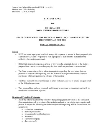
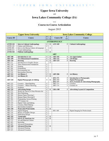
Voltage dividerConsider a portion of circuit thathas several resistors in series, likethe circuit at right. Suppose wewant to nd the voltage across R2. vR1 –iSVS –R1R2R3 vR2–– vR3 We could start by nding the current, which would be equal to thesource voltage divided by the equivalent resistance of the string.VSiS ReqFor the series string, Req R1 R2 R3.Then the voltage across R2 is justR2R2vR2 R2 iS VS VSReqR1 R2 R3The total voltage is divided among the resistor in the string. The fractionof the voltage across R2 is given by a simple resistor ratio.voltage/current dividers – 2fifiG. Tuttle – 2022
The other resistor voltages are calculated just as easily. vR1 –iSVS –R1R2R3– vR3 vR2–R2vR2 VSR1 R2 R3R3vR3 VSR1 R2 R3The three divided voltages sum up to VS, as KVL insists. If we insertsome numbers: VS 15 V, R1 4.7 kΩ, R2 15 kΩ, and R3 10 kΩ.4.7 kΩvR1 (15 V) 2.37 V4.7 kΩ 15 kΩ 10 kΩ15 kΩvR2 (15 V) 7.58 V4.7 kΩ 15 kΩ 10 kΩIt’s that easy.10 kΩvR3 (15 V) 5.05 V4.7 kΩ 15 kΩ 10 kΩG. Tuttle – 2022voltage/current dividers – 3
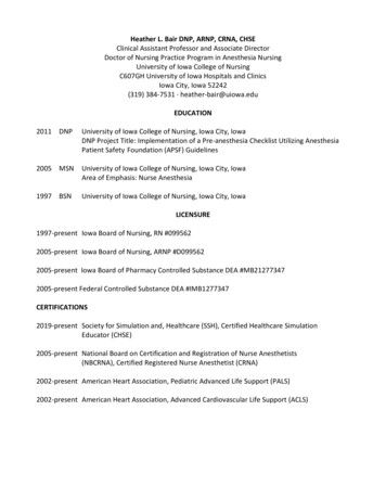
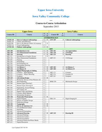
Current dividerSame idea, but with parallelresistors dividing a current.Suppose we want to know thecurrent through R2. vS R1–ISR2iR1R3iR2iR3We could start by nding the voltage, which would be equal to the sourcecurrent multiplied by the equivalent resistance of the parallel resistors.vS IS ReqFor the parallel combination, Req 1R11 1R2 1R3Then the current through R2 isReqvSiR2 IS R2R21R11R2 1R2 1R3 ISAs in the case of the voltage divider, the fraction of the current throughone resistor is determined by a simple ratio based on resistor values. Butin the current case, resistor inverses are used.voltage/current dividers – 4fiG. Tuttle – 2022
The other resistor currents are calculated just as easily. vS R1–ISiR1 R2iR1R3iR2iR3iR3 1R11R11R1 1R21R31R2 1R3 1R3 IS ISThe three divided currents sum up to IS, as KCL insists. If we insert somenumbers: IS 15 mA, R1 2.2 kΩ, R2 3.3 kΩ, and R3 6.8 kΩ.iR1 iR2 iR3 G. Tuttle – 202212.2 kΩ12.2 kΩ12.2 kΩ 12.2 kΩ13.3 kΩ 13.3 kΩ13.3 kΩ 16.8 kΩ13.3 kΩ 16.8 kΩ 16.8 kΩ 16.8 kΩ(15 mA) 7.54 mA(15 mA) 5.02 mA(15 mA) 2.44 mAvoltage/current dividers – 5
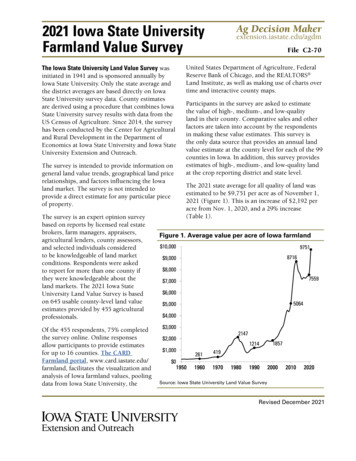
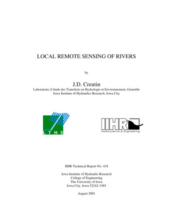
In many instances, the combination of dividers with equivalentresistances provides for fast calculation of voltages and currents.R1Example 11 kΩIn the circuit at right, nd vR4.Since R3 and R4 are in parallel, theyhave the same voltage and we canuse the parallel equivalent. We canalso nd the parallel equivalent ofR1 and R2.R3R4R34 333 ΩR3 R3R1 R2R12 320 ΩR1 R2R2VS12 VThen use a voltage divider on thesimpli ed circuit.fififiG. Tuttle – 2022R34vR4 VS 4.065 VR12 R34 R5470 Ω –R3560 ΩR4820 Ω vR4–R5330 ΩR12320 ΩVS –R34333 ΩR3330 Ω vR4–voltage/current dividers – 6
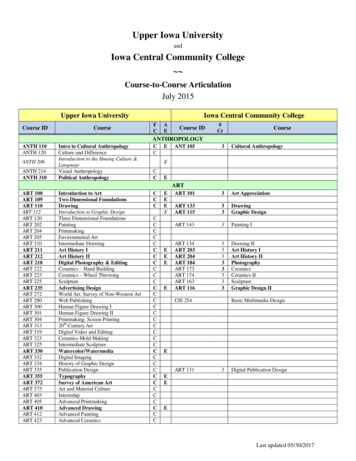
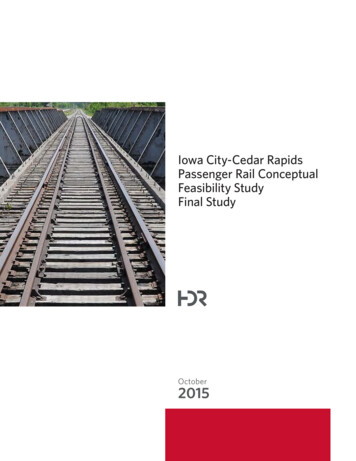
Example 2In the circuit at right, nd iR2.R139 ΩSince R1 and R2 are in series,they have the same current, ISand we can use the series2.2 Aequivalent. We can also ndthe equivalent resistance of thebranch with R4, R5, and R6.R212 ΩR3100 ΩR482 ΩiR2R556 ΩR6120 ΩR12 R1 R2 51 ΩR4 R5R456 R6 153 ΩR4 R5Then use a current divider on thesimpli ed circuit.iR2 1R121R12 1R31R4562.2 AR12R251 Ω i 100 ΩR2R456153 Ω IS 1.19 Afivoltage/current dividers – 7fifiG. Tuttle – 2022 IS
Example 32.2 kΩFind vR2 and vR4in the circuit.R1 VS–12 VR23.3 kΩ3.3 kΩ R3vR2R4– 3.3 kΩ vR4–We solve this using the voltage divider calculation twice in succession.First we nd vR2 using a voltage divider formed by R1 and the equivalentresistance of R2 in parallel with the series combination of R3 and R4.R234R2 R3vR2R4–R234 R2 (R3 R4) (3.3 kΩ) (6.6 kΩ) 2.2 kΩfiG. Tuttle – 2022VS –R1R234 vR2–R234vR2 VS 6 VR234 R1 vR2–R3R4 vR4–Then the voltagevR2 is dividedbetween R3 and R4.R4vR4 vR2 3 VR3 R4voltage/current dividers – 8
Example 4Find iR3 in the circuit.IS0.8 ASimilar to example 3, we cancascade dividers to nd thecurrent in two steps.iR2R222 ΩR133 ΩiR3 R422 ΩR322 ΩIS splits between R1 and the branch with R2, R3 , and R4. To nd thecurrent through R2, we use the equivalent resistance of that branch, whichforms a current divider with R1. Then iR2 is divided between R3 and R4.R222 ΩR2ISR234R422 ΩR234 R2 R3 R4iR2 1R11R234 1R234iR2 IS 0.4 AiR3 R4R3iR3 1R31R3 1R4 iR2 0.2 Avoltage/current dividers – 9fiG. Tuttle – 2022 3.3 kΩ0.8 AR23433 ΩfiR322 ΩR133 ΩiR2
Example 5Find the voltage vx indicatedin the circuit at right.By KVL, vx vR2 – vR4.VS110 V –We see that R1 and R2 form avoltage divider splitting VS. Thesame for R3 and R4.Using voltage dividers.R2vR2 VS 66 VR1 R2R4vR4 VS 10 VR3 R4Thenvx 66 V – 10 V 56 V.G. Tuttle – 2022VSR12.2 kΩR31 kΩ vx –R23.3 kΩR4R1R3100 Ω vx – –R2 vR2– vR4–R4voltage/current dividers – 10
Example 6Find the voltage vx indicatedin the circuit at right.As with the previous example, KVLtells us that vx vR2 – vR4.R12.2 kΩIS60 mAWe see that the series combinationR1 R2 forms a current divider withthe series combination R3 R4,splitting IS between the two branches.R31 kΩ vx –R23.3 kΩR4100 ΩR3iR3Using current dividers.iR1 iR3 1R1 R21R1 R2 1R3 R41R3 R41R1 R2 1R3 R4 IS 10 mA IS 50 mAvx iR1R2 – iR3R4 28 V.iR1 vx –ISThenG. Tuttle – 2022R1R2 vR2– vR4–R4voltage/current dividers –
Example 7In the circuit at right, the switch canbe opened or closed to control thevoltage across R3. When the switchVSis closed (R1 shorted out), vR3 istwice as big as the case when theswitch is open (R1 not shorted.) Howis R1 related to R2 R3? –R1R2R3 vR3–There are several approaches to answering this question, but usingvoltage dividers is a convenient method. With the switched closed, R1 isshorted out andvR3 2v′R3R3vR3 VSR32R3R2 R3 VS VSR2 R3R1 R2 R3With the switch open, R1R1 R2 R3 2 (R2 R3)R1 R2 R3 is part of the divider:R3v′R3 VSR1 R2 R3G. Tuttle – 2022voltage/current dividers – 12
Example 8In the circuit at right, the twoswitches can be opened orclosed to control the currentISthrough R3. Calculate the100 mAcurrent through R3 for allcombinations of the switchesbeing open closed.S1R11.5 kΩR23 kΩS2R33 kΩiR3S1 open and S2 open: iR3 IS 100 mAS1 open and S2 closed: iR3 S1 closed and S2 open: iR3 1R31R1S1 closed and S2 closed: iR3 G. Tuttle – 20221R2 1R3 1R11R31R3 IS 50 mA IS 33.3 mA1R3 1R2 1R3 IS 25 mAvoltage/current dividers – 13
switch is open (R 1 not shorted.) How is R 1 related to R 2 R 3? There are several approaches to answering this question, but using voltage dividers is a convenient method. With the switched closed, R 1 is shorted out and v R3 R 3 R 2 R 3 V S v R ′ 3 R 3 R 1 R 2 R 3 V S With the switch open, R 1 is part of the divider: v R3 .