Transcription
TDA7851L4 x 48 W MOSFET quad bridge power amplifierDatasheet production dataFeatures Multipower BCD technology High output power capability:– 4 x 48 W/4 Max.– 4 x 28 W/4 @ 14.4 V, 1 kHz, 10 %– 4 x 72 W/2 Max. MOSFET output power stage Excellent 2 driving capability Hi-Fi class distortion Low output noise Standby function Mute function Automute at min. supply voltage detection Low external component count:– Internally fixed gain (26 dB)– No external compensation– No bootstrap capacitors '!0'03 Flexiwatt 25– Reversed battery– ESDDescriptionProtections:– Output short circuit to GND, to VS, acrossthe load– Very inductive loads– Overrating chip temperature with softthermal limiter– Load dump voltage– Fortuitous open GNDTable 1.The TDA7851L is a breakthrough MOSFETtechnology class AB audio power amplifier inFlexiwatt25 package designed for high power carradio.The fully complementary P-Channel/N-Channeloutput structure allows a rail-to-rail output voltageswing which, combined with high output currentand minimized saturation losses sets new powerreferences in the car-radio field, with unparalleleddistortion performances.Device summaryOrder codePackagePackingTDA7851LFlexiwatt 25TubeSeptember 2013This is information on a product in full production.Doc ID 022520 Rev 31/15www.st.com1
ContentsTDA7851LContents1234Block diagram and application circuit . . . . . . . . . . . . . . . . . . . . . . . . . . . 51.1Block diagram . . . . . . . . . . . . . . . . . . . . . . . . . . . . . . . . . . . . . . . . . . . . . . . 51.2Application circuit . . . . . . . . . . . . . . . . . . . . . . . . . . . . . . . . . . . . . . . . . . . . 5Pin description . . . . . . . . . . . . . . . . . . . . . . . . . . . . . . . . . . . . . . . . . . . . . 62.1Pin connection . . . . . . . . . . . . . . . . . . . . . . . . . . . . . . . . . . . . . . . . . . . . . . 62.2Thermal data . . . . . . . . . . . . . . . . . . . . . . . . . . . . . . . . . . . . . . . . . . . . . . . 6Electrical specifications . . . . . . . . . . . . . . . . . . . . . . . . . . . . . . . . . . . . . . 73.1Absolute maximum ratings . . . . . . . . . . . . . . . . . . . . . . . . . . . . . . . . . . . . . 73.2Electrical characteristics . . . . . . . . . . . . . . . . . . . . . . . . . . . . . . . . . . . . . . . 73.3Electrical characteristic curves . . . . . . . . . . . . . . . . . . . . . . . . . . . . . . . . . . 9Application hints . . . . . . . . . . . . . . . . . . . . . . . . . . . . . . . . . . . . . . . . . . . 124.1SVR . . . . . . . . . . . . . . . . . . . . . . . . . . . . . . . . . . . . . . . . . . . . . . . . . . . . . 124.2Input stage . . . . . . . . . . . . . . . . . . . . . . . . . . . . . . . . . . . . . . . . . . . . . . . . 124.3Standby and muting . . . . . . . . . . . . . . . . . . . . . . . . . . . . . . . . . . . . . . . . . 124.4Heatsink definition . . . . . . . . . . . . . . . . . . . . . . . . . . . . . . . . . . . . . . . . . . 125Package information . . . . . . . . . . . . . . . . . . . . . . . . . . . . . . . . . . . . . . . . 136Revision history . . . . . . . . . . . . . . . . . . . . . . . . . . . . . . . . . . . . . . . . . . . 142/15Doc ID 022520 Rev 3
TDA7851LList of tablesList of tablesTable 1.Table 2.Table 3.Table 4.Table 5.Device summary . . . . . . . . . . . . . . . . . . . . . . . . . . . . . . . . . . . . . . . . . . . . . . . . . . . . . . . . . . 1Thermal data. . . . . . . . . . . . . . . . . . . . . . . . . . . . . . . . . . . . . . . . . . . . . . . . . . . . . . . . . . . . . 6Absolute maximum ratings . . . . . . . . . . . . . . . . . . . . . . . . . . . . . . . . . . . . . . . . . . . . . . . . . . 7Electrical characteristics . . . . . . . . . . . . . . . . . . . . . . . . . . . . . . . . . . . . . . . . . . . . . . . . . . . . 7Document revision history . . . . . . . . . . . . . . . . . . . . . . . . . . . . . . . . . . . . . . . . . . . . . . . . . 14Doc ID 022520 Rev 33/15
List of figuresTDA7851LList of figuresFigure 1.Figure 2.Figure 3.Figure 4.Figure 5.Figure 6.Figure 7.Figure 8.Figure 9.Figure 10.Figure 11.Figure 12.Figure 13.Figure 14.Figure 15.Figure 16.Figure 17.Figure 18.Figure 19.4/15Block diagram . . . . . . . . . . . . . . . . . . . . . . . . . . . . . . . . . . . . . . . . . . . . . . . . . . . . . . . . . . . . 5Application circuit . . . . . . . . . . . . . . . . . . . . . . . . . . . . . . . . . . . . . . . . . . . . . . . . . . . . . . . . . 5Pin connection (top view) . . . . . . . . . . . . . . . . . . . . . . . . . . . . . . . . . . . . . . . . . . . . . . . . . . . 6Quiescent current vs. supply voltage . . . . . . . . . . . . . . . . . . . . . . . . . . . . . . . . . . . . . . . . . . 9Output power vs. supply voltage (RL 4 ) . . . . . . . . . . . . . . . . . . . . . . . . . . . . . . . . . . . . . 9Output power vs. supply voltage (RL 2 ) . . . . . . . . . . . . . . . . . . . . . . . . . . . . . . . . . . . . . 9Distortion vs. output power (RL 4 ) . . . . . . . . . . . . . . . . . . . . . . . . . . . . . . . . . . . . . . . . . 9Distortion vs. output power (RL 2 ) . . . . . . . . . . . . . . . . . . . . . . . . . . . . . . . . . . . . . . . . . 9Distortion vs. frequency (RL 4 ). . . . . . . . . . . . . . . . . . . . . . . . . . . . . . . . . . . . . . . . . . . . 9Distortion vs. frequency (RL 2 ). . . . . . . . . . . . . . . . . . . . . . . . . . . . . . . . . . . . . . . . . . . 10Crosstalk vs. frequency . . . . . . . . . . . . . . . . . . . . . . . . . . . . . . . . . . . . . . . . . . . . . . . . . . . 10Supply voltage rejection vs. frequency . . . . . . . . . . . . . . . . . . . . . . . . . . . . . . . . . . . . . . . . 10Output attenuation vs. supply voltage. . . . . . . . . . . . . . . . . . . . . . . . . . . . . . . . . . . . . . . . . 10Power dissipation and efficiency vs. output power (RL 4 , SINE) . . . . . . . . . . . . . . . . . 10Power dissipation and efficiency vs. output power (RL 2 , SINE) . . . . . . . . . . . . . . . . . 10Power dissipation vs. output power (RL 4 , audio program simulation) . . . . . . . . . . . . 11Power dissipation vs. output power (RL 2 , audio program simulation) . . . . . . . . . . . . 11ITU R-ARM frequency response, weighting filter for transient pop. . . . . . . . . . . . . . . . . . . 11Flexiwatt25 mechanical data and package dimensions . . . . . . . . . . . . . . . . . . . . . . . . . . . 13Doc ID 022520 Rev 3
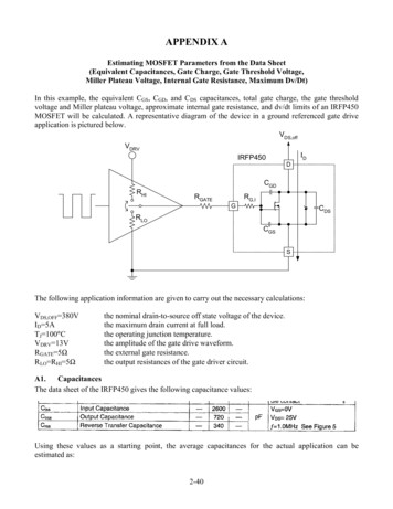
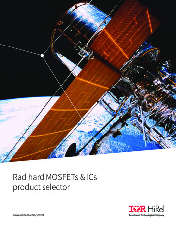
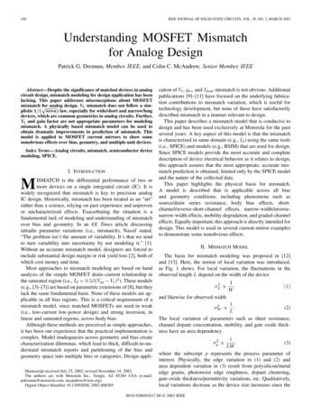
TDA7851LBlock diagram and application circuit1Block diagram and application circuit1.1Block diagramFigure 1.Block diagram6CC 6CC 34 "9# -54%/54 ). /54 07 '. /54 ). /54 07 '. /54 ). /54 07 '. /54 ). /54 07 '. !# '. 3624!"3 '. '!0'03 1.2Application circuitFigure 2.Application circuit# M&# M&6CC 6CC 2 34 "9 2 # M& -54% # M& # ). # M&). /54 # M& ). # M&/54 M&). /54 3 '. # M&/54 # M& 362 # 4!"2 6 # /54Doc ID 022520 Rev 3'!0'03 5/15
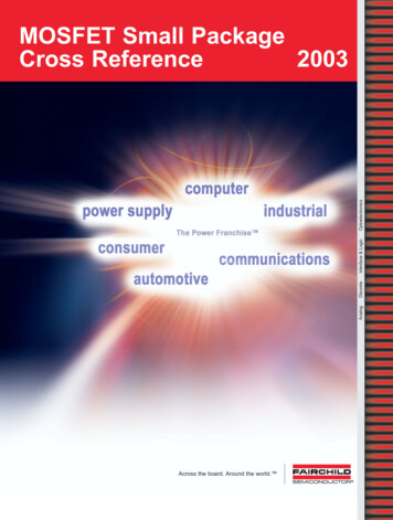
Pin descriptionTDA7851L2Pin description2.1Pin connectionPin connection (top view)0 '. -54%/54 6##/54 /54 /54 0 '. ). !# '. ). 3 '. ). ). 362/54 0 '. 6##/54 34 "9/54 /54 4!" 0 '. # Figure 3.'!0'03 2.2Thermal dataTable 2.SymbolRth j-case6/15Thermal dataParameterThermal resistance junction-to-caseDoc ID 022520 Rev 3MaxValueUnit1 C/W
TDA7851LElectrical specifications3Electrical specifications3.1Absolute maximum ratingsTable 3.Absolute maximum ratingsSymbolParameterValueUnitOperating supply voltage18VVS (DC)DC supply voltage28VVS (pk)Peak supply voltage (for t 50 ms)50VOutput peak currentNon repetitive (t 100 µs)Repetitive (duty cycle 10 % at f 10 Hz)109AAPower dissipation Tcase 70 C85WJunction temperature150 CVSIOPtotTj3.2TambOperating temperature range-40 to 105 CTstgStorage temperature-55 to 150 CElectrical characteristicsRefer to the test and application diagram, VS 14.4 V; RL 4 ; Rg 600 ; f 1 kHz;Tamb 25 C; unless otherwise specified.Table 4.Electrical characteristicsSymbolParameterTest conditionMin.Typ.Max.Unit8-18VVSSupply voltage range-Iq1Quiescent currentRL 100150300mAOutput offset voltagePlay mode / Mute mode-60- 60mV-10- 10mV-10- 10mV252627dB 1dBVOSDuring mute on/off output offsetvoltagedVOSITU R-ARM weightedDuring standby on/off output offset see Figure 18voltageGvVoltage gain-dGvChannel gain unbalance-PoPo max.Output powerMax. outputpower(1)VS 14.4 V; THD 10 %VS 14.4 V; THD 1 %VS 14.4 V; THD 10 %, 2 VS 14.4 V; THD 1 %, 2 VS 14.4 V; RL 4 VS 14.4 V; RL 2 VS 15.2 V; RL 4 Doc ID 022520 Rev 325-2822-WW-4838-WW-457548-WWW7/15
Electrical specificationsTable 4.TDA7851LElectrical characteristics (continued)SymbolParameterTest conditionMin.Typ.Max.UnitTHDDistortionPo 4 W-0.010.05%eNoOutput noise"A" WeightedBw 20 Hz to 20 kHz-3550100µVµVSVRSupply voltage rejectionf 100 Hz; Vr 1 Vrms5070-dBfchHigh cut-off frequencyPO 0.5 W100300-kHzRiInput impedance-70100130k CTCross talkf 1 kHz PO 4 Wf 10 kHz PO 4 W60-7060-dBdB-20µAStandby current consumptionVSt-by 1.2 V-ISBVSt-by 0--10µAIpin5Standby pin currentVSt-by 1.2 V to 2.6 V-- 1µAVSB outStandby out threshold voltage(Amp: ON)2.6--VVSB inStandby in threshold voltage(Amp: OFF)--1.2VMute attenuationPOref 4 W8090-dBVM outMute out threshold voltage(Amp: Play)2.6--VVM inMute in threshold voltage(Amp: Mute)--1.2V(Amp: Mute)Att 80 dB; POref 4 W6.77-V(Amp: Play)Att 0.1 dB; PO 0.5 W-7.58VVMUTE 1.2 V(Sourced current)71218µAVMUTE 2.6 V-5-18µAAMVAM inIpin23VS automute thresholdMuting pin currentClipping detectorCDLKClip detector high leakage currentCd off-01µACDSATClip detector saturation voltageDC On; ICD 1 mA-0.20.4VCDTHDClip detector THD level--2-%1. Saturated square wave output.8/15Doc ID 022520 Rev 3
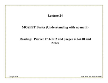
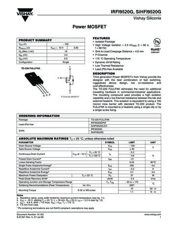
TDA7851LElectrical specifications3.3Electrical characteristic curvesFigure 4.Quiescent current vs. supplyvoltageFigure 5.)D M! Output power vs. supply voltage(RL 4 )0O 7 6I 2, c 0O MAX2, 7F (Z4( 4( 6S 66S 6Output power vs. supply voltage(RL 2 )Figure 7.0O 7 '!0'03 '!0'03 Figure 6. Distortion vs. output power(RL 4 )4( 0O MAX2, 7F (Z 6S 62, 7 F (Z4( F (Z4( 0O 76S 6Figure 8. '!0'03 Distortion vs. output power(RL 2 )'!0'03 Figure 9.4( 6S 62, 74( Distortion vs. frequency (RL 4 )6S 62, 70O 7F (Z F (Z F (Z0O 7'!0'03 Doc ID 022520 Rev 3'!0'03 9/15
Electrical specificationsTDA7851LFigure 10. Distortion vs. frequency (RL 2 )Figure 11. Crosstalk vs. frequency4( 6S 62, 70O 7 #2/334!, D" 2, 70O 72G 7 F (Z F (Z'!0'03 '!0'03 Figure 12. Supply voltage rejection vs.frequency Figure 13. Output attenuation vs. supplyvoltage/54054 !44. D"362 D" 2G 76RIPPLE 6RMS 2, 70O 7 REF 6S 6F (Z'!0'03 '!0'03 Figure 14. Power dissipation and efficiencyvs. output power (RL 4 , SINE)0TOT 7H H Figure 15. Power dissipation and efficiencyvs. output power (RL 2 , SINE) 6S 62, X 7F (Z 3).% 0TOT 7 6S 62, X 7F (Z 3).%H 0TOT 0O 710/15 0TOT '!0'03 Doc ID 022520 Rev 3 0O 7 '!0'03
TDA7851LFigure 16.Electrical specificationsPower dissipation vs. output power Figure 17.(RL 4 , audio program simulation)0TOT 7 0TOT 7 6S 62, X 7'!533)!. ./)3% 6S 62, X 7'!533)!. ./)3% #,)0 34!24Power dissipation vs. output power(RL 2 , audio program simulation) #,)0 34!24 0O 70O 7'!0'03 '!0'03 Figure 18. ITU R-ARM frequency response,weighting filter for transient pop/UTPUT ATTENUATION D" (Z'!0'03 Doc ID 022520 Rev 311/15
Application hints4Application hints4.1SVRTDA7851LBesides its contribution to the ripple rejection, the SVR capacitor governs the turn ON/OFFtime sequence and, consequently, plays an essential role in the pop optimization duringON/OFF transients. To conveniently serve both needs, its minimum recommended valueis 10 µF.4.2Input stageThe TDA7851L's inputs are ground-compatible and support very high input signals( 8 Vpk) without any performances degradation.If the standard value for the input capacitors (0.1µF) is adopted, the low frequency cut-offwill amount to 16 Hz.The input capacitors should be 1/4 of the capacitor connected to AC-GND pin for optimumpop performances.4.3Standby and mutingStandby and muting facilities are both CMOS-compatible. In absence of true CMOS ports ormicroprocessors, a direct connection to Vs of these two pins is admissible but a 470 k equivalent resistance should be present between the power supply and the muting andstand-by pins.R-C cells have always to be used in order to smooth down the transitions from preventingany audible transient noises.About the standby, the time constant to be assigned in order to obtain a virtually pop-freetransition has to be slower than 2.5 V/ms.4.4Heatsink definitionUnder normal usage (4 speakers) the heatsink's thermal requirements have to bededuced from Figure 16, which reports the simulated power dissipation when realmusic/speech programmes are played out. Noise with gaussian-distributed amplitude wasemployed for this simulation. Based on that, frequent clipping occurrence (worst-case) willcause Pdiss 26 W. Assuming Tamb 70 C and TCHIP 150 C as boundary conditions, theheatsink's thermal resistance should be approximately 2 C/W. This would avoid anythermal shutdown occurrence even after long-term and full-volume operation.12/15Doc ID 022520 Rev 3
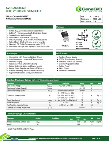
TDA7851LPackage informationIn order to meet environmental requirements, ST offers these devices in different grades ofECOPACK packages, depending on their level of environmental compliance. ECOPACK specifications, grade definitions and product status are available at: www.st.com.ECOPACK is an ST trademark.Figure 19. Flexiwatt25 mechanical data and package dimensions )- !"# %& '' ( ( ( ( , , , , , , - ./22 2 2 2 66 6 6 -). MM490 -!8 -). INCH490 -!8 /54,).% !. -%#(!.)#!, !4! &LEXIWATT VERTICAL 7\S 7\S 7\S 7\S DAM BAR PROTUSION NOT INCLUDED MOLDING PROTUSION INCLUDED6#"6(( 6 !( /( 2 , 2 6 2 , .2, 5Package information,, 6 6 2 2 , 0IN 2 2 %'' &&,%8 -%-- '!0'03 Doc ID 022520 Rev 313/15
Revision history6TDA7851LRevision historyTable 5.14/15Document revision historyDateRevisionChanges23-Nov-20111Initial release.13-Jun-20122Updated Features on page 1;Updated Section 3.2: Electrical characteristics on page 7.18-Sep-20133Updated Disclaimer.Doc ID 022520 Rev 3
TDA7851LPlease Read Carefully:Information in this document is provided solely in connection with ST products. STMicroelectronics NV and its subsidiaries (“ST”) reserve theright to make changes, corrections, modifications or improvements, to this document, and the products and services described herein at anytime, without notice.All ST products are sold pursuant to ST’s terms and conditions of sale.Purchasers are solely responsible for the choice, selection and use of the ST products and services described herein, and ST assumes noliability whatsoever relating to the choice, selection or use of the ST products and services described herein.No license, express or implied, by estoppel or otherwise, to any intellectual property rights is granted under this document. If any part of thisdocument refers to any third party products or services it shall not be deemed a license grant by ST for the use of such third party productsor services, or any intellectual property contained therein or considered as a warranty covering the use in any manner whatsoever of suchthird party products or services or any intellectual property contained therein.UNLESS OTHERWISE SET FORTH IN ST’S TERMS AND CONDITIONS OF SALE ST DISCLAIMS ANY EXPRESS OR IMPLIEDWARRANTY WITH RESPECT TO THE USE AND/OR SALE OF ST PRODUCTS INCLUDING WITHOUT LIMITATION IMPLIEDWARRANTIES OF MERCHANTABILITY, FITNESS FOR A PARTICULAR PURPOSE (AND THEIR EQUIVALENTS UNDER THE LAWSOF ANY JURISDICTION), OR INFRINGEMENT OF ANY PATENT, COPYRIGHT OR OTHER INTELLECTUAL PROPERTY RIGHT.ST PRODUCTS ARE NOT DESIGNED OR AUTHORIZED FOR USE IN: (A) SAFETY CRITICAL APPLICATIONS SUCH AS LIFESUPPORTING, ACTIVE IMPLANTED DEVICES OR SYSTEMS WITH PRODUCT FUNCTIONAL SAFETY REQUIREMENTS; (B)AERONAUTIC APPLICATIONS; (C) AUTOMOTIVE APPLICATIONS OR ENVIRONMENTS, AND/OR (D) AEROSPACE APPLICATIONSOR ENVIRONMENTS. WHERE ST PRODUCTS ARE NOT DESIGNED FOR SUCH USE, THE PURCHASER SHALL USE PRODUCTS ATPURCHASER’S SOLE RISK, EVEN IF ST HAS BEEN INFORMED IN WRITING OF SUCH USAGE, UNLESS A PRODUCT ISEXPRESSLY DESIGNATED BY ST AS BEING INTENDED FOR “AUTOMOTIVE, AUTOMOTIVE SAFETY OR MEDICAL” INDUSTRYDOMAINS ACCORDING TO ST PRODUCT DESIGN SPECIFICATIONS. PRODUCTS FORMALLY ESCC, QML OR JAN QUALIFIED AREDEEMED SUITABLE FOR USE IN AEROSPACE BY THE CORRESPONDING GOVERNMENTAL AGENCY.Resale of ST products with provisions different from the statements and/or technical features set forth in this document shall immediately voidany warranty granted by ST for the ST product or service described herein and shall not create or extend in any manner whatsoever, anyliability of ST.ST and the ST logo are trademarks or registered trademarks of ST in various countries.Information in this document supersedes and replaces all information previously supplied.The ST logo is a registered trademark of STMicroelectronics. All other names are the property of their respective owners. 2013 STMicroelectronics - All rights reservedSTMicroelectronics group of companiesAustralia - Belgium - Brazil - Canada - China - Czech Republic - Finland - France - Germany - Hong Kong - India - Israel - Italy - Japan Malaysia - Malta - Morocco - Philippines - Singapore - Spain - Sweden - Switzerland - United Kingdom - United States of Americawww.st.comDoc ID 022520 Rev 315/15
September 2013 Doc ID 022520 Rev 3 1/15 1 . The fully complementary P-Channel/N-Channel output structure allows a rail-to-rail ou tput voltage swing which, combined with high output current . The input capacitors should be 1/4 of the capacitor connected to AC-GND pin for optimum pop performances. 4.3 Standby and muting