Transcription
Lecture 25MOSFET Basics (Understanding with Math)Reading: Pierret 17.1-17.2 and Jaeger 4.1-4.10 andNotesGeorgia TechECE 3040 - Dr. Alan Doolittle
MOS Transistor I-V DerivationWith our expression relating the Gate voltage to the surface potential andthe fact that S 2 F we can determine the value of the threshold voltageVT 2 F VT 2 F S2qN AC ox S 2 F S2qN D 2 F C ox S(for n - channel devices)(for p - channel devices)where,C ox oxxoxis the oxide capacitance per unit areaWhere we have made use of the use of the expression, S KS oGeorgia TechECE 3040 - Dr. Alan Doolittle
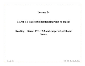
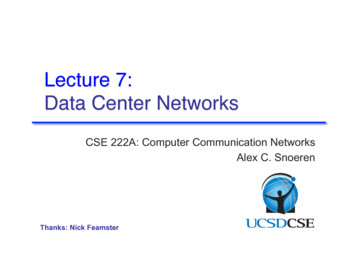
MOS Transistor I-V DerivationCoordinate Definitions for our “NMOS” Transistorx depth into the semiconductorfrom the oxide interface.y length along the channel fromthe source contactz width of the channelxc(y) channel depth (variesalong the length of the channel).n(x,y) electron concentrationat point (x,y) n(x,y) the mobility of thecarriers at point (x,y)Georgia TechDevice width is ZChannel Length is LAssume a “Long Channel” device (fornow do not worry about the channellength modulation effect) ECE 3040 - Dr. Alan Doolittle
MOS Transistor I-V DerivationConcept of Effective mobilityThe mobility of carriers near the interface issignificantly lower than carriers in thesemiconductor bulk due to interfacescattering.Since the electron concentration also varieswith position, the average mobility ofelectrons in the channel, known as theeffective mobility, can be calculated by aweighted average, n x xc ( y )x 0 n ( x, y )n( x, y )dxx xc ( y )x 0Empirically n n( x, y )dxor defining ,QN ( y ) q x xc ( y )x 0n( x, y )dx ch arg e / cm q x xc ( y ) n n ( x, y )n( x, y )dx x 0QN ( y )Georgia Tech o1 VGS VT where, o and are constants2ECE 3040 - Dr. Alan Doolittle
MOS Transistor I-V DerivationDrain Current-Voltage RelationshipIn the Linear Region, VGS VT and 0 VDS VdsatJ N q n nE qDN nNeglecting the diffusion current, and recognizing the current isonly in the y-direction,J N J NyGeorgia Techd q n nE y q n ndyECE 3040 - Dr. Alan Doolittle
MOS Transistor I-V DerivationDrain Current-Voltage RelationshipIn the Linear Region, VGS VT and 0 VDS VdsatI D J Ny dxdz Z x xc ( y )x 0J Ny dxx xc ( y ) d q n ( x, y )n( x, y )dx Zx 0 dy d Z n QNdy y Ly 0 VDSI D dy Z n 0 VDSI D L Z n 0 Z nID LGeorgia Tech VDS 0Q N d QN d Q N d To find ID, we need an expression relating theelectrostatic potential, and QN ECE 3040 - Dr. Alan Doolittle
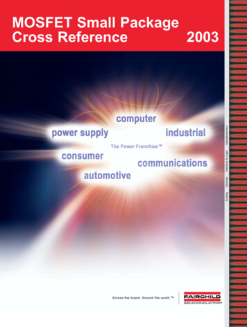
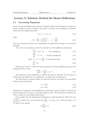
MOS Transistor I-V Derivation“Capacitor-Like” Model for QNAssumptions: Neglect all but the mobile inversion charge (valid for deep inversion) For the MOSFET, the charge in the semiconductor is a linear function ofposition along the semiconductor side of the plate. Thus, varies from 0 to VDSSince Cox dQ,dVSourceMOS CapacitorOnly voltages above threshold create inversion chargeQN Cox VGS VT for VGS VTNeglect the depletion region chargeGeorgia TechDrainMOS TransistorQN Cox VGS VT for VGS VTNote: Assuming a linear variation of potential along the channelleads to an underestimation of current but is a good estimate forhand calculations.ECE 3040 - Dr. Alan Doolittle
MOS Transistor I-V DerivationUsing “Capacitor-Like” Model for QN we can estimate ID as: Z n VID 0 QN d DSL Z nID L VDS Z n C oxID L 0 C ox VG VT d 2 VDS VGS VT V DS 2 0 V DS V Dsatand VGS VTThis is known as the “square law” describing theCurrent-Voltage characteristics in the “Linear” or“Triode” region.Note the linear behavior for small VDS (can neglect VDS2 term). Notethe negative parabolic dependence for larger VDS but still VDS VDsat(can NOT neglect VDS2 term).Georgia TechECE 3040 - Dr. Alan Doolittle
MOS Transistor I-V Derivation“Capacitor-Like” Model for QNBut what about the saturation region?For VDS Vdsat the voltage drop across our channel is VDsat with the remaining voltage(VDS-VDsat) dropped across the pinch-off regionI D I DsatZ n C ox L2 V Dsat VVV GS TDsat2 V Dsat V DSBut the charge at the end of the channel is zero due to the pinched off channel,Q N ( y L) C ox VGS VT V Dsat 0VGSor VT V DsatThus,I D I Dsat Georgia Tech Z n C ox VGS VT 22L V Dsat V DSECE 3040 - Dr. Alan Doolittle
MOS Transistor I-V DerivationSummary of MOSFET IV RelationshipZ n C oxID L0 VDS2 VDS VVV GS TDS2 V Dsat and VGS VTI D I Dsat Z n C ox VGS VT 22L V Dsat V DSVDsat VGS VTGeorgia TechECE 3040 - Dr. Alan Doolittle
MOS Transistor ApplicationsVoltage variable ResistorAn n-channel MOSFET has a gate width to length ratio of Z/L 100, un 200cm2/Vsec, Cox 0.166 uF/cm2 and VT 1V. We want to develop a resistor that hasa resistance that is controlled by an external voltage. Such a device would be usedin “variable gain amplifiers”, “automatic gain control devices”, “compressors” andmany other electronic devices. Define what range of VDS must be maintained toachieve proper “voltage variable resistance” operation. Find the “On-resistance”(VDS/ID) of the transistor from 1.5V VGS 4Vfor small VDS .First, to achieve voltage variable resistance operation, we must operate in thelinear region. Otherwise, the current is either a constant regardless of drainvoltage (saturation region) or is approximately zero (cutoff due to the capacitorbeing in either accumulation and depletion).Thus, VGS -VT VDS. Given the values above, 0 VDS 0.5VContinued.Georgia TechECE 3040 - Dr. Alan Doolittle
MOS Transistor ApplicationsVoltage variable ResistorUsing the linear region ID equation:Z n C oxID LRDSRDS2 Z n C oxVDS VGS VT VDS for small VDSV VV GS TDS2 L LV DSV DSZ IDZ n C ox n C ox VGS VT VGS VT VDS L0.01 200 0.166e 6 F / cm 2 VGS 1 Thus,100 RDS 600 Georgia TechECE 3040 - Dr. Alan Doolittle
MOS Transistor ApplicationsCurrent SourceThe same transistor is to be used for a “Current Source”. Define the range ofdrain-source voltage that can be used to achieve a fixed current of 50 uA.For a constant current regardless of Drain-Source voltage, we must use thesaturation region: Z n C ox VGS VT 2VDsat VDS2L100 200cm 2 / VSec 0.166uF / cm 2 VGS 1 250uA 2VGS 1.173VI D I Dsat This source will operate over a VDS VGS-VT or VDS 0.173 VGeorgia TechECE 3040 - Dr. Alan Doolittle
MOS Transistor: Deviations From IdealChannel Length Modulation EffectAbove “pinch-off” (when VDS VDsat VGS-VT) the channel length reducesby a value L.Thus, the expression for drain current,I D I Dsat Z n C ox VGS VT 22LBecomes,I D I Dsat Z nCox VGS VT 2 2 L L or since * L L,I D I Dsat V Dsat VDS VDsat VDS11 L 1 L L L L L Z nCox2 VGS VT 1 2LL VDsat VDS*In many modern devices, this assumption does not hold. Thus, the channel length modulation parameter we are deriving does not describe the IVexpressions well.Georgia TechECE 3040 - Dr. Alan Doolittle
MOS Transistor: Deviations From IdealChannel Length Modulation EffectBut the fraction of the channel that is pinched offdepends linearly on VDS because the voltageacross the pinch-off region is (VDS-VDsat) so, L V DSLChannel Length Modulationcauses the dependence of draincurrent on the drain voltage insaturation.where is known as the Channel-LengthModulation parameter and is typically:0.001 V-1 V I D I DsatGeorgia Tech Z n C ox VGS VT 2 1 VDS 2LV Dsat VDSECE 3040 - Dr. Alan Doolittle
MOS Transistor: Deviations From IdealBody Effect (Substrate Biasing)Until now, we have only consideredthe case where the substrate (Body)has been grounded . but the substrate (Body) is oftenintentionally biased such that theSource-Body and Drain-Bodyjunctions are reversed biased.The body bias, VBS, is known as the backgate bias and can be used to modify thethreshold voltage.Note that now our channel potential has an offset equal to VBS, .Georgia TechECE 3040 - Dr. Alan Doolittle
MOS Transistor: Deviations From IdealBody Effect (Substrate Biasing)Thus, our threshold potential with the body grounded,VT 2 F VT 2 F S2qN AC ox S 2 F S2qN D 2 F C ox S(for n - channel devices)(for p - channel devices)Surface Potential SThe Gate- Body Threshold becomes,2qN D 2 F VBS (for p - channel devices)VGB 2 F VBS SCox SThresholdVGB Threshold 2 F VBS SCox2qN A S 2 F VBS (for n - channel devices)But we would like to have this in terms of VGS instead of VGB.Since, VGS VGB VBSVGS Threshold 2 F VT Georgia TechVGS Threshold 2 F S2qN AC ox S 2 F VBS S2qN D 2 F VBS C ox S(for n - channel devices)(for p - channel devices)ECE 3040 - Dr. Alan Doolittle
MOS Transistor: Deviations From IdealBody Effect (Substrate Biasing)This can be rewritten in the following form (more convenient to reference the thresholdvoltage to the VBS 0 case). 2 2 VT Pierret VTN Jaeger VTO F VBS 2 FVT Pierret VTP Jaeger VTOF VBS 2 F (for n - channel devices)(for p - channel devices)where, Georgia Tech2qN A SC oxis known as the body effect parameterECE 3040 - Dr. Alan Doolittle
MOS Transistor:Enhancement Mode verses Depletion Mode MOSFETWe have been studying the “enhancement mode” MOSFET(Metal-Oxide-Semiconductor Field Effect Transistor). It is called“enhancement” because conduction occurs only after the channelconductance is “improved” or “enhanced”. In this case,VTN 0 and VTP 0Transistors can be fabricated such that: VTN 0 and VTP 0These transistors have conduction for VGS 0 due to a channelalready existing without the need to “invert the near surfaceregion”. To modulate currents, a field must applied to the gate thatdepletes the channel. Thus, transistors of this nature are called“Depletion mode MOSFETs”.Georgia TechECE 3040 - Dr. Alan Doolittle
MOS Transistor:Enhancement Mode verses Depletion Mode MOSFETGeorgia TechECE 3040 - Dr. Alan Doolittle
MOS channel)Jaeger uses the notation:NMOSK n K n'WW n Coxwhere W is the Gate Width (Z in Pierret)LLPMOSK p K p'Georgia TechWW p Coxwhere W is the Gate Width (Z in Pierret)LLECE 3040 - Dr. Alan Doolittle
MOS Transistor:SummaryNMOSPMOSRegardless of ModeK n K n'CutoffWWWW p Cox(Note : W Z in Pierret) n C ox(Note : W Z in Pierret) K p K 'pLLLLI DS 0LinearI DSZ n C ox LVGS VTNSaturationfor VGS VTN2 VDS VVV GSTNDS2 andVGS VTN VDS 0 VGSThreshold VoltageVTN VTO VT for EnhancementModeVT for DepletionModeGeorgia Tech Z n C ox VGS VTN 2 1 VDS 2L VTNandV DS VGS VTN 0I DS 2 F VSB 2 F I DS 0for VGS VTP2 Z n C ox VDSID VGS VTP V DS L2 VGS VTPandVGS VTP VDS 0VGS Z n C ox VGS VTP 2 1 VDS 2L VTPandVDS VGS VTP 0I DS VTP VTO 2 F VBS 2 F VTN 0VTP 0VTN 0VTP 0ECE 3040 - Dr. Alan Doolittle
MOS Transistor:Bias Circuitry-Enhancement Mode NMOSDue to zero DC current flow in the gate, the bias analysis of a MOSFETis significantly easier than a BJT.ABCGeorgia Tech Form Thevenincircuits looking outthe gate, drain, andsourceECE 3040 - Dr. Alan Doolittle
MOS Transistor:Bias Circuitry-Enhancement Mode NMOS3V I G Rth VGS10V I DS R3 VDSIG But IG 0 so VGS 3V Assume Saturation operation (selected foreasy math because IDS does not depend onVDS since no was given – 0): IDS Kn vGS VTN 2 for v DS vGS VTN 0225 x10 6 3 1 2 50 Ai DS 2Check V DSi DS 10V 50uA(100k ) VDSVDS 5V VGS VTN 2V Assumption of Saturation operation was correct! If it were not correct simplymake another assumption (I.e. linear region) and resolve.Georgia TechECE 3040 - Dr. Alan Doolittle
MOS Transistor:Bias Circuitry-Depletion Mode NMOS Bias circuit of a depletion mode device is much simpler due to the factthat the device conducts drain current for VGS 0VVTO 3V 0 VK n 200 uA What value of R1 results in 100 uA drain current? Again Assuming saturation:V2 Kn vGS VTN 2 for v DS vGS VTN 022 I DS2 100uA VTN 3V 2VKn200uA / V 2i DS VGS IDSR1 VGS 2 20 K I DS100uACheck V DS10V I DS R1 V DS 100uA 20k V DSV DS 8V VGS VTN 2V ( 3V ) 1V Assumption of Saturation operation was correct! If it were not correct simplymake another assumption (I.e. linear region) and resolve.Georgia TechECE 3040 - Dr. Alan Doolittle
PMOS Transistor:Bias Circuitry-Enhancement Mode PMOSVTO 1V 0 VK p 25 uAID IS VGS VTPV2 KZ n C ox VGS VTP 2 1 VDS p VGS VTP 22L2andV DS VGS VTP 0 1. 5 M 6V R EQ 1M 1.5M 600 K 1.5M 1M I S RS VGS I G RG V EQV EQ 10VV DDV DD V EQ RSKp2 VGS2 25 E 6 2.66 1 2 34.4 A2 I D RS V DS I D R D V DS 6.08VID V DD 25 E 6 VGS 1 2 VGS2 7.21 0 VGS 2.71 or 2.66V10 6 4 39,000VGS2 0.051VGS VTP VGSCheck V DSV DS VGS VTP 0 6.08 2.66 ( 1) 0Georgia TechECE 3040 - Dr. Alan Doolittle
MOS Transistor:Bias Circuitry-Possible Combinations1) Vth Base VGS I DS Rth Source Vth Source2) I DSand K2 n VGS VTN 1 VDS 2optionally , AssumeorI DS2 VDS K n VGS VTN VDS 2 either saturated or linear/triode.3) Vth Drain VDS I DS Rth Source Rth Drain Vth Source Always: Solve 1) for VGS and plug into 2). In certain cases, VDS will need to be eliminated by using3) solved for VDS and plugged into 2). Case A: Saturated, and 0 and no source resistor –only 1 and 2 required. Results in 1st order polynomial. Case B: Saturated, and 0 and no source resistor – all3 equations needed. Results in 1st order polynomial. Case C: Saturated, and 0 and a source resistor – all 3equations needed. Results in 2nd order polynomial. Case D: Saturated, and 0 and a source resistor – all 3equations needed. Results in 3rd order polynomial. Case E: Linear/Triode, with or without a source resistor– all 3 equations needed. Results in 2nd orderpolynomial.Georgia TechECE 3040 - Dr. Alan Doolittle
Useful Formulas for DC Bias SolutionsIf a 3rd order polynomial results, try factoring it into a linear and quadratic term 1st. Ifthis is not easy for your case, a longer but sure fire way is listed below.Georgia TechECE 3040 - Dr. Alan Doolittle
Georgia Tech ECE 3040 - Dr. Alan Doolittle Lecture 25 MOSFET Basics (Understanding with Math)


![Academy Cloud Foundations Course Outline [English]](/img/13/academy-20cloud-20foundations-20course-20outline-20-english.jpg)
