Transcription
450IEEE JOURNAL OF SOLID-STATE CIRCUITS, VOL. 38, NO. 3, MARCH 2003Understanding MOSFET Mismatchfor Analog DesignPatrick G. Drennan, Member, IEEE, and Colin C. McAndrew, Senior Member, IEEEAbstract—Despite the significance of matched devices in analogcircuit design, mismatch modeling for design application has beenlacking. This paper addresses misconceptions about MOSFETmismatch for analog design. t mismatch does not follow a simplistic 1 ( area) law, especially for wide/short and narrow/longdevices, which are common geometries in analog circuits. Further,t and gain factor are not appropriate parameters for modelingmismatch. A physically based mismatch model can be used toobtain dramatic improvements in prediction of mismatch. Thismodel is applied to MOSFET current mirrors to show somenonobvious effects over bias, geometry, and multiple-unit devices.Index Terms—Analog circuits, mismatch, semiconductor devicemodeling, SPICE.I. INTRODUCTIONMISMATCH is the differential performance of two ormore devices on a single integrated circuit (IC). It iswidely recognized that mismatch is key to precision analogIC design. Historically, mismatch has been treated as an “art”rather than a science, relying on past experience and unprovenor uncharacterized effects. Exacerbating the situation is afundamental lack of modeling and understanding of mismatchover bias and geometry. In an EE Times article discussingintradie parameter variations (i.e., mismatch), Nassif stated,“The problem isn’t the amount of variability. It’s that we tendto turn variability into uncertainty by not modeling it.” [1].Without an accurate mismatch model, designers are forced toinclude substantial design margin or risk yield loss [2], both ofwhich cost money and time.Most approaches to mismatch modeling are based on handanalysis of the simple MOSFET drain–current relationship in). These modelsthe saturated region (i.e.,(e.g., [3]–[7]) are based on parametric extensions of [8], but theylack the same fundamental basis. None of these models are applicable in all bias regions. This is a critical requirement of amismatch model, since matched MOSFETs are used in weak(i.e., low-current low-power design) and strong inversion, inlinear and saturated regions, across body bias.Although these methods are perceived as simple approaches,it has been our experience that the practical implementation iscomplex. Model inadequacies across geometry and bias createcharacterization dilemmas, which lead to thick, difficult-to-understand mismatch reports and partitioning of the bias andgeometry space into multiple bins or categories. Design appliManuscript received July 25, 2002; revised November 14, 2002.The authors are with Motorola Inc., Tempe, AZ 85284 USA (e-mail:pdrennan@motorola.com, mcandrew@ieee.org).Digital Object Identifier 10.1109/JSSC.2002.808305cation of , , andmismatch is not obvious. Additionalpublications [9]–[11] have focused on the underlying fabrication contributions to mismatch variation, which is useful fortechnology development, but none of these have satisfactorilydescribed mismatch in a manner relevant to design.This paper describes a mismatch model that is conducive todesign and has been used exclusively at Motorola for the pastseveral years. A key aspect of this model is that the mismatchis characterized in same domain (e.g., ) using the same tools(i.e., SPICE) and models (e.g., BSIM) that are used for design.Since SPICE models provide the most accurate and completedescription of device electrical behavior as it relates to design,this approach assures that the most appropriate, accurate mismatch prediction is obtained, limited only by the SPICE modeland the nature of the collected data.This paper highlights the physical basis for mismatch.A model is described that is applicable across all biasand geometry conditions, including phenomena such assource/drain series resistance, body bias effects, shortchannel/reverse-short-channel effects, narrow-width/inversenarrow-width effects, mobility degradation, and graded-channeleffects. Equally important, this approach is directly intended fordesign. This model is used in several current-mirror examplesto demonstrate some nonobvious effects.II. MISMATCH MODELThe basis for mismatch modeling was proposed in [12]and [13]. Here, the notion of local variation was introduced,as Fig. 1 shows. For local variation, the fluctuations in theobserved length depend on the width of the deviceand likewise for observed width(2)The local variation of parameters such as sheet resistance,channel dopant concentration, mobility, and gate oxide thickness have an area dependency(3)represents the process parameter ofwhere the subscriptinterest. Physically, the edge variation in (1) and (2) andarea dependent variation in (3) result from polysilicon/metaledge grains, photoresist edge roughness, dopant clustering,gate-oxide thickness/permittivity variations, etc. Qualitatively,local variations decrease as the device size increases since the0018-9200/03 17.00 2003 IEEE
DRENNAN AND McANDREW: UNDERSTANDING MOSFET MISMATCH FOR ANALOG DESIGN451TABLE IRELEVANT PROCESS AND ELECTRICAL PARAMETERSFig. 1. Global variation and local variation. For local variation, the variancein length depends on the width.parameters “average” over a greater distance or area. This iscontrasted with global process parameter variation which isindependent of length and width . As per [14], mismatch(i.e., intradie parameter variation) is comprised of local variation but traditional interdie (die-to-die) variation, used for bestcase and worst case models and statistical simulation, containsboth global and local components. In fact, in many instances oftechnology, device-type, geometry, and bias, the local variationcomponent dominates the interdie variation [15]. This impliesan additional geometric dependence that is rarely accounted forin interdie statistical models [16].The model in (1) was derived by evaluating the local lengthandin Fig. 1) across the entire width and finding(e.g.,the second moment (i.e., the standard deviation) of the effectivelength. An alternative derivation [8] has been used to describemismatch behavior over geometry. This model assumes that theobserved variation for a given parameter is the convolution ofthe small-signal parameter spatial variation over the device area.This model is identical to (3). Perimeter contributions to mismatch were not addressed in [8], but a similar derivation resultsin (1).Although the model in [8] was derived correctly, it is incorand gain factor . Theserectly applied to threshold voltagetwo parameters are combined to produce the mismatch(4)One immediately apparent problem is the physical basis forthese parameters. As pointed out in [17] and later in [18], if theunderlying cause for mismatch variation is the gate-oxide thickwillness , it will be accounted for in both and , thus,be overestimated by a factor as large as two.For mismatch modeling, one can consider two types ofparameters: process and electrical (see Table I). Processparameters are those physically independent parameters thatcontrol the electrical behavior of a device. Electrical parametersare those parameters that are of interest to the designer.mismatch does not belong in either category.is not a process parameter. depends on,and(the effective value of which depends on body bias), throughthe “short-channel effect” and “reverse-short-channel effect,”through the “narrow-width” and “inverse-narrow-widthandeffect.” In addition, 0.18- m and smaller technologies use haloor pocket ion implantations which introduce new length andwidth dependencies. This means that the relationship(5)is physically incorrect, and measured data from many technologies confirm this. In [4], the attempt was made to accommodatethe otherwise anomalous scaling behavior by using the effective), but this is not approlength and width (i.e.,priate for the same reason that short and narrow channel effectsand. In practice, theare not modeled with just withgeometric scaling inadequacies of (5) are often circumventedby creating local models for geometric subsets of the overalldesignable geometry space. This approach introduces practicalcomplexities and discontinuities in the model.mismatch is often assumed to be the input offset voltagewhich is an electrical parameter, butmismatch(6)Even using the simplistic mismatch relationship in (4), it is apis not the input offset voltage, because neitherparent thatnoris constant over bias, especially for graded-channelis. The consedevices such as the halo-implanted device, yetquences of this distinction will be made apparent in Section III.Inadequate geometry selection in the mismatch test structuredesign of experiments hides the shortcomings of (5). Several. Barring anydifferent gate areas are used to extract theother considerations, often these geometries are selected about. This establishes a self-fulfilling situation in which anerroneous model appears to fit the data well. Departures in thetrue mismatch behavior from the assumed model cannot be detected and evaluated. Large model prediction errors result forwide/short and narrow/long MOSFETs. These geometries arecritical to analog design.
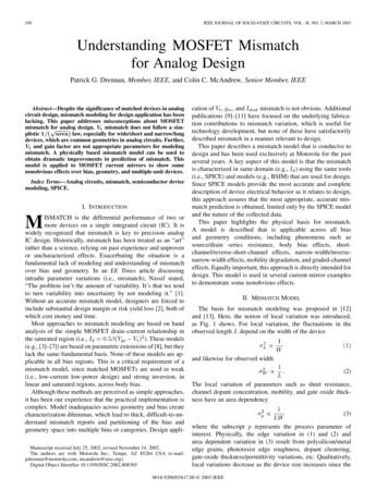
452IEEE JOURNAL OF SOLID-STATE CIRCUITS, VOL. 38, NO. 3, MARCH 2003(4) and (5). A detailed discussion of the characteristics of theseplots is given in [18].Applying (8) to MOSFET mismatch producesgeometry(10)where the geometric dependency of the process parameter variation is given in (1)–(3). Expanding (10) givesFig. 2. Graphical depiction of the propagation of variance.A physically complete and accurate mismatch model is givenin [18] for MOSFETs and [19] for bipolar junction transistors(BJTs). All mismatch models are based on the propagation ofvariance (POV) relationship depicted in Fig. 2. For a given independent variable and a dependent variable(7)as described byConsidering the range of possible values ofthe probability density function (pdf) of and building a pdfyields the POV relationship(8)where is any electrical parameter and is the th independentprocess parameter, listed in Table I. In the case of MOSFETs,normal distributions are assumed. For BJT mismatch models,log-normal distributions are required for some parameters, butthat is outside the scope of this paper. For MOS mismatchmodels other than [18], the partial derivatives in (8) are basedon the simplistic model(9)and as process parameters, andor extensions of (9), withas the electrical parameter. Combining (9) and (8) yields (4).The mismatch model in [18] is more complete since it usesBSIM3 (or another SPICE MOSFET model) to evaluate the partial derivative in (8), which is substantially more accurate thanusing a simple analytic model like (9). Unlike the mismatchmodel in (4), [18] is valid in the linear and saturation regions,for subthreshold, weak inversion, and strong inversion conditions, and for all geometries, as shown in the plots of measuredand simulated data for nMOS transistors in Fig. 3. A partialcomparison of the modeling approaches is given across bias inFig. 4 and across geometry in Fig. 5, for a nMOS device in a0.25- m CMOS technology. It is worth noting that the comparison of models in Figs. 4 and 5 are given for large gate voltages(1.8 and 2.5 V). As the gate voltage decreases, the departurein modeling approaches increases. Clearly, there is a significant improvement of the model [18] over the standard approach,(11)above a variable indicates a normalized paraThe tildemeter. For characterization, the vector on the left side of (11)mismatch standard deviations collected acrossis a set ofmany dies for many biases and geometries, typically hundredsof combinations. The combinations are chosen so that theprocess parameter mismatch variances are observable in themismatch data, with a unique and unconfounded solution. Foronly significantly affectsfor short devices ininstance,, so we measure mismatch underthe linear region for highcannot be considered inthese conditions. Conversely,mismatch characterization schemes that contain , , and/ormismatch measurements, because it is not reflected inthose parameters. This is a likely explanation of the resultsobtained in [22].The large middle matrix in (11) contains the squares of thesensitivities of with respect to each of the process parameters.Each row of sensitivities is numerically evaluated using SPICEat the bias and geometry conditions at which the correspondingis measured. Hence, the bias conditions and geometries forthe measured devices must be chosen to ensure that each processparameter can be uniquely observed above the measurementerror.Given the first two matrices in (11), the rightmost vectorof process parameters can be calculated using analytic simplelinear regression. This method is called back propagation ofvariance (BPV). Essentially, process parameter variations areover bias andextracted that best explain the measuredgeometry. Each process parameter is assumed to be independent. If a correlation exists between process parameters, that isan indication that a wrong or incomplete set of process parameters has been selected. Correlations can always be addressedwith the inclusion of the appropriate set of independent processand(or) mismatch areparameters. For instance,partially correlated, depending on the relative contribution of
DRENNAN AND McANDREW: UNDERSTANDING MOSFET MISMATCH FOR ANALOG DESIGN453Fig. 3. Array of plots of measured and simulated mismatch data for an nMOS device on a 0.18- m technology [20]. The geometry selection is based upon thedesign of experiments in [21]. Circle, square, and diamond symbols are measured data at V0:1 V; 0:9 V; and 1:8 V, respectively. Lines are model at thesame conditions. with principle component analysis (PCA), which is strictlyempirical with no physical basis or interpretation.Note that the process parameters in the right-side vector of(11) contain the local variation geometric scaling as prescribedby (1)–(3). This means that geometric scaling is applied to boththe variance and the sensitivity components on the right side of(8). The geometric scaling affects the sensitivities through theunderlying SPICE MOSFET model.III. MISMATCH APPLICATIONFig. 4. NMOS I mismatch over bias, 0.25- m CMOS technology, W L 7 0:56 m 2:5 V. Symbols are data.0. An appropriate reparameterization ofand mismatch,, , and. BPV should not be confusedwould useAn accurate mismatch model is not useful unless it can bepractically used for design. The specific intention of the characterization approach described here is its application in SPICEthrough Monte Carlo or sensitivity analysis. We use MOSFETcurrent mirrors to illustrate some nonobvious mismatch phenomena. Similar analysis can be used for other applications suchas differential pairs and much larger circuit blocks.
454IEEE JOURNAL OF SOLID-STATE CIRCUITS, VOL. 38, NO. 3, MARCH 2003V NMOS I mismatch versus L, 0.25- m CMOS technology, W 7 m, 2:5; V 2:5 V. Symbols are data.Fig. 5.0Fig. 6. Three-dimensional (3-D) plot of I mismatch versus L and W for annMOS current mirror, I 10 A, 0.13- m CMOS technology.Fig. 7.I3-D plot ofImismatch versus geometry, graded-channel nMOS, at 10 A, 0.25- m BiCMOS technology.I mismatch and the underlying process parameter contributions forL 25 m in Fig. 7. “gc” subscript indicates parameters specific to the gradedFig. 8.channel.A. Geometry and Bias InterrelationshipWhat is the best way to size devices in a current mirror to meetmatching requirements? A MOSFET current mirror is biasedwith a current, so the gate voltage depends on geometry. Intuincreases,itively, as the gate overdrive voltagehave less impact on the misthose parameters that effectmatch. This is even apparent in (4).increases, the intrinsic mismatch decreases as perAsincreases to supply the same ref(1)–(3). At the same time,erence current. Both the sensitivity local parameter components.in (8) also decrease, constructively combining to decreaseincreases, the intrinsic mismatch compoHowever, asdecreases. These two effects offsetnent decreases, buteach other, and as Fig. 6 shows, can give rise to little or noimprovement in mismatch with increasing . Depending onthe underlying dominant mismatch process parameters, bettermatching can be obtained without consuming additional area,aspect ratio. This improvementsimply by changing thecomes at the expense of reduced dynamic range sinceincreases and, hence, the linear/saturation transition point for(i.e.,) increases.For graded-channel MOSFETs [23] (and halo-implanteddevices), the geometry and bias tradeoff can have a muchmore profound impact, as Fig. 7 shows. Here, a dramaticratios.improvement in mismatch is obtained with smallTo further explore this, a cut alongm in Fig. 7 is givenin Fig. 8. For wider devices, the mismatch is dominated bythe dopant concentration and the length of the graded-channelregion. Since the channel dopant concentration is highest in thegraded-channel region (versus the bulk dopant concentration),this region effectively sets the threshold voltage of the device.increases, thereby reducing the senAs the device narrows,to the graded-channel components. Of particularsitivity ofinterest is that the geometric dependency of is determinedby the local process parameter definition, but the geometricdependency of the graded-channel regions is determined bythe sensitivity component of (10) and (11). Mismatch does noton mismatchblindly depend on area alone. The impact ofalso means that mismatch is not constant if the referencecurrent is not constant, such as in an active load (see Fig. 9).Thus, current mirror mismatch depends strongly on andnot . Proper sizing of MOSFETs in current mirrors requires amismatch model that is accurate over both bias and geometry.B. NMOS or PMOS?A common question is, “Which matches better, nMOS orpMOS?” The answer depends on how a device is biased. Withvoltage bias, there is no consistent trend across technologies.With current bias, the lower mobility for pMOS means that
DRENNAN AND McANDREW: UNDERSTANDING MOSFET MISMATCH FOR ANALOG DESIGN455TABLE IIIIMPACT OF MULTIPLE UNIT DEVICES ON CURRENT MIRROR MISMATCH FOR AIS SCALED2 2 m nMOS DEVICE ON A 0.13- m CMOS PROCESS. IFOR THE REFERENCE DEVICE TO MAINTAIN CONSTANT VOLTAGE BIAS2Fig. 9. Current mirror I mismatch versus ICMOS technology.FOR 2ON A 0.4-MISMATCH, W L 2 2 m, 0.13- mTABLE IINMOS AND PMOS DEVICES m-POWER BiCMOS PROCESS2 2 mdividing the 20- m device mismatch by. This consistencyis an important consideration when selecting the geometricdependency in the rightmost vector in (11).Where integer current scaling is desired, the matching of a1 : ratio differs from an : 1 ratio. If devices are placed inparallel, each device contributes additional mismatch variance.The situation for current mirrors is slightly different, becausemultiple-unit devices in the reference transistor are mappedthrough the gate voltage. As Table III shows, the majority ofthe improvement from using multiple parallel devices is gainedby using them for the output, not the reference device.IV. CONCLUSIONa largeris required to supply the same reference or tailcurrent, thereby improving the mismatch as compared with annMOS device. Table II shows this effect for complementarystandard-logic nMOS and pMOS devices in a 0.4- m-powerBiCMOS process. In almost all cases, complementary pMOSdevices will appear to have better matching than nMOS whenbiased with current. More generally, mismatch tradeoffs appeardifferently to characterization and device engineers (who typically bias devices with voltages) than to design engineers (whomismatchoften bias devices with current). Metrics such asmay not be particularly meaningful. Device-type, geometry, andbias comparisons for mismatch must be performed in the designapplication.C. Multiple-Unit DevicesWide/short MOSFETs are often used in design, particularlyis needed.in differential pair applications where a highThese devices are broken up into smaller unit MOSFETs andcombined to compact the layout and to reduce parasitic sourceand drain junction capacitances. When multiple-unit devicesare placed in parallel, the process parameter variance component in (10) increases by a factor of , because each MOSFETcontains its own local parameter variation. On the other hand,the squared sensitivities decrease by a factor of n , becauseeach device has less impact of the current. Thus, overalldecreases by a factor of, per (10). This is consistent withthe definition of local parameter variation. For example, an- m-wide80- m-wide device can be broken up intodevices. Neglecting width effects, the mismatch variability fora single 20- m-wide device will be twice the variability ofthe 80- m-wide device per (1) and (3), which is the same asAccurate mismatch modeling is needed to avoid parametricyield loss and overdesign. The common approach to MOSFETmismatch modeling, based on and , leads to inaccurate predictions over geometry and bias. Mismatch modeling based onphysical process parameters is significantly more accurate.In addition, because the approach is based on physicaluncorrelated process parameters, the characterization procedureidentifies the parameters that have the greatest contributionto mismatch. This helps process technologists identify keyareas to work on when trying to optimize a process for bestmismatch.REFERENCES[1] R. Wilson, “The dirty little secret: Engineers at design forum vexed byrise in process variations at the die level,” EE Times, p. 1, Mar. 25, 2002.[2] K. Bult and A. Buchwald, “An embedded 240-mW 10-b 50-MS/sCMOS ADC in 1-mm ,” IEEE J. Solid-State Circuits, vol. 32, pp.1887–1895, Dec. 1997.[3] S. C. Wong et al., “A CMOS mismatch model and scaling effects,” IEEEElectron Device Lett., vol. 18, pp. 261–263, June 1997.[4] S. Lovett et al., “Characterizing the mismatch of submicron MOS transistors,” in IEEE Int. Conf. Microelectronic Test Structures, vol. 9, Mar.1996, pp. 39–42.[5] T. Serrano-Gotarredona and B. Linares-Barranco, “A new five-parameter MOS transistor mismatch model,” IEEE Electron Device Lett., vol.21, pp. 37–39, Jan. 2000.[6] Q. Zhang et al., “SPICE modeling and quick estimation of MOSFETmismatch based on BSIM3 model and parametric tests,” IEEE J. SolidState Circuits, vol. 36, pp. 1592–1595, Oct. 2001.[7] J. A. Croon et al., “An easy-to-use mismatch model for the MOS transistor,” IEEE J. Solid-State Circuits, vol. 37, pp. 1056–1064, Aug. 2002.[8] M. J. Pelgrom et al., “Matching properties of MOS transistors,” IEEE J.Solid-State Circuits, vol. 24, pp. 1433–1440, Oct. 1989.[9] H. P. Tuinhout and M. Vertregt, “Test structures for investigation of metalcoverage effects on MOSFET matching,” in IEEE Int. Conf. Microelectronic Test Structures, Mar. 1997, pp. 179–183.
456[10] H. P. Tuinhout et al., “Effects of gate depletion and boron penetration onmatching of deep submicron CMOS transistors,” in IEEE Int. ElectronDevices Meeting, Dec. 1997, pp. 631–634., “Impact of ion implantation statistics on V fluctuations in MOS[11]FETs: comparison between Decarborane and Boron channel implants,”in Proc. VLSI Symp., 2000, pp. 134–135.[12] J. B. Shyu et al., “Random errors in MOS capacitors,” IEEE J. SolidState Circuits, vol. SC-17, pp. 948–955, Dec. 1982., “Random error effects in matched MOS capacitors and current[13]sources,” IEEE J. Solid-State Circuits, vol. SC-19, pp. 1070–1076, Dec.1984.[14] C. C. McAndrew, “Modeling for circuit simulation,” in Proc. IEEECustom Integrated Circuits Conf., Education Session, May 2000, pp.E1–1.[15] R. Difrenza et al., “Comparison between matching parameters and fluctuations at the wafer level,” in Proc. IEEE Int. Conf. MicroelectronicTest Structures, Apr. 2002, pp. 241–246.[16] C. C. McAndrew and P. G. Drennan, “Unified statistical modeling forcircuit simulation,” in Proc. 5th Int. Conf. Modeling and Simulation ofMicrosystems, Apr. 2002, pp. 715–718.[17] K. R. Lakshmikumar, R. A. Hadaway, and M. A. Copeland, “Characterization and modeling of mismatch in MOS transistors for precisionanalog design,” IEEE J. Solid-State Circuits, vol. SC-21, pp. 1057–1066,Dec. 1986.[18] P. G. Drennan and C. C. McAndrew, “A comprehensive MOSFET mismatch model,” in Proc. IEEE Int. Electron Devices Meeting, Dec. 1999,pp. 167–170., “A comprehensive vertical BJT mismatch model,” in Proc. IEEE[19]Bipolar/BiCMOS Circuits and Technology Meeting, Sept. 1998, pp.83–86.[20] J. Kirchgessner et al., “A 0.18- m SiGe : C RFBiCMOS technologyfor wireless and gigabit optical communication applications,” in Proc.IEEE Bipolar/BiCMOS Circuits and Technology Meeting, Sept. 2001,pp. 151–154.[21] P. G. Drennan, “Diffused resistor mismatch modeling and characterization,” in Proc. IEEE Bipolar/BiCMOS Circuits and Technology Meeting,Sept. 1999, pp. 27–30.[22] M. Bolt, “Matching properties of MOS transistors and delay line chainswith self-aligned source/drain contacts,” in Proc. IEEE Int. Conf. Microelectronic Test Structures, Mar. 1996, pp. 21–25.IEEE JOURNAL OF SOLID-STATE CIRCUITS, VOL. 38, NO. 3, MARCH 2003BiCMOS[23] F. K. Chai et al., “A cost-effective 0.25- m Ltechnology featuring graded-channel CMOS (GCMOS) and aquasi-self-aligned (QSA) NPN for RF wireless applications,” in Proc.IEEE Bipolar/BiCMOS Circuits and Technology Meeting, Sept. 2000,pp. 110–113.Patrick G. Drennan (M’96) received the B.S. degree in microelectronic engineering and the M.S. degree in electrical engineering from the Rochester Institute of Technology, Rochester, NY, in 1991 and1993, respectively, and the Ph.D. degree in electricalengineering from Arizona State University, Tempe,in 1999.He joined Motorola, Semiconductor ProductsSector, Tempe, in 1992, where he is currently aDistinguished Member of the Technical Staff. Hisprofessional interests include mismatch modeling,simulation, monitoring, and debugging for analog circuit design.Colin C. McAndrew (S’82–M’84–SM’90) receivedthe B.E. (Hons) degree in electrical engineering fromMonash University, Melbourne, Victoria, Australia,in 1978, and the M.A.Sc. and Ph.D. degrees insystems design engineering from the Universityof Waterloo, Waterloo, ON, Canada, in 1982 and1984, respectively.From 1978 to 1980 and from 1984 to 1987, he waswith the Herman Research Laboratories, State Electricity Commission, Victoria. From 1987 to 1995, hewas with AT&T Bell Laboratories, Allentown, PA.Since 1995, he has been with Motorola, Tempe, AZ, and is currently Directorof the Enabling Technology Center. His research interests are in compact andstatistical modeling and characterization for circuit simulation.Dr. McAndrew is on the Technical Program Committees for the IEEEBipolar/BiCMOS Circuits and Technology Meeting, the IEEE InternationalConference on Microelectronic Test Structures, and the IEEE Custom Integrated Circuits Conference, and is an Editor of the IEEE TRANSACTIONS ONELECTRON DEVICES.
circuit design, mismatch modeling for design application has been lacking. This paper addresses misconceptions about MOSFET mismatch for analog design. t mismatch does not follow a sim-plistic 1 ( area) law, especially for wide/short and narrow/long devices, which are common