Transcription
Hardware MaintenanceHardware Maint
Copyright 2006 EqualLogic, Inc.September 2006EqualLogic is a registered trademark of EqualLogic, Inc.All trademarks and registered trademarks mentioned herein are the property of theirrespective owners.Possession, use, or copying of the documentation or the software described in thispublication is authorized only under the license agreement.EqualLogic, Inc. will not be held liable for technical or editorial errors or omissionscontained herein. Information in this document is subject to change.PS Series Firmware Version 3.0Part Number: 110-0040-R2ii
Table of ContentsPreface .vIntroduction to PS Series Storage Arrays .1Steps for Setting Up and Using an Array .2Step 1. Set Up the Array Hardware .3A. Unpack Shipping Box and Gather Hardware .3B. Mount Array in a Stable Rack .6C. Connect Power Cables for Grounding .8D. Connect Array to a Network Switch .9E. Turn on Power to Array and Check LEDs for Errors .12F. Connect Array to a Console Terminal .15Step 2. Configure the Array and Create a Group .16Step 3. Set the RAID Policy .19Using the GUI to Set the RAID Policy .19Using the CLI to Set the RAID Policy .23Step 4. Create a Volume .25Using the GUI to Create a Volume .26Using the CLI to Create a Volume .29Step 5. Connect to the Volume from a Host System .30Advanced Operations and More Information .31Index .35iii
PrefaceThis QuickStart describes how to set up EqualLogic PS Series 3000 storage arrayhardware and create a PS Series group—a self-managing, iSCSI storage areanetwork (SAN) that is affordable and easy to use, regardless of scale.After setting up the group, see the PS Series Group Administration manual forinformation about managing the group.AudienceThis QuickStart is designed for administrators responsible for setting up arrayhardware and creating a group. Although administrators do not need extensivenetwork or storage system experience, it may be useful to understand: Basic networking conceptsCurrent network environmentUser disk storage requirementsRAID configurationsDisk storage managementNote: This QuickStart describes using PS Series arrays in some common networkconfigurations. However, detailed information about setting up a networkis beyond its scope.OrganizationThis QuickStart is organized as follows: Introduction to PS Series Storage Arrays Steps for Setting Up and Using an ArrayStep 1. Set Up the Array HardwareStep 2. Configure the Array and Create a GroupStep 3. Set the RAID PolicyStep 4. Create a VolumeStep 5. Connect to the Volume from a Host System Advanced Operations and More Informationv
PS Series 3000 QuickStartPrefaceEqualLogic WebsiteThe EqualLogic website, www.equallogic.com, has the latest productfirmware and documentation, in addition to warranty information.Product Documentation and Technical SupportFor detailed information about PS Series arrays, groups, and volumes, see thefollowing documentation: Release Notes. Provides the latest information about PS Series arrays. QuickStart. Describes how to set up the PS Series Model 3000 array hardwareand create a PS Series group. Group Administration. Describes how to use the Group Manager graphicaluser interface (GUI) to manage a PS Series group. This manual providescomprehensive information about product concepts and procedures. CLI Reference. Describes how to use the Group Manager command lineinterface (CLI) to manage a PS Series group and individual arrays. Hardware Maintenance. Provides information about maintaining thePS Series Model 3000 array hardware.The QuickStart and the Hardware Maintenance manual are printed and shippedwith the product. They are also located on the documentation CD-ROM that isshipped with the product, along with the Group Administration and CLI Referencemanuals and the Group Manager online help.In addition, the Host Integration Tools for Windows systems are available on theEqualLogic website and on a CD-ROM that is shipped with the product.Technical support on EqualLogic products is available for customers with arraysunder warranty and customers with a valid support contract. You can obtaintechnical support in the following ways: Visit the EqualLogic Customer Support website to download the latestdocumentation and firmware. Go to www.equallogic.com and log in toyour support account. If you do not have an account, register for an account. From the EqualLogic Customer Support website, you can submit a servicerequest.vi
PS Series 3000 QuickStartPreface In the United States, call 877-887-7337. International customers should call 00 1 919-767-5729. If the issue is urgent, ask to speak with a member of theEqualLogic Customer Support team. Send e-mail to support@equallogic.com and clearly describe the issue orproblem.Online HelpFor help on the Group Manager graphical user interface (GUI) and command lilneinterface (CLI), click Tools in the bottom left corner of the GUI window toexpand the menu. Then, click Online Help.The Group Manager CLI also provides help at the command line. In addition, thesetup utility provides help for each prompt.Warranty InformationThe license agreement and warranty information are included in the PS Seriesarray shipping box. To register your array, go to www.equallogic.com, clickSupport, and then click warranty registration.Restricted Access RequirementPS Series arrays must be installed in a restricted access location. A restrictedaccess location is an area that is intended only for qualified or trained personnel.vii
Introduction to PS Series Storage ArraysEqualLogic PS Series storage arrays deliver the benefits of consolidated storage ina storage area network (SAN) that is affordable and easy to use—regardless of itssize. With intelligent, automated management and fast, flexible scalability,PS Series arrays greatly reduce storage acquisition and management costs. ThisQuickStart describes how to start using your PS Series array.By grouping together one or more PS Series arrays connected to an IP network,you can create a PS Series group—a highly-scalable iSCSI SAN with a sharedpool of storage space. Integrated virtualization software makes a group easy tomanage and provides automatic RAID configuration, data provisioning, and loadbalancing. To increase SAN capacity and performance, connect another array tothe network and add it to the group—data remains online at all times.To ensure high reliability, PS Series storage arrays include RAID-protecteddisks, automatic disk sparing, redundant fans and power supplies, and dualhigh-performance control modules, each with three Gigabit Ethernet interfacesand a battery-backed cache.A simple setup utility lets you quickly configure an array as a member of a newor existing group. RAID configuration and load balancing (network and data)occur automatically. Both graphical and command line user interfaces areavailable for group management.In a multi-member group, you can separate space into storage pools, which allowyou to organize storage according to usage, providing more control over resourceallocation, while maintaining a single system management view.Using the Group Manager graphical or command line user interface, you createvolumes, assigning to each volume a pool, size, access controls, and otherattributes. A volume can be spread across multiple disks and group members andis seen on the network as an iSCSI target. Members and volumes can movebetween pools to meet business objectives.To connect to a volume, a host needs only a standards-compliant iSCSI initiator.Volume access can be restricted through IP address, initiator name, or CHAP(Challenge Handshake Authentication Protocol) credentials. Once connected, thevolume is seen by the host as a regular disk that can be formatted as usual.1
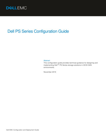
PS Series 3000 QuickStartSteps for Setting Up and Using an ArrayAt a minimum, a group consists of one array with one network connection,but you can configure three network interfaces for maximum array bandwidth.Data and network I/O are automatically load balanced across disks andinterfaces—with no impact on data availability.PS Series Group With Multiple MembersYou can easily increase group capacity and bandwidth by adding arrays. When anarray is added to a group, it obtains the group configuration from the existingmembers. Once you choose a RAID policy for the member, the pool isautomatically expanded, and volume data and network I/O are load balancedacross the pool members’ disks and network connections. Volumes continueto be accessible through the same iSCSI targets, and no host modifications arenecessary. Management overhead remains the same, regardless of the group size.Steps for Setting Up and Using an ArrayTo start using your PS Series array:Step 1.Set up the array hardware configuration.Step 2.Configure the array on the network and create a group.Step 3.Log in to the group and specify the RAID policy for the array.Step 4.Create a volume.Step 5.Connect to the volume from a host system.2
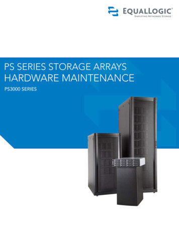
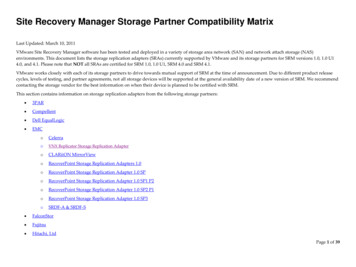
PS Series 3000 QuickStartStep 1. Set Up the Array HardwareStep 1. Set Up the Array HardwareA. Unpack Shipping Box and Gather HardwareThe order in which you unpack the shipping box is important for safety:1. Open the outer shipping box and remove the accessory box.2. Remove the accessories and ensure that you have the contents shown in thefigure Shipping Box Contents.3. Following the unpacking instructions in the shipping box, lift the array andplace it on a flat surface that is protected from electrostatic discharge. Do notremove the plastic bag from the array until you are ready to install it in a rack.4. Gather the hardware that is not included in the box, as described in the tableRequired Hardware – Not Supplied.The array is heavy. Do not attempt to lift or install the array withoutassistance.Shipping Box Contents3
PS Series 3000 QuickStartStep 1. Set Up the Array HardwareDescription of Shipping Box ContentsComponentDescription3U storage arraychassisContains one or two control modules, two powersupply/cooling modules, and eight or 16 disks.Power cablesConnects an array to one or more power sources. The shippingbox may contain multiple power cables to meet the electricalrequirements of the country in which the array will reside.Caution: Be sure to use only these enclosed power cables withthis product.Serial null modemcableCreates a serial connection between an array and a console orterminal emulator. The cable has two DB9, 9-pin, femaleconnectors and is used only for the initial member and groupconfiguration or if there is no network access to the array.Four-pole rackassembly kitEnables you to install an array in a four-pole rack. Instructionsfor assembly are included in the kit.Two-pole rackassembly kitEnables you to install an array in a two-pole rack. Instructionsfor assembly are included in the kit.Electrostatic wrist strap Protects sensitive hardware from electrical discharge.Documentation andCD-ROMsPrinted documentation includes the PS Series QuickStart,Hardware Maintenance, Release Notes, and SAN setup poster.The Group Administration and CLI Reference manuals andthe Group Manager online help are on the documentationCD-ROM, along with the QuickStart and HardwareMaintenance manuals.Host Integration Tools for Windows systems and relateddocumentation are on the HIT CD-ROM.License and warranty information is also included in theshipping box.Note: Product returns will be accepted only in the original packaging or inauthorized packaging obtained from your PS Series support provider.4
PS Series 3000 QuickStartStep 1. Set Up the Array HardwareArray installation also requires the hardware described in Required Hardware –Not Supplied. This hardware is not provided with your array.Required Hardware – Not SuppliedComponentDescriptionStandard 19” twoor four-pole rackProvides easy access to storage arrays and other hardware in yourcomputing environment.One or morenetwork cablesConnects an array to a network switch. Use Category 5E orCategory 6 cables with RJ45 connectors. You can also useCategory 5 cables if they adhere to the TIA/EIA TSB95 standard.Only one network connection is required for operation, but asmany as six connections (maximum of three active) are possible.Network switchConnects devices to a network. If possible, connect the array todifferent switches for high availability.Computer or aconsole terminalEnables you to perform the initial array and group configuration ormanage the group when there is no active network connection. Acomputer must be running a terminal emulator.The following table describes the optional hardware that you can use in a storagearray installation. This hardware is not provided with your array.Optional Hardware – Not SuppliedComponentDescriptionOne or two UPSsystemsProvide a highly available source of power to an array. Each UPSsystem should be on a different circuit and must provide the correcttype of voltage for an adequate amount of time.5
PS Series 3000 QuickStartStep 1. Set Up the Array HardwareB. Mount Array in a Stable RackA PS Series array must be mounted in a two-pole or four-pole 19” rack.Instructions for rack assembly and mounting an array are included with thetwo-pole assembly kit and the four-pole assembly kit in the array shipping box.When mounting an array in a rack, you must meet the following recommendationsand requirements: Be sure there is sufficient space for air flow in front of and behind the array. It is recommended that you attach the rack to the floor for added stability. Be sure to support the array until it is completely mounted in the rack. The location of the array must be properly vented and must meet theenvironmental, power, and physical requirements described in thefollowing table.PS Series Storage Array RequirementsComponentRequirementWeight of fully-loaded array80 pounds or 36.36 kilogramsOperating temperature41 to 104 degrees F / 5 to 40 degrees CStorage temperature-22 to 140 degrees F / -30 to 60 degrees CMaximum altitude10,000 feetOperational relative humidity8 to 90% non-condensingThermal output of fully-loaded array2200 BTU/hour, 660 wattsShock30 G for 2 msVibration.1 G @ 10 to 100 hertzInput voltage90 to 264 VAC (auto-sensing)Input current5.5 amperes (maximum, single power supply)@ 120 voltsInput frequency50 to 60 hertzInput power660 VAPower suppliesDual, 450 watts DC outputHeight/Width/Depth5.25” x 17 5/8” x 22.5”13.33 cm x 44.77 cm x 56.25 cm6
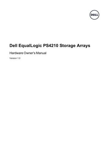
PS Series 3000 QuickStartStep 1. Set Up the Array HardwareFour-Pole Rack ExampleBe sure to support the array until it is completely mountedin the rack.Two-Pole, Mid-Mount Rack Example7
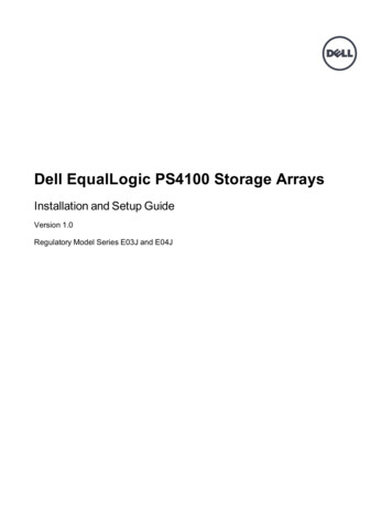
PS Series 3000 QuickStartStep 1. Set Up the Array HardwareC. Connect Power Cables for GroundingA PS Series array includes two power supply/cooling modules. It is recommendedthat you connect both power supplies to different sources of power, preferably onseparate circuits for increased availability.For a highly-available power configuration, connect one power supply to anuninterruptible power supply (UPS) system, and connect the other power supplyto a different source of power. See the table PS Series Storage Array Requirementson page 6 for information about voltage requirements.Notes: Do not turn on power to the array. At this time, the power cables are onlyfor grounding purposes.If your PS Series array was shipped with power cables, use these cables tomeet safety requirements.To connect power cables to an array, refer to the figure shown next. Be sure to usethe cable strain relief when securing the power cable in the array.Connecting Power Cables8
PS Series 3000 QuickStartStep 1. Set Up the Array HardwareD. Connect Array to a Network SwitchA PS Series array includes one or two control modules. Only one control moduleis active (serving network traffic) at one time. The secondary (redundant) controlmodule mirrors cache data from the active control module. If the active controlmodule fails, the secondary will take over network operations.Each control module has three Ethernet network interface ports, labeled PORT 0,PORT 1, and PORT 2, for up to three active connections to the network.In addition to the requirements and recommendations described in the followingtables, all the usual rules for proper network configuration apply to the groupmembers. General network configuration is beyond the scope of this document.Network RequirementsRequirementDescriptionAn array must have at least one functioning network interfaceOne or morenetwork connections connected to a network (through a network switch, if possible).When you configure the array, as described later in thisQuickStart, you assign an IP address and netmask to this interface.In a dual control module array, to ensure network availabilityregardless of which control module is active, connect a cable tothe network interface port on each control module.Correct networkcablesUse Category 5E or Category 6 cables with RJ45 connectors. Youcan also use Category 5 cables if they adhere to the TIA/EIATSB95 standard.Network RecommendationsRecommendation DescriptionSwitched GigabitEthernet networkConnect arrays and hosts to a switched network and ensure that allnetwork connections between hosts and arrays are GigabitEthernet. An array can operate at 10 and 100 Mbits, butperformance will be significantly degraded.Multiple networkconnectionsFor increased bandwidth and availability, connect multiplenetwork interfaces to the network (and different switches, ifpossible). Connect interfaces in the following order: PORT 0,PORT 1, and PORT 2.After the initial setup, use the Group Manager GUI or CLI toassign an IP address and netmask to each additional interface.9
PS Series 3000 QuickStartStep 1. Set Up the Array HardwareNetwork Recommendations (Continued)Recommendation DescriptionAccess to the groupIP addressIn a multi-subnet group, each configured network interface shouldhave access to the subnet on which the group IP address resides.Redundant networkpathsUsing a multipathing solution helps to ensure that no single pointof failure exists between hosts and arrays.For replication, areliable, adequatelysized network linkFor effective and predictable replication, be sure that the networklink between the primary and secondary groups is reliable andprovides sufficient bandwidth for copying data.No STPfunctionality onswitch ports thatconnect end nodesDo not use Spanning-Tree (STP) on switch ports that connect endnodes (iSCSI initiators or storage array network interfaces).However, if you want to use STP or RSTP (preferable to STP),you should enable the port settings available on some switchesthat let the port immediately transition into STP forwarding stateupon link up. This functionality can reduce network interruptionsthat occur when devices restart, and should only be enabled onswitch ports that connect end nodes.Note: The use of Spanning-Tree for a single-cable connectionbetween switches is encouraged, as is the use of trunkingfor multi-cable connections between switches.Flow ControlEnable Flow Control on each switch port and NIC that handlesenabled on switches iSCSI traffic. PS Series arrays will correctly respond to Flowand NICsControl.Unicast stormcontrol disabled onswitchesDisable unicast storm control on each switch that handles iSCSItraffic, if the switch provides this feature. However, the use ofbroadcast and multicast storm control is encouraged on switches.Jumbo FramesEnable Jumbo Frames on each switch and NIC that handles iSCSIenabled on switches traffic to obtain any performance benefit and ensure consistentand NICsbehavior.VLANs10Configure switches to use VLANs in order to separate iSCSI SANtraffic from other network traffic.
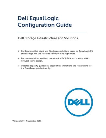
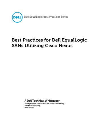
PS Series 3000 QuickStartStep 1. Set Up the Array HardwareThe minimum network configuration for a single control module array is onenetwork connection to PORT 0. The minimum network configuration for a dualcontrol module array is one network connection to PORT 0 on each controlmodule, as shown in the figure Minimum Dual Control Module NetworkConfiguration. This configuration protects against control module failure.Minimum Dual Control Module Network ConfigurationFor maximum network bandwidth and availability, connect cables to all networkports and distribute the connections across multiple network switches, as shown inthe figure High Performance, High-Availability Network Configuration.High Performance, High-Availability Network Configuration11
PS Series 3000 QuickStartStep 1. Set Up the Array HardwareE. Turn on Power to Array and Check LEDs for ErrorsBefore turning on power, be sure the array is at room temperature. If an LEDindicates a problem, contact the support provider for your PS Series array.Disk LEDsBackpanel LEDsDisk LED DescriptionsDisk LEDsTopBottomColorOffGreenFlashing greenOffRedDescriptionNo power or error condition.Power.Disk activity.No power or normal condition.Error condition.Operations Panel LED DescriptionsOperations LEDs ColorDescriptionPower (upper right) OffNo power.Green12Power.
PS Series 3000 QuickStartStep 1. Set Up the Array HardwareOperations Panel LED Descriptions (Continued)Operations LEDs ColorDescriptionArray locator (upper OffNo power or normal condition.left)Flashing orange Administrator enabled the array locator function.Warning condition(lower left)OffError condition(lower right)OffNo power or normal condition.Flashing orange One or more of the following has occurred: RAID set is degraded but still functioning. RAID set (volume level) has lost blocks. Component temperature is near a limit. Fan has failed or RPMs exceed opper orlower limit. Power supply is not installed or has no power. Only one control module installed or controlmodule has failed over. Active control module syncing withsecondary. No communication between control modules. No replication progress for more then 1 hour. Installed spare disk does not have enoughcapacity to replace a disk in a RAID set. A non-critical hardware component failed.No power or normal condition.Flashing orange One or more of the following has occurred: RAID is not functioning. Lost block table is full. Temperature exceeds upper or lower limit. Control module cache has lost data. One or both fan trays are not installed. Both fans on a fan tray have failed. Cache battery has less than 72 hours of chargeor temperature is too high to charge battery. NVRAM coin cell battery has failed. Cache contains data that does not belong toany of the installed disks. More than one valid RAID set exists in array. Control modules are different models. A critical hardware component has failed. Operations panel failed or not installed. Storage enclosure processor that monitorsarray components has experienced a failure.13
PS Series 3000 QuickStartStep 1. Set Up the Array HardwareControl Module LED DescriptionsControl Module LEDsColorDescriptionACTOffNo power, secondary control module is notsynchronized with active control module,or error condition.GreenActive control module (serving network I/O).OrangeSecondary control module; cache issynchronized with active control module.OffNo power or no error condition.RedArray is starting up or error condition.OffNo power.GreenPower.ERRPWRNetwork Interface LED DescriptionsNetwork Interface LEDs ColorDescriptionLeftOffNo power or not connected to network.GreenConnected to network.OffNo power or not transmitting.GreenTransmitting.RightPower Supply/Cooling Module LED DescriptionsPower Supply/CoolingModule LEDColorDescriptionOffNo power or normal conditionOrangeDC power failureOffNo power or normal conditionOrangeFan failureOffNo power or normal conditionOrangeAC power failureOffNo powerGreenNormal array operation 14
PS Series 3000 QuickStartStep 1. Set Up the Array HardwareF. Connect Array to a Console TerminalEstablish a serial connection between the array and a console terminal (or acomputer running a terminal emulator) to run the setup utility, which enablesyou to configure the array and add it to a group. After setting up the array, theserial connection is not needed, but you should keep the serial cable. You can usea serial connection if there is no network access to the group or array.Note: If you have a Microsoft Windows system, you can use the EqualLogicRemote Setup Wizard to configure an array and create a group instead ofusing the setup utility. The wizard does not require the serial cable.The serial connection must have the following characteristics: 9600 baudOne STOP bitNo parity8 data bitsNo hardware flow controlTo create a serial connection, obtain the null modem cable that shipped with thearray and refer to the next figure. The serial cable must always be connected toSerial Port 0 on the active control module (ACT LED will be green).Connecting the Serial Cable15
PS Series 3000 QuickStartStep 2. Configure the Array and Create a GroupStep 2. Configure the Array and Create a GroupThe setup utility enables you to configure a storage array on the network andcreate a PS Series group with the array as the first member. The utility prompts forthe array’s network configuration and the group configuration, including thegroup IP address.Note: See the tables Network Requirements and Network Recommendations onpage 9 for additional network information.After the setup utility completes, the group is available on the network. Next, login to the group using the Group Manager GUI or CLI and set the RAID policy forthe first member.A. Before running the setup utility, gather the information described in theMember Configuration and Group Configuration tables shown below. ObtainIP addresses from your network administrator, as needed.Member ConfigurationPromptDescriptionMember nameUnique, descriptive name (up to 64 alphanumeric characters; nospaces). First character must be a letter or number. Used toidentify and administer the array.Network interface Name of a network interface (either eth0, eth1, or eth2) that isconnected to a functioning port on a network switch.IP addressNetwork address for the named network interface.Note: Each member must have at least one network interface onthe same subnet as the group IP address.NetmaskCombines with the IP address to identify the subnet on which thenamed network interface resides (default is 255.255.255.0).Default gateway(optional)Network address for the device used to connect subnets andforward network traffic beyond the local network. A defaultgateway is needed only if you want the named network interfaceto communicate outside the local network (for example, to allowaccess to volumes from hosts outside the local network).Note: The default gateway must be on the same subnet as thenamed network interface.16
PS Series 3000 QuickStartStep 2. Configure the Array and Create a GroupGroup ConfigurationPromptDescriptionGroup nameName of the group (up to 54 characters). Valid characters includeletters, number, and dashes. The first character must be a letter ornumber. Identifies the group for the purposes of adding newmembers or setting up replication.Group IPaddressNetwork address for the group. The group IP address is used forgroup administration and host access to data stored in the group.Password forPassword required when adding members to the group. Themanaging group password must have 3 to 16 alphanumeric characters and ismembershipcase-sensitive.Password for the Password that will override the factory-set password (grpadmin)default groupfor the default grpadmin account. The password must have 3 toadministration16 alphanumeric characters and is case-sensitive.accountB. Using the serial connection you established in Step 1-F on page 15, press thekey. At the login prompt, enter the grpadmin account name and thefactory-set password, which is also grpadmin. Note that passwords are notechoed on the screen.Login: grpadminPassword: grpadminWelcome to Group ManagerCopyright 2001-2006 EqualLogic, Inc.It appears that the storage array has not been configured.Would you like to configure the array now? (y/n) [n] yC. If you respond by typing y and pressing thekey, the following dialogappears. You can also enter n and, at a later time, type setup at the consoleprompt ( ). The utility prompts for the member and group configuration.Press thekey to accept a default value. Enter ? to obtain help.17
PS Series 3000 QuickStartStep 2. Configure the Array and Create a GroupAn example of running the setup utility is shown next. There may be a shortdelay after entering the group IP address as the array searches the network.Example of Configuring an Array and Creating a GroupGroup Manager Setup UtilityThe setup utility establishes the initial network and storageconfiguration for a storage array and then configures the arrayas a member or a new or existing group of arrays.For help, enter a question mark (?) at a prompt.Do you want to proceed (yes no) [no]? yesInitializing. This may take several minutes to complete.Enter the network configuration for the array:Member name []: member01Network interface [eth0]: eth0IP address
This QuickStart describes how to set up EqualLogic PS Series 3000 storage array hardware and create a PS Series group—a self-managing, iSCSI storage area network (SAN) that is affordable and easy to use, regardless of scale. . The Group Manager CLI also provides help at the command line. In addition, the setup utility provides help for each .