Transcription
Hardware MaintenanceHardware Maintenance
Copyright 2007 EqualLogic, Inc.May 2007EqualLogic is a registered trademark of EqualLogic, Inc.All trademarks and registered trademarks mentioned herein are the property of theirrespective owners.Possession, use, or copying of the documentation or the software described in thispublication is authorized only under the license agreement.EqualLogic, Inc. will not be held liable for technical or editorial errors or omissionscontained herein. Information in this document is subject to change.Part Number: 110-0041-R3ii
Table of ContentsPreface .vAudience .vOrganization .vConventions .viDocumentation and Technical Support .viWarranty Information .viiRestricted Access Requirement .viiRegulatory Agency Notices . viii1 Basic Array Information. 1-1Array Front and Back Panels. 1-1Interpreting Operations Panel LEDs . 1-2Using an Electrostatic Wrist Strap . 1-4Shutting Down and Restarting an Array . 1-42 Maintaining Disks. 2-1Interpreting Disk LEDs . 2-1Disk Handling Requirements . 2-2Identifying Failed Disks . 2-3Removing Disks . 2-3Installing Disks. 2-53 Maintaining Control Modules . 3-1Supported Control Modules . 3-1Interpreting Control Module LEDs . 3-2Control Module Handling Requirements . 3-3Identifying Control Module Failures. 3-3Understanding Failover Behavior . 3-3Maintaining Control Module Firmware . 3-4Connecting Network Cables. 3-5Removing a Control Module. 3-7Installing a Control Module . 3-9Replacing the Compact Flash Card . 3-114 Maintaining Power Supply and Cooling Modules. 4-1Interpreting Power Supply and Cooling Module LEDs . 4-1Identifying Power Supply and Cooling Module Failures. 4-2Removing a Power Supply and Cooling Module. 4-2iii
PS3000 Series Hardware MaintenanceTable of ContentsInstalling a Power Supply and Cooling Module . 4-4A Environmental, Power, and Other Specifications.A-1Index.Index-1iv
PrefaceThis manual describes how to maintain the hardware for PS3000 Series arraysfrom EqualLogic. Each array contains hot-swappable power supply and coolingmodules, up to sixteen RAID-protected disks, and single or dualhot-swappable control modules.With one or more PS Series arrays, you can create a PS Series group—a selfmanaging, iSCSI storage area network (SAN) that is affordable and easy to use,regardless of scale. To install hardware, see the PS3000 Series QuickStart.AudienceThis manual is designed for the administrators responsible for maintainingPS3000 Series hardware. Administrators are not required to have extensivenetwork or storage system experience. However, it may be useful to understand: Basic networking conceptsCurrent network environmentUser disk storage requirementsRAID configurationsDisk storage managementNote: Although this manual provides examples of using PS Series arrays in somecommon network configurations, detailed information about setting up anetwork is beyond its scope.OrganizationThis manual is organized as follows: Chapter 1, Basic Array Information, describes the PS3000 Series array frontand back panels, how to interpret LEDs, how to use an electrostatic wriststrap, and how to shut down and restart an array. Chapter 2, Maintaining Disks, describes how to install and remove disks. Chapter 3, Maintaining Control Modules, describes how to install andmaintain control modules and replace the compact flash card. It also describesthe best way to connect network cables to control modules for highperformance and availability.v
PS3000 Series Hardware MaintenancePreface Chapter 4, Maintaining Power Supply and Cooling Modules, describes how toinstall and remove one of the modules that provides both power and cooling. Appendix A, Environmental, Power, and Other Specifications, describes thespecifications for a PS3000 Series array.ConventionsConventions used in the manual are shown in the following table.ConventionUsageWhen displayed, indicates that you must attach an electrostaticwrist strap to your wrist and a grounded device to preventelectrostatic discharge.When displayed, indicates a potential personal injury hazard.Documentation and Technical SupportFor detailed information about PS Series storage arrays, groups, and volumes, seethe following documentation: Release Notes. Provides the latest information about PS Series storage arrays. QuickStart. Describes how to set up the storage array hardware and create aPS Series group. Be sure to use the manual for your array model. Group Administration. Describes how to use the Group Manager graphicaluser interface (GUI) to manage a PS Series group. This manual providescomprehensive information about product concepts and procedures. CLI Reference. Describes how to use the Group Manager command lineinterface (CLI) to manage a PS Series group and individual arrays. Hardware Maintenance. Provides information about maintaining the storagearray hardware. Be sure to use the manual for your array model.vi
PS3000 Series Hardware Maintenance PrefaceOnline help. In the GUI, expand Tools in the far left panel and then clickOnline Help for help on both the GUI and the CLI. See Obtaining OnlineHelp on page 2-16.The QuickStart and Hardware Maintenance manuals are printed and shipped withthe product. They are also located on the PS Series documentation CD-ROM thatis shipped with the product, along with the Group Administration and CLIReference manuals and the Group Manager online help.In addition, the Host Integration Tools for Microsoft Windows systems areavailable on the Host Integration Tools CD-ROM that is shipped with the product.Technical support on EqualLogic products is available for customers with arraysunder warranty and customers with a valid support contract. To obtain support: Visit the EqualLogic Customer Support website to download the latestdocumentation and firmware. Go to www.equallogic.com and log in toyour support account. If you do not have an account, register for an account. From the Customer Support website, you can submit a service request. In the United States, call toll-free 877-887-7337. Outside the United States,call 1 919-767-5729. If the issue is urgent, ask to speak with a member of theEqualLogic Customer Support team.Warranty InformationThe PS3000 Series array warranty is included in the shipping box. Forinformation about registering a warranty, visit the EqualLogic website,www.equallogic.com.Restricted Access RequirementPS Series arrays must be installed in a restricted access location. A restrictedaccess location is an area that is intended only for qualified or trained personnel.vii
PS3000 Series Hardware MaintenancePrefaceRegulatory Agency NoticesPS Series arrays have been tested and found to comply with the limits for a ClassA digital device, pursuant to part 15 of the FCC rules and other internationalstandards. These limits are designed to provide reasonable protection againstharmful interference when the equipment is operated in a commercialenvironment.This equipment generates, uses, and can radiate radio frequency energy and, if notinstalled and used in accordance with the instruction manual, may cause harmfulinterference to radio communications. Operation of this equipment in a residentialarea is likely to cause harmful interference, which the user will be required tocorrect at his or her own expense.Regulatory Agency NotesService NoteDisconnect all PS Series storage array power cables beforeservicing to avoid electric shock.There is a danger of explosion if a PS Series storage array controlmodule cache battery is incorrectly replaced. Replace a battery onlywith the same or equivalent battery, as recommended by themanufacturer, and use the instructions in this document. Discardused batteries according to the manufacturer’s instructions.viii
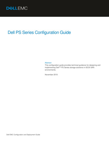
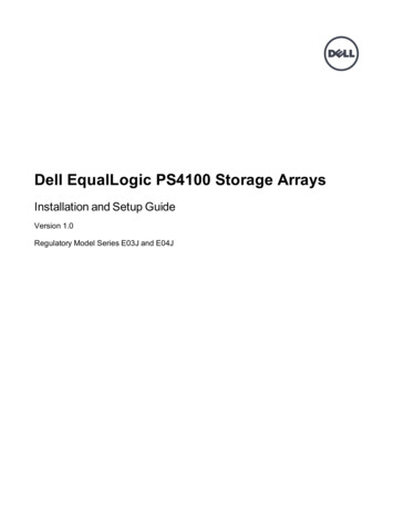
1 Basic Array InformationThis chapter includes basic information about PS3000 Series arrays: Array Front and Back Panels on page 1-1 Interpreting Operations Panel LEDs on page 1-2 Using an Electrostatic Wrist Strap on page 1-4 Shutting Down and Restarting an Array on page 1-4Array Front and Back PanelsThe front and back panels of a PS3000 Series array are shown below.Figure 1-1: PS3000 Series Front PanelFigure 1-2: PS3000 Series Back Panel1–1
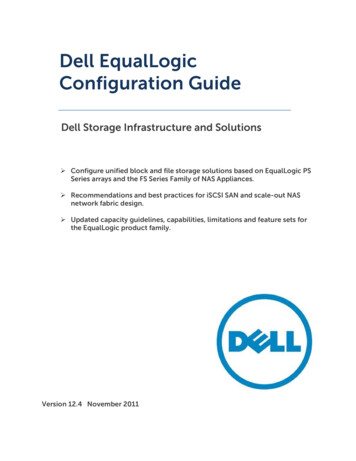
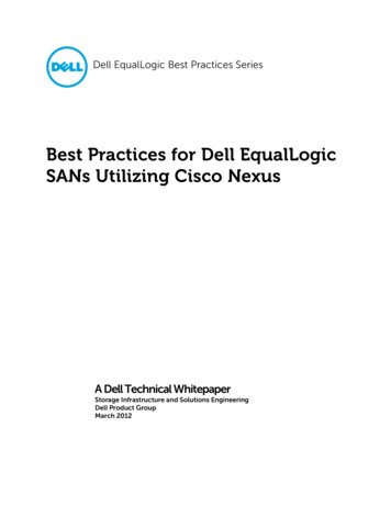
PS3000 Series Hardware MaintenanceBasic Array InformationInterpreting Operations Panel LEDsThe operations panel is used to monitor PS3000 Series hardware components. Thepanel is not redundant, but an array can continue to operate if it fails. See your PSSeries array service provider for information about servicing the panel.Figure 1-3 and Table 1-1 describe the LEDs on the PS3000 Series arrayoperations panel, which can alert you to errors and conditions that require yourattention. Serious problems should be reported to your PS Series service provider.For information about other LEDs, see Interpreting Disk LEDs on page 2-1,Interpreting Control Module LEDs on page 3-2, and Interpreting Power Supplyand Cooling Module LEDs on page 4-1.Figure 1-3: Operations Panel LEDsTable 1-1: Operations Panel LED DescriptionsOperations LEDColorDescriptionPower (upper right)OffNo power.GreenPower.Array locator (upper left) OffNo power or normal condition.Flashing Administrator enabled the array locator function.orange1–2
PS3000 Series Hardware MaintenanceBasic Array InformationTable 1-1: Operations Panel LED Descriptions (Continued)Operations LEDColorDescriptionWarning condition(lower left)OffNo power or normal condition.Error condition (lowerright)OffFlashing One or more of the following has occurred:orange RAID set is degraded but still functioning. RAID set (volume level) has lost blocks. Component temperature is near a limit. Fan failed or fan RPMs exceed limit. Power supply is not installed or has no power. Only one control module installed or controlmodule has failed over. Control module has insufficient RAM. Syncing active and secondary control modules. No communication between control modules. Installed spare disk does not have enoughcapacity to replace a disk in a RAID set. A non-critical hardware component failed. Real-time clock battery is low.No power or normal condition.Flashing One or more of the following has occurred:orange RAID is not functioning. Lost block table is full. Temperature exceeds upper or lower limit. Control module cache has lost data. A cooling module is not installed. Both fans on a cooling module have failed. Cache battery has less than 72 hours charge ortemperature is too high to charge battery. NVRAM coin cell battery failed. Cache contains data that does not belong to anyof the installed disks. More than one valid RAID set exists in array. Control modules are different models. A critical hardware component has failed. Operations panel failed or not installed. Storage enclosure processor that monitorsarray components has experienced a failure.1–3
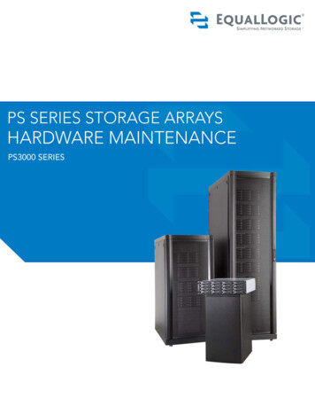
PS3000 Series Hardware MaintenanceBasic Array InformationUsing an Electrostatic Wrist StrapWhen handling the array chassis, disks, or control modules, you must use anelectrostatic protection device to prevent electrostatic discharge.An electrostatic wrist strap is included in the shipping box.Figure 1-4: Using an Electrostatic Wrist StrapShutting Down and Restarting an ArrayA PS3000 Series array includes redundant, hot-swappable disks, power supplies,and control modules (if a dual control module array). You can remove a redundantcomponent without affecting operation if a functioning component is available.Otherwise, it is recommended that you cleanly shut down the array and turn offpower before removing a component.Note: When an array is shut down, any volumes with data on the array will be setoffline until the array is successfully restarted. This may affect initiatorsthat are connected to the volumes.To shut down an array, follow these steps:1. Do one of the following:1–4 Use telnet or SSH to connect to a functioning IP address assigned to anetwork interface on the array. Do not connect to the group IP address. Use the null modem cable shipped with the array to connect Serial Port 0on the active control module (ACT LED is green) to a console or acomputer running a terminal emulator.
PS3000 Series Hardware MaintenanceBasic Array InformationSerial line characteristics are as follows:-9600 baudOne STOP bitNo parity8 data bitsNo hardware flow control2. Log in to an account with read-write access, such as the grpadmin account.3. Enter the shutdown command, as shown next.Login: grpadminPassword: xxxxxxxWelcome to Group ManagerCopyright 2001-2007 EqualLogic, Inc. shutdownIf you are using a serial connection to shut down an array, it is safe to turn offpower when the “press any key” message appears. (Pressing any key will restartboth control modules.)If you are using a network connection, the session will be disconnected before thearray is fully shut down. Confirm that the ACT LED on each control module is off(not lit) before turning off power to the array.After performing array maintenance, you can turn on power to the array. When thearray restart completes, the member and volumes will be set online.1–5
2 Maintaining DisksEach PS3000 Series array includes up to 16 hot-swappable disks. Diskmaintenance topics include: Interpreting Disk LEDs on page 2-1 Disk Handling Requirements on page 2-2 Identifying Failed Disks on page 2-3 Removing Disks on page 2-3 Installing Disks on page 2-5Interpreting Disk LEDsFigure 2-1shows how disks are numbered in a PS3000 Series array.Figure 2-1: PS3000 Series Disk NumberingFigure 2-2 shows the disk LEDs. Table 2-1 describes the LEDs.Figure 2-2: PS3000 Series Disk LEDs2–1
PS3000 Series Hardware MaintenanceMaintaining DisksTable 2-1: PS3000 Series Disk LED DescriptionsDisk LEDs ColorDescriptionTopOffNo power or error condition.GreenPower.Flashing greenDisk activity.OffNo power or normal condition.RedError condition.BottomDisk Handling RequirementsYou must adhere to the following disk handling requirements: Store disks properly. Store replacement disks in the packaging in which theywere shipped. Do not stack disks or place anything on top of a disk. Protect disks from electrostatic discharge. Wear an electrostatic wrist strapwhen handling a disk, unless it is protected from electrostatic discharge. Handle disks carefully. Hold a disk only by the plastic part of the carrier orthe handle. Do not drop or jolt a disk or force a disk into a disk slot. Warm replacement disks to room temperature before installation. Forexample, let a disk sit overnight before installing it in an array. Do not leave disk slots empty. Each disk slot in an array must contain a diskdrive assembly or a blank carrier. Operating an array with an empty disk slotwill void your warranty and support contract. Do not remove a disk from its carrier. This action will void your warrantyand support contract. Keep shipping material. Return a failed disk to your PS Series array serviceprovider in the packaging in which the replacement disk was shipped.Shipping disks in unauthorized packaging may void your warranty.2–2
PS3000 Series Hardware MaintenanceMaintaining DisksIdentifying Failed DisksDisks in a PS3000 Series array are numbered from 0 to 15 (from left to right, toprow to bottom row). A disk failure is indicated by: The disk’s error LED (bottom) is red, and the power LED (top) is off. SeeInterpreting Disk LEDs on page 2-1. A message on the console, in the event log, or in the Group Manager GUIAlarms panel describes a disk failure. The GUI Member Disks window or the CLI member select show diskscommand shows a disk failure.Handling Failed DisksHow an array handles a disk failure depends on whether a spare disk is availableand whether the RAIDset containing the failed disk is degraded. For example: If a spare disk is available, it replaces the failed disk. Performance is normalafter reconstruction completes. If a spare disk is not available and the failed disk is in a RAIDset with noprevious disk failure, the RAIDset becomes degraded. Performance may beimpaired. If a spare disk is not available and the failed disk is in a RAIDset that isalready degraded, data may be lost and must be recovered from a backup.Removing DisksBefore removing a disk or blank carrier from an array, attach an electrostaticprotection device, as described in Using an Electrostatic Wrist Strap on page 1-4.Notes: Replace a failed disk as soon as possible to ensure the highest availability.Do not remove a disk from a slot, unless you have another disk or a blankcarrier to replace it. Each slot must contain a disk or blank carrier.Do not remove a functioning disk from an array, unless the disk is a spare;otherwise, a RAIDset may become degraded. If you remove a spare,replace the disk as soon as possible.Before completely removing a functioning disk from an array slot, wait30 seconds to allow the disk to stop spinning and the heads to land.Store replacement disks in the packaging in which they were shipped.2–3
PS3000 Series Hardware MaintenanceMaintaining DisksFigure 2-3 shows how to remove a disk from a PS3000 Series array. Instructionsfor removing a blank carrier are similar, except you do not have to wait 30seconds.Figure 2-3: Removing a Disk2–4
PS3000 Series Hardware MaintenanceMaintaining DisksInstalling DisksBefore installing a disk or blank carrier in an array, attach an electrostaticprotection device, as described in Using an Electrostatic Wrist Strap on page 1-4.Notes: Install only disks of the same type, speed, and spin rate in an array. Thecolor of the handle release button indicates the disk type.You can use disks with different sizes in an array. However, the smallestdisk in the array will determine how much space can be used on each disk.For example, if the smallest disk is 400GB, only 400GB of space will beavailable for use on each disk.Be sure to insert a disk fully in the chassis before pushing in the handle.When correctly installed, the disk carrier should not protrude from thechassis. After installation, make sure the disk power LED (top) is green orflashing green.There is a two-minute delay between the time you insert a disk and thetime the disk is automatically configured into a RAIDset. This timeinterval allows multiple disks to be simultaneously configured in an array,which is more efficient than installing a single disk, configuring it, andthen repeating the process. For example, when you install a disk, the timerstarts. If no other disks are installed, the disk is configured after a delay oftwo minutes. If you install another disk before two minutes have elapsed,the timer is restarted.If you install a disk during RAID reconstruction or verification, the newdisk will not be configured until the operation completes.2–5
PS3000 Series Hardware MaintenanceMaintaining DisksFigure 2-4 shows how to install a disk in an array. Use the same instructions forinstalling a blank carrier.Notes: Make sure the disk is oriented in the position shown below, with thehandle release button to the left.When correctly installed, a disk will be level with the front of the array. Ifthe disk is protruding from the array, reinstall the disk.Figure 2-4: Installing a DiskVerify that the new disk is operational by checking the LEDs on the front panel, asdescribed in Interpreting Disk LEDs on page 2-1. The top LED should be green orflashing green, and the bottom LED should be off.In addition, the GUI Member Disks window and the CLI member select showdisks command output should show that the new disk is operational.2–6
3 Maintaining Control ModulesA PS3000 Series array includes one or two hot-swappable control modules. Eachcontrol module includes a field-replaceable compact flash card (running PS Seriesfirmware), in addition to cache and NVRAM batteries. For information aboutreplacing a cache or NVRAM battery, contact your PS Series service provider.Control module maintenance topics include: Supported Control Modules on page 3-1 Control Module Handling Requirements on page 3-3 Identifying Control Module Failures on page 3-3 Understanding Failover Behavior on page 3-3 Maintaining Control Module Firmware on page 3-4 Connecting Network Cables on page 3-5 Removing a Control Module on page 3-7 Installing a Control Module on page 3-9 Replacing the Compact Flash Card on page 3-11Supported Control ModulesAt the time of this release, PS3000 arrays support both Type 3 and Type 4 controlmodules, which are functionally equivalent and distinguished only by color.Always check the latest Release Notes for information about additional supportedcontrol modules.This manual shows arrays with Type 4 control modules (gray), but the informationalso applies to arrays with Type 3 control modules (blue). However, do not mixcontrol module types in an array.Figure 3-1: Type 3 Control Module (Blue)Figure 3-2: Type 4 Control Module (Gray)3–1
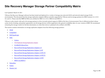
PS3000 Series Hardware MaintenanceMaintaining Control ModulesInterpreting Control Module LEDsControl modules have LEDs that enable you to determine the status of the controlmodule (active or secondary) and identify problems. In addition, each networkinterface on a control module also has LEDs.Figure 3-3: Control Module LEDsNote: Control modules are installed vertically in a PS3000 Series array, with thelatch mechanism facing the power supply and cooling module.Table 3-1: Control Module LED DescriptionsControl Module LEDsColorDescriptionACTOffNo power, secondary control module is notsynchronized with active control module, orerror condition.GreenActive control module (serving network I/O).OrangeSecondary control module; cache issynchronized with active control module.OffNo power or no error condition.RedArray is starting up or error condition.OffNo power.GreenPower.ERRPWRTable 3-2: Network Interface LED DescriptionsNetwork Interface LEDs ColorDescriptionLeft (as shown inFigure 3-3)OffNo power or not connected to network.GreenConnected to network.Right (as shown inFigure 3-3)OffNo power or not transmitting.GreenTransmitting.3–2
PS3000 Series Hardware MaintenanceMaintaining Control ModulesControl Module Handling RequirementsYou must adhere to the following control module handling requirements: Protect control modules from electrostatic discharge. Always wear anelectrostatic wrist strap when handling a control module, as described inUsing an Electrostatic Wrist Strap on page 1-4. When not installed, store acontrol module in an antistatic bag or place it on a surface protected fromelectrostatic discharge. Do not remove a control module from an array while the control modulesare synchronizing. When synchronization completes, a console message willappear. Also, the ACT LED on the secondary control module will be orange. Do not leave a control module slot empty. In an array with one controlmodule, always attach a blank face plate to the empty control module slot.Identifying Control Module FailuresA failure in a control module can be indicated by the following: A control module’s ERR LED is red or the PWR LED is off but there ispower to the array. See Interpreting Control Module LEDs on page 3-2. The ACT LED on one control module is green, but the ACT LED on the othercontrol module is off instead of orange. A message on the console, in the event log, or in the Group Manager GUIAlarms panel describes a control module failure. The GUI Member Controllers window or CLI member select showcontrollers command shows the control module as not installed.CM0 refers to the control module to the right, when viewing the array back panel.CM1 refers to the control module to the left.Understanding Failover BehaviorA PS3000 Series array can have one to three active network connections. In a dualcontrol module array, only one control module is active (serving network traffic)at one time. Each control module includes a battery-backed write cache for storingrecently-used data. For redundancy, the cache on the secondary control modulemirrors the data that is stored in the cache on the active control module.Each control module has three ports: Ethernet 0, Ethernet 1, and Ethernet 2. Theactive control module can use a network interface only if there is a cable3–3
PS3000 Series Hardware MaintenanceMaintaining Control Modulesconnected to the port on the active control module. Therefore, you should connecta cable to the network interface port on each control module to ensure that bothcontrol modules can access an interface.A PS3000 Series array provides two types of network failure protection: Network connection failover. If multiple network interfaces are configuredand one network interface fails, iSCSI initiators that were connected to thefailed interface can reconnect to the group IP address and be redirected to afunctioning interface. For example, in a single control module array, ifEthernet 0 and Ethernet 1 are connected to a network, and Ethernet 0 fails,initiators that were connected to Ethernet 0 can be redirected to Ethernet 1. Control module failover. In a dual control module array, if the active controlmodule fails, the secondary automatically takes over and becomes active. If acable is connected to the port on the newly active control module, network I/Ocan continue through that interface. Control module failover is transparent toapplications, but iSCSI initiators must reconnect to the group IP address.Maintaining Control Module FirmwareA PS3000 Series array includes one or two control modules, each with a compactflash card running the array firmware. You should run the latest firmware versionto take advantage of new product features and enhancements.Caution: In a dual control module array, both control modules must be runningthe same firmware version; otherwise, only one control module will befunctional. When you use the update command procedure, bothcontrol modules are updated to the same firmware version.Group members should run the same firmware version; otherwise, onlyfunctionality common to all versions will be available in the group. See thePS Series Release Notes for information about mixed-firmware groups.If you are upgrading to a dual control module array or replacing a failed compactflash card, be sure to order the correct firmware version from EqualLogic. If youare replacing a failed control module, remove the compact flash card from thefailed control module and install it in the replacement control module. This willensure that you retain the correct firmware.A new compact flash card will show the firmware version on the label. To displaythe firmware version running on an array, examine the GUI Member Controllerswindow or use the CLI member select show controllers command. If thefirmware on a compact flash card does not match the firmware running on anarray, do not install it. Instead, contact your PS Series array service provider.3–4
PS3000 Series Hardware MaintenanceMaintaining Control ModulesConnecting Network CablesA PS3000 Series array must have at least one and can have up to three activenetwork connections at one time. Multiple network connections are recommendedfor performance and availability.Connect cables to network interfaces as follows: For copper-based networks, use Category 5E or Category 6 cables with RJ45connectors. Use Category 5 cables if they meet the TIA/EIA TSB95 standard. Connect interfaces in this order: Ethernet 0, Ethernet 1, and Ethernet 2. Connect interfaces to different network switches. In a dual control module array, to ensure connectivi
Reference manuals and the Group Manager online help. In addition, the Host Integration Tools for Microsoft Windows systems are available on the Host Integration Tools CD -ROM that is shipped with the product. Technical support on EqualLogic products is available for customers with arrays under warranty and customers with a valid support .