Transcription
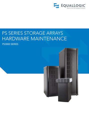
Dell EqualLogic PS4210 Storage ArraysHardware Owner's ManualVersion 1.0
Copyright 2014 Dell Inc. All rights reserved.Dell and EqualLogic are trademarks of Dell Inc. All trademarks and registered trademarks mentioned hereinare the property of their respective owners.Information in this document is subject to change without notice.Reproduction of this material in any manner whatsoever without the written permission of Dell is strictlyforbidden.Published: November 2014Part Number: 110-6215-EN-A01
Table of ContentsPreface1 Basic Storage Array InformationAbout the PS4210 ArrayRecommended ToolsProtecting HardwareBack-Panel Features and IndicatorsShutting Down and Restarting an Array2 Maintaining DrivesAbout Drive TypesIdentifying Failed DrivesInterpreting Drive LEDsArray Behavior When a Drive FailsDrive Handling RequirementsDrive Installation Guidelines and Restrictions3 Maintaining Control ModulesControl Module FeaturesReplacing a Control ModuleReplacing the MicroSD CardBattery ReplacementShipping RequirementsAdvanced Networking Options4 Maintaining Power Supply and Cooling ModulesAbout Power SuppliesIdentifying Power Supply Failures5 Troubleshooting Your i
Table of Contentsiv
PrefaceThis manual describes how to install Dell EqualLogic PS4210 storage array hardware, configure thesoftware, and start using the iSCSI SAN array.With one or more PS Series storage arrays, you can create a PS Series group—a self-managing, iSCSI storagearea network (SAN) that is affordable and easy to use, regardless of scale.AudienceThe information in this guide is intended for the administrators responsible for installing array hardware.Administrators are not required to have extensive network or storage system experience. However, it is helpfulto understand: Basic networking concepts Current network environment User disk storage requirements RAID configurations Disk storage managementAlthough this manual provides examples of using PS Series arrays in some common network configurations,detailed information about setting up a network is beyond its scope.Related DocumentationFor detailed information about FS Series appliances, PS Series arrays, groups, volumes, array software, and hostsoftware, log in to the Documentation page at the customer support site (eqlsupport.dell.com).Dell EqualLogic Storage SolutionsTo learn more about Dell EqualLogic products and new releases, visit the Dell EqualLogic Tech Center site:delltechcenter.com/page/EqualLogic. Here you can also see articles, demos, online discussions, and more detailsabout the benefits of our product family.Contacting DellDell provides several online and telephone-based support and service options. Availability varies by country andproduct, and some services might not be available in your area.To contact Dell EqualLogic Technical Support by phone, if you are located in the United States, call 800-9453355. For a listing of International Dell EqualLogic support numbers, visit dell.com/support/home. From thiswebsite, select your country from the drop-down list in the upper-left corner of the screen. If you do not haveaccess to an Internet connection, contact information is printed on your invoice, packing slip, bill, or Dell productcatalog.Use the following procedure to register for an EqualLogic customer support account, to log cases via the web,and to obtain software updates, further documentation, and resources.1. Visit eqlsupport.dell.com or the Dell support URL specified in information provided with the Dell product.2. Select the required service. Click the Contact Us link, or select the Dell support service from the list ofservices provided.3. Choose your preferred method of contacting Dell support, such as email or telephone.v
PrefaceOnline ServicesYou can learn about Dell products and services by visiting dell.com (or the URL specified in any Dell productinformation).Warranty InformationThe PS4210 array warranty is included in the shipping box. For information about registering a warranty, visitonlineregister.com/dell.Note, Caution, and Warning SymbolsA NOTE symbol indicates important information that helps you make better use of your hardware or software.A CAUTION symbol indicates potential damage to hardware or loss of data if instructions are not followed.A WARNING symbol indicates a potential for property damage, personal injury, or death.vi
1 Basic Storage Array InformationThis chapter includes information about the location and basic operation of the replaceable components in astorage array, tools and equipment you will need, protecting hardware from electrostatic discharge, and poweron and off operations.About the PS4210 ArrayThe PS4210 is a PS4x10 10GbE class EqualLogic PS Series array that continues the focus by Dell onindustry-standard features and capabilities for the midrange iSCSI SAN market.PS4210 FeaturesThe PS4210 array is available in a 2U chassis with up to 24 2.5-inch drives, or 12 3.5-inch drives.Features of the PS4210 array include: Two hot-swappable Type 19 control modules, which contain increased memory (8GB per controller) and amore powerful processor than previous generation controllers Ethernet ports:– Two pairs of 10Gb/s dual-media interfaces (10GBASE-T/SFP )– Ability to auto-negotiate down to 1Gb/s interface (10GBASE-T ports only) Support for ReadyRails IIRecommended ToolsYou will need the following items to perform the procedures in this section: Bezel key Wrist grounding strapProtecting HardwareProtect your PS Series array from electrostatic discharge. When handling array hardware, use an electrostaticwrist strap or a similar form of protection. To use a wrist strap:1. Connect the steel snap on the coil cord to the stud on the elastic band. See Figure 1.Figure 1: Using an Electrostatic Wrist Strap1
1 Basic Storage Array InformationPS4210 Hardware Owner's Manual2. Fit the band tightly around your wrist.3. Connect the band to ground. You can either plug the banana connector into a matching grounded receptacle,or attach it to the matching alligator clip and connect the clip to a grounded device. Examples of anappropriate ground would be an ESD mat or the metal frame of a grounded piece of equipment.Array BezelThe bezel is an optional trim panel that attaches to the front of the array to ensure the physical security of thearray. You must remove the bezel to access and maintain the drives.The bezel has a label that identifies the array model number.Removing the BezelThe steps for removing the bezel are the same for all array models:1. Using the bezel key, unlock the bezel.2. Holding the bezel, lift the latch on the left side of the bezel and swing the left side away from the array.3. Lift the right side of the bezel off the right side of the array.4. Set the bezel aside.Installing the BezelThe steps for installing the bezel are the same for all array models:1. Hook the right end of the bezel onto the right side of the chassis.2. Swing the left end of the bezel toward the left side of the chassis.3. Press the bezel into place until the release latch closes.4. Using the key provided, lock the bezel and store the key in a safe place as shown in Figure 2.Figure 2: Installing the Bezel2
PS4210 Hardware Owner's Manual1 Basic Storage Array InformationFront-Panel Features and IndicatorsThe front of a PS4210, without the bezel, is shown in Figure 3.Table 1 describes the front-panel features.Figure 3: Front-Panel Features and Indicators (3.5-inch Drives)Figure 4: Front Panel Features and Indicators (2.5-inch Drives)Table 1: Front-Panel Feature DescriptionsItem Indicator1Array statusLED2Power LED3Drive releaselatchIconNoneDescriptionThe array status LED lights when the array power is on. Off—No power. Steady blue—Array status is OK. Slow blinking blue—Array status is Standby mode. Blinking blue—Administrator request to identify the array (see the Group Manageronline help). Steady amber—Critical status. Blinking amber—Warning.The power LED is ON when at least one power supply is supplying power to the array. Off—No power, or the array is in Standby mode. Steady green—Array has at least one power supply providing power, and array isnot in Standby mode.Enables you to remove a drive from the array.The LEDs are part of a built-in chassis control panel that is not hot-swappable and can be replaced only bysupport personnel. During the array power-up sequence, these LEDs will cycle through different states until thearray is fully started and the active control module has been determined.3
1 Basic Storage Array InformationPS4210 Hardware Owner's ManualBack-Panel Features and IndicatorsThe back of a PS4210 is shown in Figure 5.Table 2 describes the back-panel features.Figure 5: Back-Panel FeaturesTable 2: Array Back-Panel FeaturesItemFeatureIdentifier1Power switchNone2Power supply unit PSU0 (left)(PSU)PSU1 (right)3Control moduleCM0 (top)CM1 (bottom)4Control modulerelease leverNoneDescriptionThe power switch controls the power supply output to the array. Oneswitch on each power supply.Power supply and cooling fan module for array.The control module provides: Connection to a data path between the array and the applicationsusing the storage Array management functions for your arrayEnables you to remove the control module from the array.Shutting Down and Restarting an ArrayA PS Series array includes redundant, hot-swappable drives, power supplies, and control modules (in a dualcontrol module array). You can remove a redundant component without affecting operation if a functioningcomponent is available. Otherwise, Dell recommends that you cleanly shut down the array and turn off powerbefore removing a component.When an array is shut down, any volumes with data on the array will be set offline until the array is successfullyrestarted. Being offline affects initiators that are connected to the volumes.Array shutdown procedure1. Connect to the array in one of the following ways:4
PS4210 Hardware Owner's Manual1 Basic Storage Array Information Use telnet or SSH to connect to a functioning IP address assigned to a network interface on the array.Do not connect to the group IP address. Use the null modem cable, shipped with the array, to connect the serial port on the active control module(ACT LED is green) to a console or a computer running a terminal emulator.Make sure the serial line characteristics are as follows: 9600 baud One STOP bit No parity 8 data bits No flow control2. Log in to an account with read-write access, such as the grpadmin account.3. Enter the shutdown command, as follows:login: grpadminPassword:Welcome to Group ManagerCopyright 2001-2014 Dell Inc.group1 shutdownIf you are using a serial connection to shut down an array, it is safe to turn off power when the “press any key”message appears. (Pressing any key will restart both control modules.)If you are using a network connection, the session will be disconnected before the array is fully shut down.Confirm that the ACT LED on each control module is off (not lit) before turning off power to the array.After performing array maintenance, you can turn on power to the array. When the array restart completes, themember and volumes will be set online.5
PS4210 Hardware Owner's Manual61 Basic Storage Array Information
2 Maintaining DrivesYou can replace a failed drive while the array remains running.About Drive TypesDepending on your configuration, your array supports up to 24 2.5-inch SAS and SSD drives or up to 12 3.5-inchSAS or NL-SAS drives in internal drive bays.Drives are connected to a backplane through drive carriers and are hot-swappable.Drives are supplied in a carrier that is keyed to fit into specific array models, and cannot be installed in otherDell arrays, or arrays not from Dell Inc.Dell uses specially qualified and tested hard drives for its EqualLogic storage systems, and manages hard drivequality and firmware only for those drives. As a result, only Dell-provided hard drives are supported by PS Seriesarrays. Attempts to use other, unapproved hard drives in the PS4210 array will not be successful.Identifying Failed DrivesA drive failure is indicated by:LEDs on the drive.A message on the console, in the event log, or in the Group Manager Alarms panel.Indications in the Group Manager Member Disks window or the CLI member select show disks commandoutput.Behind the bezel, arrays have a label showing the drive numbering for that specific array model: In arrays with 2.5-inch drives (installed vertically in a row), the drives are numbered 0–23, left to right. In arrays with 3.5-inch drives (installed horizontally), the drives are numbered from left to right and top tobottom, starting with 0 on the upper left side. Table 3 shows the drive order for the 3.5-inch drives.Table 3: 3.5-inch Drive Numbering0 1 234 5 678 9 10 11Interpreting Drive LEDsThe LEDs on a 3.5-inch drive are shown in Figure 6. The LEDs on a 2.5-inch drive are shown in Figure 7. DriveLED states are described in Table 4.7
2 Maintaining DrivesPS4210 Hardware Owner's ManualFigure 6: LEDs on 3.5-inch DrivesFigure 7: LEDs on 2.5-inch DrivesTable 4: Drive LED StatesDescriptionIndicator StatesDrive activity indicator (ACT LED)Blinking green: Drive is busySteady green: No drive activityOff: Drive is a spare, and spun downDrive status indicator (PWR LED)Green: Drive OKAmber: Drive failedOff: No power to driveArray Behavior When a Drive FailsIn firmware version 5.2.5 and later, Dell implemented a copy-to-spare operation to replace failing drives. Thisoperation can, in many cases, improve the performance of the drive replacement process by avoiding a fullRAID rebuild and as a result can provide better reliability.If a drive fails, replace it. Do not reinstall it in the array.8
PS4210 Hardware Owner's Manual2 Maintaining DrivesIf a Spare Drive Is Not AvailableIf a spare drive is not available, the RAID set will become degraded and performance might be impaired.However, a RAID 6 set can survive two simultaneous drive failures.If a spare drive is not available and the failed drive is in a RAID set that is already degraded, data might be lostand must be recovered from a backup.Drive Handling RequirementsHandle drives as follows: Protect drives from electrostatic discharge. Wear an electrostatic wrist strap when handling a drive. SeeProtecting Hardware on page 1. Store drives properly. Store replacement drives in the packaging in which they were shipped. Do not stackdrives or place anything on top of a drive. Handle drives carefully. Hold a drive only by the plastic part of the carrier or the handle. Do not drop, jolt,or force a drive into a slot. Warm replacement drives to room temperature before installation. For example, let a drive sit overnightbefore installing it in an array. Do not remove a functioning drive (other than a spare) from an array. If the drive is not a spare, the RAIDset might become degraded. If you remove a spare, replace the drive as soon as possible. Do not leave drive slots empty. Each drive slot in an array must contain a drive assembly or a blank carrier.Operating an array with an empty slot will void your warranty and support contract. Do not remove a drive from its carrier. This action will void your warranty and support contract. Keep the shipping material. Return a failed drive to your array support provider in the packaging in whichthe replacement drive was shipped. Shipping drives in unauthorized packaging might void your warranty.Drive Installation Guidelines and Restrictions Replace a failed drive as soon as possible, to provide the highest availability.Install only drives of the same type, speed, and spin rate in an array.You can use drives of different capacities in the same array. However, the smallest drive in the array willdetermine how much space can be used on each drive. For example, if the smallest drive is 400GB, only400GB of space will be available for use on each drive.Make sure the drive is oriented in the correct position for the array model. See Front-Panel Features andIndicators on page 3.Insert a drive fully in the chassis before pushing in the handle.When correctly installed, a drive will be flush with the front of the array. If the drive is protruding from thearray, reinstall the drive.After installation, make sure the drive power LED is green or flashing green. See Identifying Failed Driveson page 7.A two-minute delay occurs between the time you insert a drive and the time the drive is automaticallyconfigured into a RAID set. This time interval allows multiple drives to be simultaneously configured in anarray, which is more efficient than installing a single drive, configuring it, and then repeating the process.9
2 Maintaining DrivesPS4210 Hardware Owner's Manual For example, when you install a drive, the timer starts. If you install another drive before 2 minutes haveelapsed, the timer is restarted. If no other drives are installed, the drive is configured after a delay of 2 minutes.If you install a drive during RAID reconstruction or verification, the new drive will not be configured untilthe operation completes.Removing a 2.5-inch Drive1. Remove the bezel. See Removing the Bezel on page 2.2. Press the release button (callout 1 in Figure 8). The drive latch opens and the drive emerges partway fromthe array (callout 2).3. Pull the drive out by the handle until it is free of the drive bay (callout 3).Figure 8: Removing a 2.5-Inch Drive10
2 Maintaining DrivesPS4210 Hardware Owner's ManualInstalling a 2.5-inch DriveThe 2.5-inch drives are installed vertically, with the drive release latch on the top and the drive label on thebottom.1. Wear electrostatic protection when handling a drive. See Protecting Hardware on page 1.2. Open the drive release latch.3. Hold the drive by the carrier and slide the drive most of the way into a slot (callout 1 in Figure 9).4. Push the drive completely into the slot (callout 2). The drive handle will begin to close onto the drive (callout3).5. Push in the handle until you hear a click (callout 4).Figure 9: Installing a 2.5-inch Drive11
2 Maintaining DrivesPS4210 Hardware Owner's ManualVerify that the new drive is operational by examining the LEDs on the front panel, as described in InterpretingDrive LEDs on page 7. In addition, examine the GUI Member Disks window and the CLI member select showdisks command output.Removing a 3.5-inch Drive1. Remove the bezel. See Removing the Bezel on page 2.2. Press the release button (callout 1 in Figure 10). The drive latch opens and the drive emerges partway fromthe array (callout 2).3. Pull the drive out by the handle until it is free of the drive bay (callout 3).Figure 10: Removing a 3.5-Inch Drive12
2 Maintaining DrivesPS4210 Hardware Owner's ManualInstalling a 3.5-inch DriveThe 3.5-inch drives are installed horizontally, with the drive release latch to the left and the drive label to theright.1. Wear electrostatic protection when handling a drive. See Protecting Hardware on page 1.2. Open the drive release latch.3. Hold the drive by the carrier and slide the drive most of the way into a slot (callout 1 in Figure 11).4. Push the drive completely into the slot (callout 2). The drive handle will begin to close onto the drive (callout3).5. Push in the handle until you hear a click (callout 4).Figure 11: Installing a 3.5-inch Drive13
2 Maintaining DrivesPS4210 Hardware Owner's ManualVerify that the new drive is operational by examining the LEDs on the front panel, as described in InterpretingDrive LEDs on page 7. In addition, examine the GUI Member Disks window and the CLI member select showdisks command output.Removing a Drive BlankTo maintain proper system cooling, all empty drive slots must have drive blanks installed.1. Remove the bezel. See Removing the Bezel on page 2.2. Press the release tab and slide the drive blank out until it is free of the drive slot. See Figure 12 or Figure 13and the callouts in.Table 5.Figure 12: Removing and Installing a 3.5-Inch Hard-Drive BlankFigure 13: Removing and Installing a 2.5-Inch Hard-Drive BlankTable 5: Hard Drive Blank Callout ValuesItem12DescriptionDrive blankRelease tabInstalling a Drive Blank1. Remove the bezel. See Removing the Bezel on page 2.2. Insert the drive blank into the drive bay until the blank is fully seated.3. Attach the bezel.14
3 Maintaining Control ModulesDifferent PS Series array models contain different control module types. The combination of chassis type,control module pair, and drives determines the PS Series array model number.The control modules in a PS Series array contain the PS Series firmware, which provides the Group ManagerGUI, the command line interface, and all the array and storage management functions and features.Ideally, an array has two control modules (which must be of the same type) to avoid a single point of failure forthe array.A PS4210 array includes two hot-swappable Type 19 control modules.One functioning control module is required for array operation. You access control modules from the rear of thearray.Control Module FeaturesThe Type 19 control module includes: Two pairs of Ethernet ports with two shared LEDs indicating status and activity:– One pair of 10GBASE-T ports, labeled Ethernet 0 and Ethernet 1– One pair of SFP ports, labeled Ethernet 0 and Ethernet 1Only one of two ports with the same numbered port can be used at a time. If both ports are attached to anactive switch, the control module will prefer to communicate over the SFP interface. One 10Mb/100Mbps port, labeled MANAGEMENT, for use only if you configure a management network.The management port has two LEDs to indicate status and activity. See Configuring the Management Porton page 29 for more information.A column of LEDs labeled PWR (power), ERR (error condition) and ACT (activity) that indicate the statusof the control module.A recessed button labeled STANDBY ON/OFF that allows you to quickly shut down the array in certaincircumstances. See About the Standby On/Off Button on page 19 for more information.One serial port (for use if no network access to the array is available).A field-replaceable microSD card containing the PS Series firmware. The microSD card is accessed fromthe rear of the control module.A release button and latch to release the control module from the array for replacement. The release leverhas a switch that detects activation and prompts the array to save data to nonvolatile storage, therebyprotecting your data.Do not mix control module types in an array. Always make sure both control modules are the same type andcolor. See the latest PS Series Release Notes for information about other supported control modules.About Control Module ConfigurationsWhile an array can run using only one control module, it is not recommended because this configuration createsa single point of failure. If the control module fails and no other module can take over, all access to yourvolumes stops until the failure is repaired or the control module is replaced.15
PS4210 Hardware Owner's Manual3 Maintaining Control ModulesOnly one control module is active (providing disk access and serving network traffic) at one time. The secondary(redundant) control module mirrors cache data from the active control module. If the active control module fails,all functions of the primary controller transfer to the secondary.Dual Controller ConfigurationA dual control module configuration eliminates a single point of failure in the array. If the active control modulefails, the secondary control module takes over automatically with no interruption of service. This automatictransition gives you time to replace the failed control module while your volumes and data remain accessible.In addition, a dual control module configuration supports a feature called vertical failover. An Ethernet port onthe active control module can fail over to the same Ethernet port on the secondary control module if a networkpath fails. Figure 14 shows a recommended configuration for vertical failover.Figure 14: Recommended Network Configuration to Support Vertical Failover If a network port is available for failover on either control module, but is not currently in use, its LEDs willnot be lit.Vertical failover is transparent to applications.Interpreting Control Module LEDsControl modules have the following LEDs:16
3 Maintaining Control ModulesPS4210 Hardware Owner's Manual The Ethernet ports and the Management port each have LEDs that indicate the port's status and activity. SeeTable 6.Below the release latch is a column of three LEDs that indicate the status of the entire control module. SeeTable 7.Figure 15: Control Module LEDsTable 6: Ethernet and Management Port LED DescriptionsEthernet LEDLocationTop (Link)Bottom (Act)10GBASE-TEthernetLED LocationLeft (Link)Right (Act)SPF EthernetLED LocationTop (Link)Bottom (Act)ManagementLED LocationLeft (Link)Right (Act)StateDescriptionOffNo power or not connected to network.On (green)Connected to network.OffNo power, not transmitting, or not receiving.On (amber)Transmitting or receiving.StateDescriptionOffNo power, not connected to network, or passive.On (green)Connected to network.OffNo power, not transmitting, or not receiving.On (amber)Transmitting or receiving.StateDescriptionOffNo power, not connected to network, or passive.On (green)Connected to network.OffNo power, not transmitting, or not receiving.On (amber)Transmitting or receiving.StateDescriptionOffNo power or not connected to network.On (green)Connected to network (100mbit).On (amber)Connected to network (10mbit).OffNo power, not transmitting, or not receiving.On (blinking green)Transmitting or receiving.17
PS4210 Hardware Owner's Manual3 Maintaining Control ModulesTable 7: Control Module Status LED DescriptionsLED NamePWRERRACTStateOffDescriptionNo power.On (steadygreen)Power/OK.OffNormal operation or no power.Steady redArray is starting up, in error condition, in Standby mode, or returning from Standbymode.Blinking redArray is entering power standby mode because the Standby On/Off button waspressed.OffNo power, secondary control module is not synchronized with active control module,or error condition.Steady greenActive control module (serving network I/O).Steady amberSecondary control module. Cache is synchronized with active control module.Identifying Control Module FailuresYou can identify a failure in a control module by: LEDs on the control module itself. See Interpreting Drive LEDs on page 7. Messages on the console, in the event log, or in the Group Manager GUI Alarms panel. Group Manager GUI and CLI output. The Member Controllers window or the member select showcontrollers command output shows the control module status not installed.When viewed from the rear of the array, CM0 is on the top and CM1 is on the bottom. See Front-Panel Featuresand Indicators on page 3.If a control module fails, contact your PS Series support provider for a replacement.Understanding Failover BehaviorIn a dual control module array, only one control module is active (processing network I/O and performing storagefunctions) at one time. Each control module stores recently used data.For redundancy, the cache on the secondary control module mirrors the data that is stored in the cache on theactive control module.The active control module can use the network interfaces of the secondary control module for failover if a cableis connected from the corresponding port on the secondary control module to a functioning network switch.The management ports on the control modules do not fail over if one control module fails. Therefore, if you areusing a dedicated management network, make sure the management ports on both control modules areconnected to the management network.A PS Series array provides the following types of network failure protection: Vertical failover. In a dual control module array, a network port on the active control module can fail over tothe same network port on the other (secondary) control module if a network path fails. For example, ifEthernet 0 on CM0 loses connectivity (switch 0 fails), Ethernet 0 on CM1 cache is enabled and utilized. SeeDual Controller Configuration on page 16 for details. Control module failover. In a dual control module array, if the active control module fails, the secondarycontrol module automatically takes over and becomes active.18
PS4210 Hardware Owner's Manual3 Maintaining Control ModulesIf a cable is connected to a network port on the newly active control module, network I/O can switch to itsnetwork interface. Depending on circumstances, network I/O might instead continue through the previouslyactive control module. (For example, the control module that becomes active can use either its own local network interface, or the network interface on the previously active control module.)Control module failover occurs automatically, and if iSCSI initiators reconnect to the group IP address, application I/O can continue without user intervention.Maintaining Control Module FirmwareA Type 19 control module has a microSD card running the array firmware. You should run the latest firmwareversion to take advantage of new product features and enhancements.In a dual control module array, both control modules must be running the same firmware version; otherwise, onlyone control module will be functional. You must update the controller with the older version firmware to thesame version as the active before you update the member to a later version.Group members should run the same firmware version; otherwise, only the functionality common to all versionswill be available in the group. See the PS Series Release Notes for information about mixed-firmware groups.If you are replacing a failed control module, remove the microSD card from the failed control module and installit in the replacement control modu
This manual describes how to install Dell EqualLogic PS4210 storage array hardware, configure the software, and start using the iSCSI SAN array. With one or more PS Series storage arrays, you can create a PS Series group—a self-managing, iSCSI storage area network (SAN) that is affordable and easy to use, regardless of scale. Audience