Transcription
Dell EqualLogic PS4100 Storage ArraysInstallation and Setup GuideVersion 1.0Regulatory Model Series E03J and E04J
Copyright 2013 Dell Inc. All rights reserved.Dell and EqualLogic are trademarks of Dell Inc.All trademarks and registered trademarks mentioned herein are the property of their respective owners.Information in this document is subject to change without notice.Reproduction of this material in any manner whatsoever without the written permission of Dell is strictly forbidden.Published: May 2013Part Number: FW4G8-EN-A00
Table of ContentsPreface1 Understanding the Array Installation Procedure2 Rack Mounting the ArrayBefore You BeginProtecting HardwareSteps for Mounting an Array in a Rack3 Connecting the Array CablesNetwork Requirements and RecommendationsMinimum and Recommended Cable ConfigurationsConnect the Array to the NetworkSet Up a Serial Connection to the Array4 Software ConfigurationChoose a Configuration MethodCollect Configuration InformationStart the Software ConfigurationSet the Member RAID Policy5 Storage AllocationCreate a VolumeConnect a Computer to a Volume6 Where to Go After Setting Up a GroupCommon Group Customization Tasks7 Other Information You May NeedNOM Information (Mexico iii
Installation and Setup GuideivTable of Contents
PrefaceThis manual describes how to install Dell EqualLogic PS4100 storage array hardware, configure thesoftware, and start using the iSCSI SAN array.With one or more PS Series storage arrays, you can create a PS Series group—a self-managing, iSCSI storagearea network (SAN) that is affordable and easy to use, regardless of scale.AudienceThe information in this guide is intended for the administrators responsible for installing array hardware.Administrators are not required to have extensive network or storage system experience. However, it is helpfulto understand: Basic networking conceptsCurrent network environmentUser disk storage requirementsRAID configurationsDisk storage managementNote: Although this manual provides examples of using PS Series arrays in some common networkconfigurations, detailed information about setting up a network is beyond its scope.OrganizationThis manual is organized as follows: Chapter 1, Understanding the Array Installation Procedure describes the general steps for installing andsetting up an array. Chapter 2, Rack Mounting the Array describes how to install the array in a rack. Chapter 3, Connecting the Array Cables describes the network cable requirements and how to install thepower and network cables. Chapter 4, Software Configuration describes how to initialize the array and either create a group with thearray as the first member, or add the array to an existing group. Chapter 5, Storage Allocation describes how to create and connect to a volume. Chapter 6, Where to Go After Setting Up a Group describes basic and advanced group administration tasksand where to find information about them.Technical Support and Customer ServiceDell’s support service is available to answer your questions about PS Series SAN arrays. If you have an ExpressService Code, have it ready when you call. The code helps Dell’s automated-support telephone system directyour call more efficiently.Contacting DellDell provides several online and telephone-based support and service options. Availability varies by country andproduct, and some services might not be available in your area.v
Installation and Setup GuidePrefaceFor customers in the United States, call 800-945-3355. For a listing of International Dell EqualLogic supportnumbers, visit support.dell.com/global.Note: If you do not have access to an Internet connection, contact information is printed on your invoice,packing slip, bill, or Dell product catalog.Use the following procedure to contact Dell for sales, technical support, or customer service issues:1. Visit support.dell.com or the Dell support URL specified in information provided with the Dell product.2. Select your locale. Use the locale menu or click on the link that specifies your country or region.3. Select the required service. Click the “Contact Us” link, or select the Dell support service from the list ofservices provided.4. Choose your preferred method of contacting Dell support, such as e-mail or telephone.Online ServicesYou can learn about Dell products and services using the following procedure:1. Visit www.dell.com (or the URL specified in any Dell product information).2. Use the locale menu or click on the link that specifies your country or region.Warranty InformationThe PS4100 array warranty is included in the shipping box. For information about registering a warranty, visitwww.onlineregister.com/dell.Further InformationFor basic storage array information, maintenance information, and troubleshooting information, refer to theHardware Owner's Manual for your PS Series hardware.vi
1 Understanding the Array Installation ProcedureTo set up your array and start using the iSCSI SAN array, follow these steps:1. Install the array in a rack. See Rack Mounting the Array on page 3.2. Connect the array to power and the network. See Connect and Secure the Power Cables on page 1 andConnect the Array to the Network on page 10.3. Configure the PS Series software. First, initialize an array to make it accessible on the network. Then, eithercreate a group with the array as the first group member or add the array to an existing group. When youexpand a group, capacity and performance increase automatically. See Choose a Configuration Method onpage 15.4. Start using the iSCSI SAN array. Allocate group storage space to users and applications by creatingvolumes. A volume appears on the network as an iSCSI target. Use a computer’s iSCSI initiator to connectto a volume. Once you connect to a volume, it appears as a regular disk on the computer. See StorageAllocation on page 21.After getting started, you can customize the group and use its more advanced features. See Where to Go AfterSetting Up a Group on page 27.1
Installation and Setup Guide21 Understanding the Array Installation Procedure
2 Rack Mounting the ArrayFor proper operation, a PS Series storage array must be properly installed in a rack. This section containsgeneral electrostatic, safety, network, and installation information for PS Series arrays.After installing the array in a rack, connect the power and network cables, as described in Chapter 3.Before You BeginBefore installing the array: Read the installation safety precautions. See Installation Safety Precautions on page 3. Make sure the rack meets the rack requirements. See Rack Requirements on page 3.Make sure the array and installation location meet the environmental requirements. See EnvironmentalRequirements on page 4.Unpack the rail kit (if ordered) and make sure you have all the necessary parts and tools. The rail kit islocated in the array shipping box. You must supply your own tools. See Shipping Box Contents and RequiredHardware on page 4.Installation Safety PrecautionsFollow these safety precautions: Dell recommends that only individuals with rack mounting experience install an array in a rack. Make sure the array is fully grounded at all times to prevent damage from electrostatic discharge. When handling the array hardware, you must use the electrostatic wrist guard shipped with the array or asimilar form of protection. You need at least two people to lift the array chassis from the shipping box.Rack RequirementsThe rack and the array installation must meet the following requirements: Use an industry standard, EIA-310-D compliant, four-post 19 inch rack with universal square hole orunthreaded round hole spacing. The rack is rated for 540 kg (1200 pounds) static load or greater. The minimum rack depth is 100 cm (40 inches) from the front of the rack to the rear of the rack. For the ReadyRails II rail kits, the distance between the outside surfaces of the front and rear rack posts(the mounting surfaces) can range from 595 mm to 914 mm (23.4” to 36.0”) for square-hole racks, 581 mm to907 mm (22.9” to 35.7”) for round-hole racks and 595 mm to 929 mm (23.4” to 36.6”) for threaded-holeracks.The rack is secured to the floor for added stability. Load a rack with arrays from the bottom to the top.There is at least 4.1 cm (1.6 inches) between the rack door and the front of the array to accommodate thearray front bezel. The rack (with installed arrays) meets the safety requirements of UL 60950-1 and IEC 60950-1, available athttp://ulstandards.3
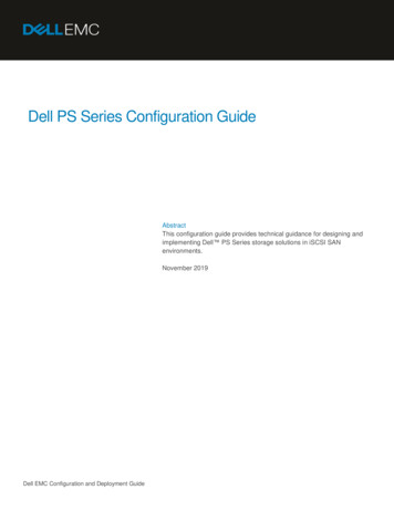
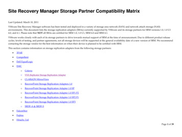
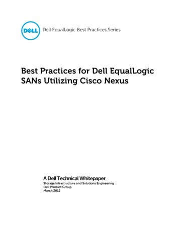
2 Rack Mounting the ArrayInstallation and Setup Guide Mount the array in a horizontal orientation, or you will void your array warranty and support contract.Environmental RequirementsThe rack location must meet the following environmental requirements: The power source can supply a voltage range of 100V to 240V AC. The power source has sufficient electrical overload protection:In North America, connect the array to a source of power with over-current protection provided by adouble pole 20A or less device (UL 489 circuit breakers).In Europe, the over-current protection must be provided by a 20A or less device (IEC circuit breakers). There is sufficient space for air flow in front of and behind the array.The location is properly vented.Your environment supports all of the requirements listed in the Technical Specifications on page 29.Protecting HardwareProtect your PS Series array from electrostatic discharge. When handling array hardware, use an electrostaticwrist strap or a similar form of protection. To use a wrist strap:1. Connect the steel snap on the coil cord to the stud on the elastic band. See Figure 1.Figure 1: Using an Electrostatic Wrist Strap2. Fit the band tightly around your wrist.3. Connect the band to ground. You can either plug the banana connector into a matching grounded receptacle,or attach it to the matching alligator clip and connect the clip to a grounded device. Examples of anappropriate ground would be an ESD mat, or the metal frame of a grounded piece of equipment.Shipping Box Contents and Required HardwareMake sure you have all the items supplied in the shipping box, described in Table 1. You must provide additionalhardware that is specific to your environment and not included in the shipping box. See Table 2.4
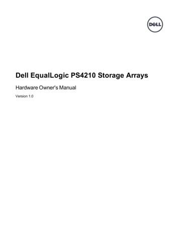
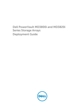
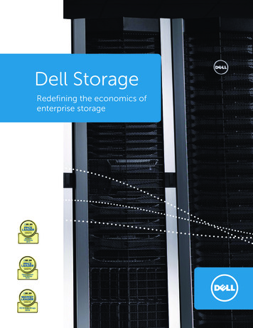
Installation and Setup Guide2 Rack Mounting the Array1. Determine where to place the mounting rails in the rack.2. Attach the mounting rails to the rack.3. Slide the chassis into the rack.4. Attach the chassis to the front of the mounting rails.5. Install the bezel.These steps are described in detail in the following sections.Determine Where to Place the Mounting Rails in the RackMake sure there is enough space in the rack for the chassis. In a standard rack, a 2U chassis will span six holes.Installing the Rails and Array in a RackInstall the rails in the rack following the safety instructions and the rack installation instructions provided withyour rail kit.If installed in a closed or multi-unit rack assembly, the operating ambient temperature of the rack environmentmay be greater than room ambient. Therefore, make sure you install the equipment in an environment compatiblewith the maximum ambient temperature (Tma) specified by the manufacturer. For more information, seeTechnical Specifications on page 29.Slide the Chassis into the RackFigure 2 shows the front view of the 3.5-inch drive array.Figure 2: 3.5-Inch Drive Array - Front View (without Bezel)Figure 3 shows the front view of the 2.5-inch drive array.Figure 3: 2.5-Inch Drive Array - Front View (without Bezel)Caution: Be careful when lifting the chassis.With assistance, lift the chassis and slide it onto the mounting rails. Keep the chassis level.Attach the Chassis to the Mounting RailsMake sure the chassis captive fasteners on the front of the array line up with the threaded holes on the front ofthe mounting rails, and manually secure the captive fasteners to the rails.Caution: Do not use an automatic driver to tighten the thumbscrews.6
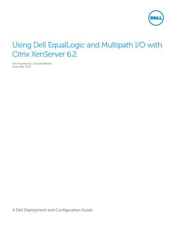
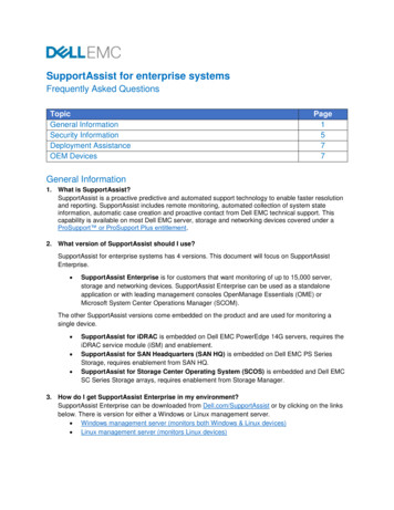
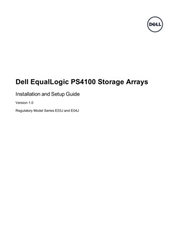
Installation and Setup Guide2 Rack Mounting the ArrayInstalling the BezelThe steps for installing the bezel are the same for all array models.1. Hook the right end of the bezel onto the right side of the chassis.2. Swing the left end of the bezel towards the left side of the chassis.3. Press the bezel into place until the release latch closes.4. Using the key provided, lock the bezel and store the key in a safe place.Figure 4: Installing the Bezel7
Installation and Setup Guide82 Rack Mounting the Array
Installation and Setup Guide143 Connecting the Array Cables
Installation and Setup Guide4 Software ConfigurationNote: If the array does not respond, contact your PS Series support provider for information on how toproceed.2. At the login prompt, enter grpadmin for both the account (login) name and the password. Passwords do notappear on the screen.3. When prompted, enter y to start the setup utility.4. When prompted, enter the array and group configuration information from Collect Configuration Informationon page 15. Press the Enter key to accept a default value. Enter a question mark (?) to get help.Note: There may be a short delay after entering the group IP address as the array searches the network.After setup completes, you must set the member’s RAID policy in order to use the disk storage. Go to Set theMember RAID Policy on page 18.The following example shows using the setup utility to initialize an array and create a group.EXAMPLE - Using the setup UtilityLogin: grpadminPassword: xxxxxxxxThe setup utility establishes the initial network and storage configuration for a storage arrayand then configures the arrayas a member or a new or existing group of arrays.For help, enter a question mark (?) at a prompt.Welcome to Group ManagerCopyright 2013 Dell Inc.It appears that the storage array has not been configured.Would you like to configure the array now? (y/n) [n] yGroup Manager Setup UtilityDo you want to proceed (yes no) [no]? yesInitializing. This may take several minutes to complete.Enter the network configuration for the array:Member name []: member1Network interface [eth0]: eth0IP address for network interface []: 192.17.2.41Netmask [255.255.255.0]:Default gateway [192.17.2.1]:Enter the name and IP address of the group that the array will join.Group name []: group1Group IP address []: 192.17.2.20Searching to see if the group exists. This may take a few minutes.The group does not exist or currently cannot be reached. Make sure you have entered the correctgroup IP address and group name.Do you want to create a new group (yes no) [yes]? yesGroup ConfigurationGroup Name: group1Group IP address: 192.17.2.20Do you want to use the group settings shown above (yes no) [yes]: yesPassword for managing group membership:Retype password for verification:Password for the default group administration account:Retype password for verification:17
Installation and Setup Guide4 Software ConfigurationSaving the configuration .Waiting for configuration to become active.DoneGroup member member1 now active in the group.Group group1 has been created with one member.Use the Group Manager GUI or CLI to set the RAID policy for the member. You can then create avolume that a host can connect to using an iSCSI initiator.group1 Using the Remote Setup Wizard to Configure the SoftwareThe Remote Setup wizard is located on the Host Integration Tools CD-ROM and must be installed on aWindows computer. The Host Integration Tools User Guide provides detailed information about using the fullcapabilities of the Remote Setup Wizard.To run the Remote Setup Wizard, follow these steps:1. Use a computer that meets the requirements in Choose a Configuration Method on page 15.2. Obtain the Host Integration Tools CD-ROM from the shipping box, or download the Host Integration Toolskit from the support website.3. Install the Remote Setup Wizard following the instructions in the Host Integration Tools documentation.4. Start the Remote Setup Wizard by clicking:Start, Programs, EqualLogic, Remote Setup Wizard5. In the Welcome dialog box, select Initialize a PS Series array and click Next.Note: If you cannot contact the array, check the network configuration. You may need to use the setuputility to configure the software.6. Select the array that you want to initialize and click Next.7. In the Initialize Array dialog box, enter the array configuration from Table 6 and choose to create a group orjoin an existing group. Then, click Next.8. In the Create a New Group or Join an Existing Group dialog box, enter the group configuration from Table 7and click Next.9. Click Finish to exit the wizard.If you added the array to an existing group, you must set the member’s RAID policy in order to use the diskstorage. Go to Set the Member RAID Policy on page 18.If you created a new group, go to Chapter 5, Storage Allocation.Set the Member RAID PolicyThe storage space in a new group member (array) is not available until you configure a RAID policy on themember.A RAID policy consists of a RAID level and a spare disk configuration. When you select a RAID policy, themember’s disks are automatically configured with the selected RAID level and the appropriate number of sparedisks.If you used the Remote Setup Wizard to create a group, the RAID policy for the first member is set according toyour RAID policy selection when configuring the software, and the storage is ready to use. See StorageAllocation on page 21.18
Installation and Setup Guide4 Software ConfigurationIf you used the setup utility to create or expand a group, or added the array to an existing group with the RemoteSetup Wizard, you must set the RAID policy for the group member.Use either the Group Manager command line interface (CLI) or the graphical user interface (GUI) to set theRAID policy.Using the CLI to Set the RAID PolicyTo use the Group Manager CLI to set the RAID policy for a new group member:1. Log in to the group, if you are not already logged in. (After the setup utility completes, you will still belogged in to the group.) Use one of the following methods to connect to the group:– Serial connection to a member. See Set Up a Serial Connection to the Array on page 11.– Telnet or ssh connection to the group IP address.2. At the login prompt, enter the grpadmin account name and the password that you specified when creating thegroup.3. At the Group Manager command prompt, enter the following command, to specify RAID6, , RAID10, orRAID50 for the policy variable:member select member name raid-policy policyFor example, the following command configures member1 with RAID6:member select member1 raid-policy raid6Using the Group Manager GUI to Set the RAID PolicyFor the latest information on browser support for the Group Manager GUI, see the PS Series Release Notes.After you add a member to a PS Series group, you must set the RAID policy for the member and choose thestorage pool. The storage in the member is available after you set the RAID policy.To use the GUI to set the RAID policy for a member:Procedure1. Click Group and then click the group name to open the Group Summary window.2. Expand Members and then double-click the member name. The GUI shows whether a member is configuredor not.3. Click Yes in the warning dialog to open The Configure Member – General Settings dialog.4. Select the pool and click Next. If prompted, confirm you want to assign the member to the pool.5. Select the RAID policy on the Configure Member – RAID Configuration dialog.6. [Optional] Select Wait until the member storage initialization completes.7. Click Next.8. Click Finish in the Configure Member – Summary dialog.Note: After initial RAID configuration, it takes a few minutes for the Group Manager to display the total usablecapacity. The Group Manager might show a smaller amount until the process is complete.19
Installation and Setup Guide204 Software Configuration
Installation and Setup Guide5 Storage Allocation– Using the GUI, expand Volumes in the far-left panel, select the volume name, and click the Access tab.If necessary, use the CLI or the GUI to create an access control record that the computer will match.3. To display the iSCSI target name for the volume:–Using the CLI, enter the following command:–Using the GUI, expand Volumes in the far-left panel, select the volume name, and click the Connectionstab.volume select volume name show4. On the computer, use the iSCSI initiator utility to specify the group IP address as the iSCSI discoveryaddress. If the initiator supports the discovery process, it will return a list of iSCSI targets that the computercan access.If the initiator does not support discovery, you must also specify the target name, and, in some cases, thestandard iSCSI port number (3260).5. Use the iSCSI initiator utility to select the desired target and log in to the target.When the computer connects to the iSCSI target, it sees the volume as a regular disk that can be formatted usingthe normal operating system utilities. For example, you can partition the disk and create a file system.26
IndexGAaccess control recordscreating 22access controlssetting up with CLI 21accountsconfiguring after setup 27arraychoosing where to mount 6initializing 15mounting in rack 6network address 15RAID policy 18software configuration 15groupaccessing volumes from a computer 26advanced tasks 27creating 15customizing after setup 27expanding 15IP address 16logging in to CLI 19logging in to GUI 19name 16GUIsetting RAID policy 18-19HhardwareBbezelrequirements 4supplied 5Host Integration Toolsinstalling 7description 18hostsCFlow Control recommendation 10Jumbo Frames recommendation 10cablesEthernet 5ICHAP accountsconfiguring 28initiator (iSCSI)CLIcreating volumes 21setting RAID policy 18-19connecting the serial cable 11control modules 5accessing a volume 26computer requirements 26installation safety precautions 3installingfront bezel 7iSNSDconfiguring 28dateJsetting 28Jumbo Frames recommendation 10Eelectrostatic discharge 4electrostatic wrist strap 4environmental requirements 4event notificationLloginCLI method 19GUI method 19configuring 28FMmanagement network switch 5Flow Control recommendation 1031
Index: member – volumesRemote Setup Wizardmemberdefault gateway 15naming 15netmask 15network address 15RAID policy 18configuring the software 18Ssafety precautionsinstallation 3Nserial cablecharacteristics 12connecting 11pin locations 12pinout information 12netmaskmember setting 15networkarray IP address 15configuring multiple interfaces 27group IP address 16improving performance 9recommendations 9requirements 9network interfacessetup utilityconfiguring the software 16description 15requirements 15shipping box contents 4snapshotsreserving space 21SNMPconfiguring 15NTP serverconfiguring 28software configurationconfiguring 28methods 15Ooptional hardware 5Spanning-Tree recommendation 10supplied hardware 5switchfor management only 5switchesPpowerturning on 11power requirements 4PS Series arrayincreasing bandwidth 9network recommendations 9network requirements 9protecting from discharge 4subnet access recommendation 9Rrack mountchoosing rail location 6inserting chassis 6installing chassis 6rail kit parts 5requirements 3RAID levelssupported 18RAID policydescription 18setting with CLI 19setting with GUI 193210/100Mbps 5bandwidth requirement 10Flow Control recommendation 10Jumbo Frames recommendation 10link recommendation 10Spanning-Tree recommendation 10Ttarget (iSCSI)connecting to 26obtaining name 26technical specifications 4thin provisioningenabling on a volume 21time, setting 28Vvolumesaccess control recordscreating 22access controls 22accessing from a computer 26connecting to 25
Index: warranty – warrantycreating 21creating standard 22creating with CLI 21naming 21reported size 21snapshot space 21target name for 26thin provisioning settings 21Wwarranty 2933
Dell's support service is available to answer your questions about PS Series SAN arrays. If you have an Express Service Code, have it ready when you call. The code helps Dell's automated-support telephone system direct your call more efficiently. Contacting Dell. Dell provides several online and telephone-based support and service options.