Transcription
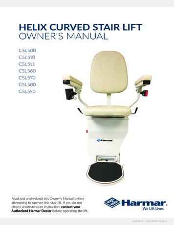
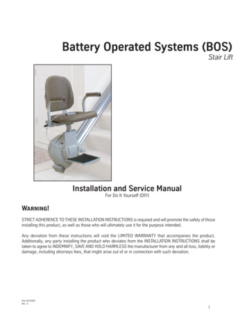
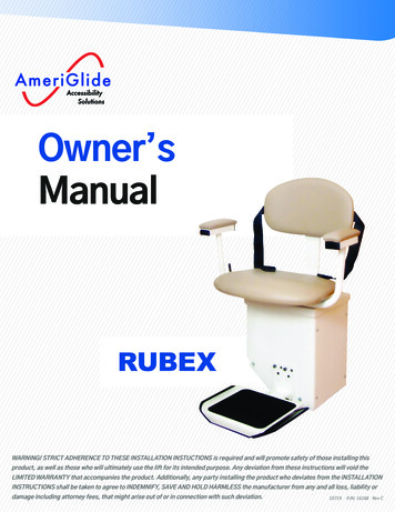
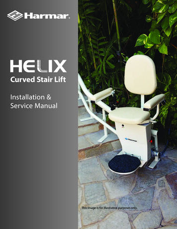
Curved Stair LiftInstallation &Service ManualThis image is for illustrative purposes only.TEC0067 P/N: 630-00063-01 Rev BHelix Curved Stair Lift - Install and Service Manual 20161
CONTENTSTABLE OF CONTENTS2WHATS IN THE BOX3REQUIRED TOOLS4INSTALLATION5-13FINAL CHECKS14TECHNIAL SPECIFICATIONS15WIRING16MAINTENANCESYMBOLS USED IN THIS MANUALREAD MANUAL - Pay close attention tothe instructions in the manual.CAUTION - Hazardous situation. If notavoided, could result in serious damageto property.WARNING - Hazardous situation. If notavoided, could result in serious injuryto installer or user.17-18HEAVY - Be sure to have help availableto avoid back injury.TIP - Helpful tips that will facilitate easeof installation.CHECK - Reminder to check certainportions of installation beforecontinuing.This manual provides instructions for properinstallation of this Curved Stair Lift. Pleaserefer to the Owner’s Manual for operatinginstructions. Be sure to provide the Owner’s Manualto the owner of the lift before it is put into service.Any alterations to the equipment without writtenauthorization by the manufacturer may void thewarranty.Lifts shall be installed so that means of egress ismaintained as required by the authority havingjurisdiction. 7.1.1Our lifts are designed to install with as littleassembly as possible. If you have questions,concerns or comments, please contact Harmar’sTechnical Service Department at 1-866-378-6848 oremail tech@harmar.com.Foot Rest Clearance. At no point in its travel shallthe edge of the footrest facing the upper landingbe more than 24 inches (610 mm) above the step orlanding as measured vertically.Device Name: Harmar Helix Curved Stair LiftIndications for Use: The intended use of the HelixStair Lift is to assist transfers of patients or mobilityimpaired persons up and down flights of stairs.2The structure which equipment is installed shall becapable of supporting the loads imposed. 7.1.2The installation of electrical equipment and wiringshall conform to the requirements of NFPA70 7.6.4ASME A18.1-2014 "SAFETY STANDARD FORPLATFORM LIFTS AND STAIRWAY CHAIR LIFTS" www.harmar.com 800-833-0478 2018 Harmar Mobility, LLC All Rights Reserved
WHAT'S IN THE BOXBox ContentsBefore beginning installation, please check the Curved Stair Lift contents and ensure that all componentsare complete and undamaged. Also check the enclosed illustration to verify specific parts since each liftis customized to the application. Report missing parts or shipping damage to your dealer or the shippingcompany.Contents Legs Rails Complete Seat Assembly and chassis Power Supply Wires Bag of Screws Pipe and Support Caps Charge StationTEC0067 P/N: 630-00063-01 Rev BHelix Curved Stair Lift - Install and Service Manual 20163
REQUIRED TOOLSThe tools required for installation of the lift willbe referenced throughout the manual. Eachpage will have a tool icon area at the top to helpdetermine which tools will be needed duringthat part of the installation.Mirror for checking chargerDrillAssorted Drill BitsAllen WrenchesEmery/SandpaperTowels (for cleaning)Lightweight grease (white lithium)Wire Stripper/CrimperFish TapeDrill Extention BitShimsRecommended: Volt OHM MeterOptional: Pull Strap/Ratcheting StrapTape MeasureMounting Screws could be needed,based on flooring (not shown)Angle Meter4 www.harmar.com 800-833-0478 2018 Harmar Mobility, LLC All Rights Reserved
INSTALLATIONHarmar’s Curved Stair Lift is easy to install. The standard installationwill normally take two installers approximately three hours. The timewill vary depending on the complexity of the lift ordered and customdesigns.1. Review Installation Drawing The dimensions on the drawingshow numbers on the stairs. These numbers indicate the positionof the supports.2. Carry chair/chassis to the location of the installation. Usuallytop of stairs. It's best to be a flat section of rail.Figure 5-1IMPORTANT - Do NOT lay chair on its back.WIRING NOTE: You may complete the wiring while puttingthe rail together or use a fish tape on the completed unitto run the wire.3. Position Stair Supports Place on the stair based on theinstallation drawing but do not bolt anything down at this point.[Figure 5-1]Figure 5-24. Assemble the Rail Place the rail in the correct position beginningwith the first section downstairs. Unwrap the rail, checking thelabel for order of placement on stairs. [Figures 5-2, 5-3]Follow the drawing included with the rail system.Run a wire through the lower rail. There is a hole at the chargerlocation for it to come out. [Figure 5-4]Figure 5-35. Check both ends of the rail and wipe clean. You may need toclean the ends with Emery paper and add a small amount ofgrease to help slide the pipes together. [Figure 5-5]Figure 5-4Figure 5-5TEC0067 P/N: 630-00063-01 Rev BHelix Curved Stair Lift - Install and Service Manual 20165
INSTALLATION6. Slide the pipes together one at a time starting at the bottom in the order indicated on the label. Installon the stair supports. [Figures 6-1, 6-2, 6-3]A ratcheting strap can be used to help pull the rails together.Figure 6-1Figure 6-2Figure 6-37. Connect parts at the joint with the supplied bolts. Carefully tighten as you assemble the rail[Figures 6-4, 6-5]When you arrive upstairs, adjust the position of the rail and supports while you compare with thedrawing.NOTE: When installing to stair,ensure the hardware is longenough. If the carpet is verythick, it might require longerhardware.Figure 6-4Figure 6-5NOTE: Watch for tack strips.Avoid mounting on them. Ifyou can't avoid them, shimswill be required.8. Rail Leveling/Alignment: Using the angle meter, set the rail to the correct angles and check thedrawing to verify that all clearances are correct.DO NOT tighten all the leg set screws yet, only set enough to support the rail. Leave the others floating.CHECK6TEST RUN - Prior to bolting down the supports, install the chassis and run it on the rail tocheck all clearances. It may be necessary to bolt down one or two legs to hold the rail in place.If necessary, move the rail position to provide the best fit www.harmar.com 800-833-0478 2018 Harmar Mobility, LLC All Rights Reserved
INSTALLATION9. Install BatteryOpen front of chassis, by removing screws on shroud. [Figure 7-1].Install batteries. Connect wire. [Figures 7-2, 7-2].Figure 7-1Figure 7-2Figure 7-3Remove rear cover to expose loading switch. [Figure 7-4]CAUTIONUse Caution when handlingthe battery.Figure 7-4Route wire of seat thru seat mounting hole. Install seat [Figures 7-5, 7-6].Figure 7-5Figure 7-6Observe magnet switch for seat safety. [Figures 7-7, 7-8]Figure 7-7TEC0067 P/N: 630-00063-01 Rev BFigure 7-8Helix Curved Stair Lift - Install and Service Manual 20167
INSTALLATIONNOTE: Lubricate seat post before installing using a white lithium grease.Install set screw, that holds seat from coming up, in collar where the wires for the hand control comesthrough. [Figures 8-1, 8-2]. Connect seat rocker switch wires. [Figures 8-3, 8-4]Figure 8-1Figure 8-2Figure 8-3Figure 8-410. Chassis LoadRoller position-Ensure charging point [Figure 8-5] is on the top.Using the loading bar, [Figure 8-6] slide on until drive hits the gear rack.Activate the rocker [Figure 8-7] to drive onto rack, watching the wheels to ensure they go on smoothly.Ensure the unit goes down the gear rack about 6".Figure 8-58Figure 8-6 www.harmar.com 800-833-0478Figure 8-7 2018 Harmar Mobility, LLC All Rights Reserved
INSTALLATION11. Replace Shroud and install load switch cover on back.Test run chassis to ensure all the clearances are ok. Move rail as needed to make the best fit. Ifinstalling mid-charging location locate it now.Installing Mid-Charge Locations1) Locate Chassis to where the midstation park should be on the rail. [Figures 9-1, 9-2]Figure 9-1Figure 9-22) Mount to the rail using self taping screws provided [Figures 9-3, 9-4]Figure 9-3Figure 9-43) Align charge feet to chassis, ensure the charge feet are compressing about 1/4". [Figures 9-5, 9-6, 9-7]Figure 9-5Figure 9-6Figure 9-7Figure 9-8Figure 9-94) Drill the hole in the rack to pullwire out. [Figure 9-8]5) Connect wire to charge station,ensure the red wire matches thelocation of the red wire on thechassis. [Figure 9-9]6) Install CoverThe unit will stop on this when driven with the wireless remote. It will stop for 5 to 6 seconds then continue.TEC0067 P/N: 630-00063-01 Rev BHelix Curved Stair Lift - Install and Service Manual 20169
INSTALLATION12. Supports: Re-check angles, then, using the appropriate hardware, attach the supports to the stairs,starting at a corner. Firmly set the supports to the rail with set screw. Repeat the process at the othercorners; re-check angles. Complete all other legs. [Figures 10-1, 10-2]Figure 10-1Figure 10-2NOTE: When on carpet tighten down the floating legs first, then tighten the set screw on them.Loosen the set screws on the legs you were using for support and tighten them to the floor. Tightenthe set screw.13. Charging StationInstall charging station on rail. [Figure 10-3] Top and bottom. Align with chassis [Figure 10-4]Figure 10-3Figure 10-4AlignmentAlign charging stations. Pay attention to thecharging contacts where the drive unit meetsthe station. They should apply pressure to thecharging strips on the chassis. Adjust as needed.The spring loaded contacts should compressabout 1/4 of an inch. [Figures 10-5, 10-6]Route red and black wires through hole providedin rail by charging station. Use provided gromnetto protect wire.Determine which end has the AC power for thepower supply. Connect the power supply withthe provided connector which has a red andblack wire, to the red and black wires. Using theprovided terminals attach the charge wire to thewires in the rail. [Figure 10-7]Figure 10-5BatteryChargerFigure 10-7Figure 10-6Red WhiteRed Black -Black -NOTE: The power supply charger needs to be placed out of the weather elements to be protected.10 www.harmar.com 800-833-0478 2018 Harmar Mobility, LLC All Rights Reserved
INSTALLATION14. Then attach to the charge station.[Figures 11-1, 11-2, 11-3]Install cover on charging station.[Figure 11-4].Figure 11-1Figure 11-2Figure 11-4Figure 11-315. Final LimitInstall hard final limit on gear rack at both ends of rail. [Figures 11-5, 11-6]Rail end caps and support caps need to be installedFigure 11-5TEC0067 P/N: 630-00063-01 Rev BFigure 11-6Helix Curved Stair Lift - Install and Service Manual 2016 11
INSTALLATION16. ControlsControlsEmergency SafetyKey Lock (Optional)Power SwitchStatus Light(Red Major Fault, Yellow Obstruction, Green Ready)Power On LightCharging LightTest/Diagnostic PortThis port enables you to connect a PC to the unit to checkseveral functions on the unit.17. Tones with red status light onTones . . . . . . . . . . . . . . . . . . . . . . . . . . . . . . . . . . . . . . . BeepsRunaway . . . . . . . . . . . . . . . . . . . . . . . . . . . . . . . . . . . . . . . . . 112V Supply . . . . . . . . . . . . . . . . . . . . . . . . . . . . . . . . . . . . . . . 2Conflicting Switches Footrest . . . . . . . . . . . . . . . . . . . . . 3UP & Footrest DOWNConflicting Switches Obstruction . . . . . . . . . . . . . . . . . 4UP & Obstruction Down . . . . . . . . . . . . . . . . . . . . . . . . . . 5Conflicting Switches Footrest . . . . . . . . . . . . . . . . . . . . . 6UP & Obstruction DOWNConflicting Switches STOP UP & STOP . . . . . . . . . . . . . 7DOWN switches both DetectedConflicting Switches STOP UP & STOP . . . . . . . . . . . . . 8DOWN switches both not DetectedHelix Only LIMIT Switch Dectected . . . . . . . . . . . . . . . . 912 www.harmar.com 800-833-0478 2018 Harmar Mobility, LLC All Rights Reserved
INSTALLATIONWireless Remote ReprogrammingThe wireless controllers are shipped pre-programmed for the seat.If the unit needs to be reprogrammed or you replace a remote.On the wireless control board press and hold the little button on the board then hold the up button on theremote for 3 to 4 seconds and it should learn the remote. Hit other remote at same time.TEC0067 P/N: 630-00063-01 Rev BHelix Curved Stair Lift - Install and Service Manual 2016 13
FINAL CHECKSFinal ChecksBefore putting the lift into operation for the user verify the following: Check all stops (top, middle & bottom) Foot rest (Both direction of travel) Rail obstruction-both directions Rail (all hardware and mounting hardware are tight) Final limit (both ends of travel) Seat swivel (lift won't run if seat is swiveled) Check all clearances to ensure there are no pinch points Provide the Owner’s Manual and review the lift’s operation and stops with the customer. Charge for 12 hours after testing is complete. Test wireless remote (in both direction of travel) Seat postion, level at top and bottom. If it is not level or customer would like the chair to have a slightuphill tilt, adjust with the leveling joint.- Loosen set screw (2.5 mm)- Remove screw (6mm)- Adjust joint in or out depending on which direction you want the chair to go- Retighten allThe lift is now ready to use. Remember to leave the Owner’s Manual with the end-user and answer anyquestions they may have on the use of the Curved Stair Lift.14 www.harmar.com 800-833-0478 2018 Harmar Mobility, LLC All Rights Reserved
TECHNICAL SPECIFICATIONSTechnical SpecificationsWeight capacity: . . . . . . . . . . . . . . . . . . . . . . . . . . . . . . . . . . . . . . . . . . . . . . . . . . . . . . . . . . . . . 350 lbs.Track (rail) Type:. . . . . . . . . . . . . . . . . . . . . . . . . . . . . . . . . . . . . . . . . . . . . . . . . Steel, Powder CoatedTravel:. . . . . . . . . . . . . . . . . . . . . . . . . . . . . . . . . . . . . . . . . . . . . . . . . . . 20’ Standard; 164’ MaximumAverage Number of Return Trips per Charge(varies with load, length):. . . . . . . . . . . . . . . . . . . . . . . . . . . . . . . . . . . . . . . . . . . . . . . . . . . . . . . . . . 10Symmetrical Lift(Ships and installs non-handed):. . . . . . . . . . . . . . . . . . . . . . . . . . . . . . . . . . . . . . . . . . . . . . . . . . . NoControl in Armrest:(left or right hand operation). . . . . . . . . . . . . . . . . . . . . . . . . . . . . . . . . . . . . . . . . . . . . . . . . . . . . YesLift Mounts to Steps or Wall:. . . . . . . . . . . . . . . . . . . . . . . . . . . . . . . . . . . . . . . . . . . . . . . . . . . . StepsMinimum Folded Width:. . . . . . . . . . . . . . . . . . . . . . . . . . . . . . . . . . . . . . . . . . . . . . 14.37” (365 mm)Minimum Footrest Height: . . . . . . . . . . . . . . . . . . . . . . . . . . . . . . . . . . . . . . . . . . . . 5 ½” (140 mm)Clear DistanceBetween Armrests:. . . . . . . . . . . . . . . . . . . . . . . . . . . . . . . . . . . . . . . 20.47”- 23.6” (520 - 600 mm)Floor to Seat Height: . . . . . . . . . . . . . . . . . . . . . . . . . . . . . . . . . . . . . . . . . . . . . . . . . . . 24” (610 mm)Minimum Wall to Stair Side of Rail:. . . . . . . . . . . . . . . . . . . . . . . . . . . . . . . . . . . . . . 4.7” (120 mm)Seat Depth:. . . . . . . . . . . . . . . . . . . . . . . . . . . . . . . . . . . . . . . . . . . . . . . . . . . . . . . . . . 14.96” (380 mm)Backrest Height From Top of Seat: . . . . . . . . . . . . . . . . . . . . . . . . . . . . . . . . . . . . 20.47” (520 mm)Electrical Requirements:. . . . . . . . . . . . . . . . . . . . . . . . . . . . . . . 120VAC 15A (240 VAC optional)Operation Power:. . . . . . . . . . . . . . . . . . . . . . . . . . . . . . . . . . . . . . . . . . . . . . . . . . . . . 24V DC BatterySpeed:. . . . . . . . . . . . . . . . . . . . . . . . . . . . . . . . . . . . . . . . . . . . . . . . . . . . . . . . . . . . . . . . . . . . . . . . 20 fpm*Incline Range: (max. 450 by code):. . . . . . . . . . . . . . . . . . . . . . . . . . . . . . . . . . . . . . . . . . . . . . . . 60 Drive System:. . . . . . . . . . . . . . . . . . . . . . . . . . . . . . . . . . . . . . . . . . . . . . . . . . . . . Rack & Pinion GearSafety Features:. . . . . . . . . . . . . . . . . . . . . . . . . . . . . . . . . . . . . . . . . . . . . . Direction Limit Switches. . . . . . . . . . . . . . . . . . . . . . . . . . . . . . . . . . . . . . . . . . . . . . . . . . . . . . . . . . . . . . . . . . . .Final Limit Switch. . . . . . . . . . . . . . . . . . . . . . . . . . . . . . . . . . . . . . . . . . . . . . . . . . . . . . . . . Footrest Obstruction Switch. . . . . . . . . . . . . . . . . . . . . . . . . . . . . . . . . . . . . . . . . . . . . . . . . . . . . . . . . . . Seat Swivel/Cut-off Switch. . . . . . . . . . . . . . . . . . . . . . . . . . . . . . . . . . . . . . . . . . . . . . . . . . . . . . . . . . Constant Pressure Controls. . . . . . . . . . . . . . . . . . . . . . . . . . . . . . . . . . . . . . . . . . . . . . . . . . . . . . . . . . . . . . . . . . . . . . . . . . . . Seat Belt. . . . . . . . . . . . . . . . . . . . . . . . . . . . . . . . . . . . . . . . . . . . . . . . . . . Safety Edges Overspeed Governor. . . . . . . . . . . . . . . . . . . . . . . . . . . . . . . . . . . . . . . . . . . . . . . . . . . . . . . . . . . . . . . . . . . . .Emergency StopSafety Design Standards:. . . . . . . . . . . . . . . . . . . . . . . . . . . . . . . . . . Complies with ASME A18.1,CAN/CSA B44.1, ASME A17.5Warranty:. . . . . . . . . . . . . . . . . . . . . . . . . . . . . . . . . . . . . . . . . . . . . . . . . . . . . 2-Year on Components*Note: Average incline must not exceed 45 per ASME A18.1.TEC0067 P/N: 630-00063-01 Rev BHelix Curved Stair Lift - Install and Service Manual 2016 15
--12V-12AHX2 ALT PSLOCATIONGND (Bat -) (J10)33 VDC 1 AMPP0WERSUPPLYRedC (J7)C- (J8)24V (Bat ) (J9)BlackMotor 1 (J6) www.harmar.com 800-833-0478Motor 2 (J5)16ONJ16J17J191 GND2 INPUT3 VCC1 GND2 INPUT3 VCCJ12-1J12-230 Pin ConnectorBRAKE24VDC30 AMP BreakerMID GreenWhiteBlackWhiteRedGreenWhiteRedBlackRed"RIGHT IS UP" OR "LEFT IS UP"TO BE PROGRAMMED INFACTORY VIA GUI PROG.2927252321191715131197531RED/GREEN LEDIN ONE PACKAGERESISTORSWIVELSEATPOWER LEDCHARGE LEDRESISTORLED RIGHTRIGHT SWITCHLEFTPIN 3KEY SWITCHOPTIONPIN 4BLACKRF XCVR REDLOWER ROLLERSTOP LEFT - SW7EMERGENCYSTOPRF DOWNRF UPYellowPIN 2CARRIAGEOBSTRUCTIONLEFTSW4LOWER ROLLERSTOP RIGHT - SW5UPPERROLLERLEFTSW3INSTALLATIONDOWN SWITCHUPCARRIAGEOBSTRUCTIONRIGHTSW2BLUEBrake 1 (J3)Brake 2 (J4)UPPERROLLERRIGHTSW1PIN 1FOOTRESTLEFT - SW9FOOTRESTRIGHT - SW84 PIN CONNECTOR MATINGNOTE:LEFT AND RIGHT DIRECTIONSARE WHEN SITTINGIN THE CHAIR.WIRING DIAGRAM 2018 Harmar Mobility, LLC All Rights Reserved
MAINTENANCE6 Month Maintenance Checklist (3 Months for Outdoor):CHASSIS & RAILq Clean rail with mild soap & waterq Lubricate rail with white lithium grease , lightlyq Clean out sprocket coverq Touch up any scratches with paintq Check upper rollersq Check lower rollerSAFETY SWITCHES – ensure switches are working by activating each conditionq Seatq Footrest Upq Footrest Downq Rail Guard Upq Rail Guard Downq Step Guard Upq Step Guard Downq Emergency Switch Onq Emergency Switch Offq Chassis Lights Onq Chassis Lights OffTEC0067 P/N: 630-00063-01 Rev BHelix Curved Stair Lift - Install and Service Manual 2016 17
MAINTENANCECHASSIS STOPq Up Primaryq Up Finalq Down Primaryq Down FinalCHARGING STATION CONTACTSq Topq Bottomq Charger functionality & voltageGEAR RACK SAFETY STOPq Topq BottomMOUNTING BOLTSq Check all rail bolts for tightnessq Check all leg bolts for tightnessANNUAL CHECKLISTq Same as aboveq Replace Batteries18 www.harmar.com 800-833-0478 2018 Harmar Mobility, LLC All Rights Reserved
NOTESTEC0067 P/N: 630-00063-01 Rev BHelix Curved Stair Lift - Install and Service Manual 2016 19
2075 47th StreetSarasota, FL 34234800.833.0478harmar.comHelix Curved Stair LiftsInstallation Manual20 www.harmar.com 800-833-0478TEC0067 P/N: 630-00063-01 Rev B 2018 Harmar Mobility, LLC All Rights Reserved
TEC0067 P/N: 630-00063-01 Rev B Helix Curved Stair Lift - Install and Service Manual 20163 Box Contents Before beginning installation, please check the Curved Stair Lift contents and ensure that all components are complete and undamaged. Also check the enclosed illustration to verify specific parts since each lift is customized to the application.