Transcription
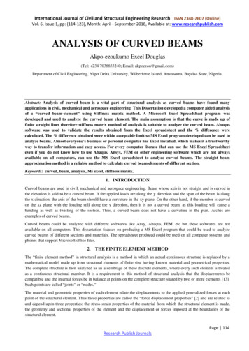
International Journal of Civil and Structural Engineering Research ISSN 2348-7607 (Online)Vol. 6, Issue 1, pp: (114-123), Month: April - September 2018, Available at: www.researchpublish.comANALYSIS OF CURVED BEAMSAkpo-ezoukumo Excel Douglas(Tel: 234 7038855240; Email: akpoezou@gmail.com)Department of Civil Engineering, Niger Delta University, Wilberforce Island, Amassoma, Bayelsa State, Nigeria.Abstract: Analysis of curved beam is a vital part of structural analysis as curved beams have found manyapplications in civil, mechanical and aerospace engineering. This Dissertation developed a computer aided analysisof a “curved beam-element” using Stiffness matrix method. A Microsoft Excel Spreadsheet program wasdeveloped and used to analyze the curved beam element. The main assumption is that the curve is made up offinite straight lines therefore stiffness matrix method of analysis is suitable to analyze the curved beam. Abaqussoftware was used to validate the results obtained from the Excel spreadsheet and the % difference werecalculated. The % difference obtained were within acceptable limit so MS Excel program developed can be used toanalyze beams. Almost everyone’s business or personal computer has Excel installed, which makes it a trustworthyway to transfer information and easy access. For every computer literate that can use the MS Excel Spreadsheeteven if you do not know how to use Abaqus, Ansys, FEM or other engineering software which are not alwaysavailable on all computers, can use the MS Excel spreadsheet to analyze curved beams. The straight beamapproximation method is a reliable method to calculate curved beam elements of different section.Keywords: curved, beam, analysis, Ms excel, stiffness matrix.1. INTRODUCTIONCurved beams are used in civil, mechanical and aerospace engineering. Beam whose axis is not straight and is curved inthe elevation is said to be a curved beam. If the applied loads are along the y direction and the span of the beam is alongthe x direction, the axis of the beam should have a curvature in the xy plane. On the other hand, if the member is curvedon the xz plane with the loading still along the y direction, then it is not a curved beam, as this loading will cause abending as well as twisting of the section. Thus, a curved beam does not have a curvature in the plan. Arches areexamples of curved beams.Curved beams could be analyzed with different softwares like Ansy, Abaqus, FEM, etc but these softwares are notavailable on all computers. This dissertation focuses on producing a MS Excel program that could be used to analyzecurved beams of different sections and materials. The spreadsheet produced could be used on all computer systems andphones that support Microsoft office files.2. THE FINITE ELEMENT METHODThe “finite element method” in structural analysis is a method in which an actual continuous structure is replaced by amathematical model made up from structural elements of finite size having known material and geometrical properties.The complete structure is then analyzed as an assemblage of these discrete elements, where every such element is treatedas a continuous structural member. It is a requirement in this method of structural analysis that the displacements becompatible and the internal forces be in balance at points on the complete structure shared by two or more elements [13].Such points are called “joints” or “nodes.”The material and geometric properties of each element relate the displacements to the applied generalized forces at eachpoint of the structural element. Thus these properties are called the “force displacement properties” [2] and are related toand depend upon three properties: the stress-strain properties of the material from which the structural element is made,the geometry and sectional properties of the element and the displacement or forces imposed at the boundaries of thestructural element.Page 114Research Publish Journals
International Journal of Civil and Structural Engineering Research ISSN 2348-7607 (Online)Vol. 6, Issue 1, pp: (114-123), Month: April - September 2018, Available at: www.researchpublish.comThese force-displacement relationships are usually found either by determining displacements resulting from a known setof forces in equilibrium or determining a set of forces in equilibrium that are required to produce a prescribedconfiguration of the structural element. These two methods of finding the displacement-force or force-displacementrelationships result in two corresponding matrices involving the material and geometric properties of the structuralelement. The former method results in what is called the “flexibility matrix” while the result of the latter method is the“stiffness matrix the two matrices relate forces and displacements in the following manner:{v} [a] (f)(F) [k] {v}Where {v} a generalized displacement vector of n components.{F} a generalized force vector of n components.[a] an nth order square matrix containing the flexibility Coefficients.[k] an nth order square matrix containing the stiffness Coefficients.3. STIFFNESS METHODAs one of the methods of structural analysis, the direct stiffness method, also known as the matrix stiffness method, isparticularly suited for computer-automated analysis of complex structures including the statically indeterminate type. It isa matrix method that makes use of the members' stiffness relations for computing member forces and displacements instructures. The direct stiffness method is the most common implementation of the finite element method (FEM). Inapplying the method, the system must be modeled as a set of simpler, idealized elements interconnected at the nodes. Thematerial stiffness properties of these elements are then, through matrix mathematics, compiled into a single matrixequation which governs the behaviour of the entire idealized structure. The structure’s unknown displacements and forcescan then be determined by solving this equation. The direct stiffness method forms the basis for most commercial and freesource finite element software.The direct stiffness method originated in the field of aerospace. Researchers looked at various approaches for analysis ofcomplex airplane frames. These included elasticity theory, energy principles in structural mechanics, flexibility methodand matrix stiffness method. It was through analysis of these methods that the direct stiffness method emerged as anefficient method ideally suited for computer implementation.4. SIMPLE USE OF THE PRE-WRITTEN PROGRAMThe straight beam approximations (stiffness method) Insert the individual properties of each beam element on the member properties table (Table 3.1: Input table). Insert the nodal force on the Nodes Table (table 3.2 : Input table for external forces on the Nodes) To obtain the displacements on the nodes of the structure, we use the formula: D K-1 * F Where: D Displacement K Global Stiffness Matrix K-1 Inverse of the global stiffness matrix F Applied forces5. EXTRACTED EXAMPLES FROM MY DISSERTATIONQuestion 1: Find the displacements, reactions and final forces of the frame in Fig. Q1 below.Page 115Research Publish Journals
International Journal of Civil and Structural Engineering Research ISSN 2348-7607 (Online)Vol. 6, Issue 1, pp: (114-123), Month: April - September 2018, Available at: www.researchpublish.comTable Q1.1: Properties of all Members in the FrameMEMBER E (KN/m2)3.0E 04(θ)90CD1.0000.0530.0002333.0E 0467.5DE1.0000.0530.0002333.0E 0445EF1.0000.0530.0002333.0E 0422.5FG2.0000.0530.0002333.0E 040GH1.0000.0530.0002333.0E 04337.5HI1.0000.0530.0002333.0E 04315IJ1.0000.0530.0002333.0E 04292.5BJ3.0000.0530.0002333.0E 04270Table Q1.2: Forces on each Node of the frameNODES 050050000000000Page 116Research Publish Journals
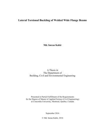
International Journal of Civil and Structural Engineering Research ISSN 2348-7607 (Online)Vol. 6, Issue 1, pp: (114-123), Month: April - September 2018, Available at: www.researchpublish.comUSING ABAQUS TO SOLVE THE PROBLEMFig.Q1.1: Loading and Boundary conditionsFig.Q1.10: SS1 plotFig.Q1.11: Bending Moment Diagram (Full Path)Page 117Research Publish Journals
International Journal of Civil and Structural Engineering Research ISSN 2348-7607 (Online)Vol. 6, Issue 1, pp: (114-123), Month: April - September 2018, Available at: www.researchpublish.comThe results obtained from the MS Excel Spreadsheet and Abaqus for Question 1 are displayed in table Q1.3 , Q1.4 andQ1.5 below.Table Q1.3: Member Displacement �IXΔIYƟIΔIXΔIYƟIΔJXMS 31.08E 044.698171.27E-021.26E 004.648171.27E-02-1.26E 81595.0430.2960.981324.600661.20E 001.0154.4600661.27E 001.0154.594961.89E 00-0.378244.594961.89E 30.485-1.3952.920.502-1.19552.152196% 57.473047.2250112.1513948.573827.912662Page 118Research Publish Journals
International Journal of Civil and Structural Engineering Research ISSN 2348-7607 (Online)Vol. 6, Issue 1, pp: (114-123), Month: April - September 2018, Available at: .042.426387.9126628.8615382.36454Table Q1.4: Reactions on the Nodes of the HXMS .68% 63Page 119Research Publish Journals
International Journal of Civil and Structural Engineering Research ISSN 2348-7607 (Online)Vol. 6, Issue 1, pp: (114-123), Month: April - September 2018, Available at: 6240212.75099Table Q1.5: Final Member Forces of the YMFGPGFXPGFYMGFPGHXPGHYMGHMS % 90555.804364-0.75683.687.028717.26087Page 120Research Publish Journals
International Journal of Civil and Structural Engineering Research ISSN 2348-7607 (Online)Vol. 6, Issue 1, pp: (114-123), Month: April - September 2018, Available at: he percentage difference between the results obtained from the abaqus and the MS Excel calculation sheet is withinacceptable limit. Therefore, this proves that the MS Excel calculation sheet is a good one for calculating curved beams.To further validate the results from the MS Excel program we solved a problem solved as an example in page 412 ofSTRUCTURAL ANALYSIS USING CLASSICAL AND MATRIX METHOD, written by JAMES K. NELSON ANDJACK C. MCCORMAC THIRD EDITION and the results are compared below.Question 5: Find the final forces of the frame in Fig. Q5 below.The results obtained from the MS Excel and that of the textbook are shown below in table Q5.2 together with the %difference.Table Q 5.1: Properties of all Members in the FrameMEMBER PROPERTIESMEMBERL(ft)AC10A(m2)0.053I(m4)0.0002332E (KN/m2)3.0E 04(θ)90CD0.0530.00023323.0E 049010Page 121Research Publish Journals
International Journal of Civil and Structural Engineering Research ISSN 2348-7607 (Online)Vol. 6, Issue 1, pp: (114-123), Month: April - September 2018, Available at: www.researchpublish.comDE100.0530.00023323.0E 0490EF100.0530.00023323.0E 040FG100.0530.00023323.0E 040GH100.0530.00023323.0E 040HI100.0530.00023323.0E 04270IJ100.0530.00023323.0E 04270BJ100.0530.00023323.0E 04270Table Q5.2: Final Member Forces of the YMJBTextbook(kips), 5.56.0717.878.96.0717.8106.2MS Excel(kips), 9% All results obtained are compared and the % difference between the MS excel and the Textbook are within the acceptablerange.Several examples were considered using other softwares like Matlab, Abaqus, Winkler’s method and the MS Excel. Theresults obtained and the percentage differences were calculated and submitted to the department of Civil Engineering inNiger Delta University, Amassoma, Bayelsa State and the results were approved by Dr. Solomon T. Orumu, ProfessorAdewumi K. Ife and the department for my masters degree dissertation.6. CONCLUSIONFrom the results shown in the above example, it can be said that the MS Excel spreadsheet develop using the stiffnessmatrix method yields an approximate result to the Abaqus software results. The developed MS Excel SpreadsheetPage 122Research Publish Journals
International Journal of Civil and Structural Engineering Research ISSN 2348-7607 (Online)Vol. 6, Issue 1, pp: (114-123), Month: April - September 2018, Available at: www.researchpublish.comProgram can be used to analyze curved beams and for every computer literate that can use the Ms Excel Spreadsheet evenif you do not know how to use Abaqus, Ansy, FEM, etc, which are not available on all computers.Based on the results obtained from the example above, the stiffness matrix method of curved beam analysis gives anapproximate result to the exact method. The following recommendations are made:1.The method is an approximate method2.An increase in the number of straight lines would yield more accurate results.3.The longer the length of the curve, more straight lines are required.4.A more familiar software (MS-Excel Spreadsheet) can be used to solve analyze curved beam elements.ACKNOWLEDGEMENTI would like to appreciate the almighty God for his grace upon my life and for helping me achieve my desires in life.I would like to express my appreciation to my Supervisor, Dr. S. T. Orumu, for his guidance, patience and encouragementduring the course of this study. Heartfelt appreciation is also extended to the lecturers of the Department of Civilengineering including the HOD, Dr. Meeting Andaowei for their valuable comments and relentless efforts toward me. Myprofound gratitude also goes to Prof. Adewumi Efeoluwa for his fatherly and academic advice throughout the program.My warm thanks goes to my sweet parents Mr. and Mrs. Apostle J. A. Douglas (the Founder & General overseer, Templeof Holy Hill Church), my precious wife Mrs. Stella K. Douglas, daughter Ebi-emi and Bolouda-owei New-world, myDarling brothers, prophet Don Ebipamene, Moses, Ebimotimi, Ebimieyeseigha, Isaiah, Oyeintarikedou Douglas and mysisters, Timipere, Akpotu, Oyeinmiebi, Perebi, Tariere, Binatari, and Oyeinkepei Douglas for their support financially,morally and otherwise.Finally, I wish to extend my appreciation to all my friends, colleagues and others which I may not mention individually.God bless you all.REFERENCES[1]Argyris, J. 1982: An excursion into large rotations. Computer Methods in Applied Mechanics and Engineering[2]Atluri, S.N.; Cazzani, A. 1995: Rotations in computational solid mechanics. Archives Comput. Methods Engrg.[3]Seely, Fred B., and Smith, James O., Advanced Mechanics of Materials, John Wiley and Sons, New York, 1952.[4]Przemieniecki, J. S. Theory of Matrix Structural Analysis, McGraw-hill, New York, 1968.[5]Azar, Jamal J., Matrix Structural Analysis, Pergamon Press, Inc., Maxwell House, Fairview Park, Elmsford, NewYork, 1972.[6]Cardona, A.; Geradin, M. 1988: A beam finite element non-linear theory with finite rotations. InternationalJournal for Numerical Methods in Engineering 26, 2403-2438[7]Franchi, C.G.; Montelaghi, F. 1996: A weak-weak formulation for large displacements beam statics: a finitevolumes approximation. International Journal for Numerical Methods in Engineering.[8]Ibrahimbegovi c, A. 1995: On finite element implementation of geometrically nonlinear Reissner’s beam theory:three dimensional curved beam elements. Computer Methods in Applied Mechanics and Engineering 122, 11-26[9]Ibrahimbegovi c, A.; Frey, F. 1994: Stress resultant geometrically nonlinear shell theory with drilling rotations –Part II. Computational aspects. Computer Methods in Applied Mechanics and Engineering[10] Ibrahimbegovi c, A.; Frey, F.; Koˇzar, I. 1995: Computational aspects of vector-like parametrization of threedimensional finite rotations. International Journal for Numerical Methods in Engineering 38, 3653-3673[11] Iura, M.; Atluri, S.N. 1988: Dynamic analysis of finitely stretched and rotated threedimensional space-curvedbeams. Computers & Structures 29, 875-889[12] Iura, M.; Atluri, S.N. 1989: On a consistent theory, and variational formulation of finitely stretched and rotated 3D space-curved beams. Computational Mechanics 4, 73-88[13] Jeleni c, G.; Saje, M. 1995: A kinematically exact space finite strain beam model – finite element formulation bygeneralized virtual work principle, Computer Methods in Applied Mechanics and Engineering 120, 131-16Page 123Research Publish Journals
Abstract: Analysis of curved beam is a vital part of structural analysis as curved beams have found many applications in civil, mechanical and aerospace engineering. This Dissertation developed a computer aided analysis of a "curved beam-element" using Stiffness matrix method. A Microsoft Excel Spreadsheet program was