Transcription
FEDERAL ENERGY MANAGEMENT PROGRAMBest Practices Guidefor Energy-EfficientData Center DesignRevised March 2011Prepared by the National Renewable Energy Laboratory (NREL), a national laboratoryof the U.S. Department of Energy, Office of Energy Efficiency and Renewable Energy;NREL is operated by the Alliance for Sustainable Energy, LLC.
Acknowledgements ContactsAcknowledgementsThis report was prepared by John Bruschi, Peter Rumsey, Robin Anliker, Larry Chu, and Stuart Gregson ofRumsey Engineers under contract to the National Renewable Energy Laboratory. The work was supported bythe Federal Energy Management Program led by Will Lintner.ContactsWilliam LintnerU.S. Department of Energy FEMPwilliam.lintner.ee.doe.gov202-586-3120Bill TschudiLawrence Berkeley National Laboratorywftschudi@lbl.gov510-495-2417Otto VanGeetNational Renewable Energy LaboratoryOtto.VanGeet@nrel.gov303-384-7369Errata SheetNREL REPORT/PROJECT NUMBER: NREL/BR-7A40-47201DOE NUMBER: DOE/GO-102010-2956TITLE: FEMP Best Practices Guide for Energy-Efficient Data Center DesignAUTHOR(S): Otto VanGeetORIGINAL PUBLICATION DATE: February 2010DATE OF CORRECTIONS: March 4, 2011The following corrections were made to this report/document:Revised March 2011: Page 4, Figure 2: the green line in the chart has a missing vertical side on the left Action: Need to connect the line (as annotatedin accompanying PDF). Page 16 -17: Need to add Note after last paragraph on page 16: “The Green Grid has proposed and defined a metric forMeasuring the Benefit of Reuse Energy from a Data Center; the Energy Reuse Effectiveness, or ERE. For more information hite-papers/ERE.” Pages 18: Need to add new section after first paragraph on pg 18:(Bold heading) Energy Reuse Effectiveness (ERE)(body) ERE is defined as the ratio of the total energy to run the data center facility minus the reuse energy to the total energydrawn by all IT equipment:ERE Cooling Power Lighting IT-Reuse IT IT Equipment EnergyITFurther examination of the properties of PUE and ERE brings out another important result. The range of val ues for PUE ismathematically bounded from 1.0 to infinity. A PUE of 1.0 means 100% of the power brought to the data center goes to ITequipment and none to cooling, lighting, or other non-IT loads. For ERE, the range is 0 to infinity. ERE does allow values lessthan 1.0. An ERE of 0 means that 100% of the energy brought into the data center is reused elsewhere, outside of the data centercontrol volume. For more information see e-papers/ERE.Instructions for Hard Copies: No revised copies will be printed.On the CoverCenter for Disease Control and Prevention's Arlen Specter Headquarters and Operations Center reached LEED Silver rating through sustainable design and operations that decrease energy consumption by 20% and waterconsumption by 36% beyond standard codes. PIX 16419.Employees of the Alliance for Sustainable Energy, LLC, under Contract No. DE-AC36-08GO28308 with the U.S. Dept. of Energy have authoredthis work. The United States Government retains and the publisher, by accepting the article for publication, acknowledges that the UnitedStates Government retains a non-exclusive, paid-up, irrevocable, worldwide license to publish or reproduce the published form of this work,or allow others to do so, for United States Government purposes.FEDERAL ENERGY MANAGEMENT PROGRAM
Table of ContentsTable of ContentsSummary 1Background 1Information Technology (IT) Systems 1Efficient Servers 1Storage Devices 2Network Equipment 2Power Supplies 2Consolidation 3Hardware Location 3Virtualization 3Environmental Conditions 42009 ASHRAE Guidelines and IT-Reliability 4Air Management 5Implement Cable Management 5Aisle Separation and Containment 5Optimize Supply and Return Air Configuration 7Raising Temperature Set Points 8Cooling Systems 8Direct Expansion (DX) Systems 8Air Handlers 9Central vs. Modular Systems 9Low Pressure Drop Air Delivery 10High-Efficiency Chilled Water Systems 10Efficient Equipment 10Optimize Plant Design and Operation 10Efficient Pumping 11Free Cooling 11Air-Side Economizer 11Water-Side Economizer 12Thermal Storage 12Direct Liquid Cooling 12Humidification 12Controls 12FEDERAL ENERGY MANAGEMENT PROGRAMi
Table of ContentsElectrical Systems 13Power Distribution 13Uninterruptible Power Supplies (UPS) 13Power Distribution Units (PDU) 14Distribution Voltage Options 15Demand Response 15DC Power 15Lighting 16Other Opportunities for Energy-Efficient Design 16On-Site Generation 16Co-generation Plants 16Reduce Standby Losses 16Use of Waste Heat 16Data Center Metrics and Benchmarking 17Power Usage Effectiveness (PUE) and Data Center Infrastructure Efficiency (DCiE) 17Energy Reuse Effectiveness (ERE) 18Rack Cooling Index (RCI) and Return Temperature Index (RTI) 18Heating, Ventilation and Air-Conditioning (HVAC) System Effectiveness 19Airflow Efficiency 19Cooling System Efficiency 20On-Site Monitoring and Continuous Performance Measurement 20Bibliography and Resources 21FiguresFigure 1: Efficiencies at varying load levels for typical power supplies . . . . . . . . . . . . . . . . . . . . . . . . . . . . . . 3Figure 2: 2009 ASHRAE environmental envelope for IT equipment air intake conditions . . . . . . . . . . . . . . . 4Figure 3: Example of a hot aisle/cold aisle configuration . . . . . . . . . . . . . . . . . . . . . . . . . . . . . . . . . . . . . . . . . 6Figure 4: Sealed hot aisle/cold aisle configuration . . . . . . . . . . . . . . . . . . . . . . . . . . . . . . . . . . . . . . . . . . . . . . 7Figure 5: Comparison of distributed air delivery to central air delivery . . . . . . . . . . . . . . . . . . . . . . . . . . . . . . 9Figure 6: Typical UPS efficiency curve for 100 kVA capacity and greater . . . . . . . . . . . . . . . . . . . . . . . . . . . 14TableTable 1: ASHRAE Recommended and Allowable Inlet Air Conditions . . . . . . . . . . . . . . . . . . . . . . . . . . . . . . 4for Class 1 and 2 Data CentersiiFEDERAL ENERGY MANAGEMENT PROGRAM
Summary Background Information Technologies (IT) SystemsSummaryThis guide provides an overview of best practices for energy-efficient data center design which spans thecategories of Information Technology (IT) systems and their environmental conditions, data center air management, cooling and electrical systems, on-site generation, and heat recovery. IT system energy efficiency andenvironmental conditions are presented first because measures taken in these areas have a cascading effect ofsecondary energy savings for the mechanical and electrical systems. This guide concludes with a section onmetrics and benchmarking values by which a data center and its systems energy efficiency can be evaluated. Nodesign guide can offer ‘the most energy-efficient’ data center design but the guidelines that follow offer suggestions that provide efficiency benefits for a wide variety of data center scenarios.BackgroundData center spaces can consume up to 100 to 200 times as much electricity as standard office spaces. With suchlarge power consumption, they are prime targets for energy-efficient design measures that can save money andreduce electricity use. However, the critical nature of data center loads elevates many design criteria—chieflyreliability and high power density capacity—far above energy efficiency. Short design cycles often leave littletime to fully assess efficient design opportunities or consider first cost versus life-cycle-cost issues. This canlead to designs that are simply scaled up versions of standard office space approaches or that reuse strategiesand specifications that worked “good enough” in the past without regard for energy performance. This BestPractices Guide has been created to provide viable alternatives to inefficient data center building practices.Information Technology (IT) SystemsIn a typical data center with a highly efficient cooling system, IT equipment loads can account for over half ofthe entire facility’s energy use. Use of efficient IT equipment will significantly reduce these loads within thedata center, which consequently will downsize the equipment needed to cool them. Purchasing servers equippedwith energy-efficient processors, fans, and power supplies, high-efficient network equipment, consolidatingstorage devices, consolidating power supplies, and implementing virtualization are the most advantageous waysto reduce IT equipment loads within a data center.Efficient ServersRack servers tend to be the main perpetrators of wasting energy and represent the largest portion of the ITenergy load in a typical data center. Servers take up most of the space and drive the entire operation. Themajority of servers run at or below 20% utilization most of the time, yet still draw full power during theprocess. Recently vast improvements in the internal cooling systems and processor devices of servers have beenmade to minimize this wasted energy.When purchasing new servers it is recommended to look for products that include variable speed fans asopposed to a standard constant speed fan for the internal cooling component. With variable speed fans it ispossible to deliver sufficient cooling while running slower, thus consuming less energy. The Energy Starprogram aids consumers by recognizing high-efficiency servers. Servers that meet Energy Star efficiencyrequirements will, on average, be 30% more efficient than standard servers.Additionally, a throttle-down drive is a device that reduces energy consumption on idle processors, so that whena server is running at its typical 20% utilization it is not drawing full power. This is also sometimes referredto as “power management.” Many IT departments fear that throttling down servers or putting idle servers tosleep will negatively impact server reliability; however, hardware itself is designed to handle tens of thousandsof on-off cycles. Server power draw can also be modulated by installing “power cycler” software in servers.During low demand, the software can direct individual devices on the rack to power down. Potential powermanagement risks include slower performance and possibly system failure; which should be weighed againstthe potential energy savings.FEDERAL ENERGY MANAGEMENT PROGRAM1
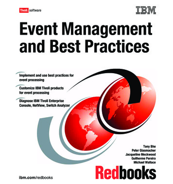
SummaryInformation BackgroundTechnologies (IT)InformationSystems Technologies (IT) SystemsMulti-core processor chips allow simultaneous processing of multiple tasks, which leads to higher efficiencyin two ways. First, they offer improved performance within the same power and cooling load as compared tosingle-core processors. Second, they consolidate shared devices over a single processor core. Not all applications are capable of taking advantage of multi-core processors. Graphics-intensive programs and high performance computing still require the higher clock-speed single-core designs.Further energy savings can be achieved by consolidating IT system redundancies. Consider one power supplyper server rack instead of providing power supplies for each server. For a given redundancy level, integratedrack mounted power supplies will operate at a higher load factor (potentially 70%) compared to individualserver power supplies (20% to 25%). This increase in power supply load factor vastly improves the powersupply efficiency (see Figure 1) in following section on power supplies). Sharing other IT resources such asCentral Processing Units (CPU), disk drives, and memory optimizes electrical usage as well. Short term loadshifting combined with throttling resources up and down as demand dictates is another strategy for improvinglong term hardware energy efficiency.Storage DevicesPower consumption is roughly linear to the number of storage modules used. Storage redundancy needs to berationalized and right-sized to avoid rapid scale up in size and power consumption.Consolidating storage drives into a Network Attached Storage or Storage Area Network are two options thattake the data that does not need to be readily accessed and transports it offline. Taking superfluous data offlinereduces the amount of data in the production environment, as well as all the copies. Consequently, less storageand CPU requirements on the servers are needed, which directly corresponds to lower cooling and power needsin the data center.For data that cannot be taken offline, it is recommended to upgrade from traditional storage methods to thinprovisioning. In traditional storage systems an application is allotted a fixed amount of anticipated storagecapacity, which often results in poor utilization rates and wasted energy. Thin provisioning technology, incontrast, is a method of maximizing storage capacity utilization by drawing from a common pool of purchasedshared storage on an as-need basis, under the assumption that not all users of the storage pool will need theentire space simultaneously. This also allows for extra physical capacity to be installed at a later date as the dataapproaches the capacity threshold.Network EquipmentAs newer generations of network equipment pack more throughput per unit of power, there are active energymanagement measures that can also be applied to reduce energy usage as network demand varies. Suchmeasures include idle state logic, gate count optimization, memory access algorithms and Input/Output bufferreduction.As peak data transmission rates continue to increase, requiring dramatically more power, increasing energy isrequired to transmit small amounts of data over time. Ethernet network energy efficiency can be substantiallyimproved by quickly switching the speed of the network links to the amount of data that is currently transmitted.Power SuppliesMost data center equipment uses internal or rack mounted alternating current/direct current (AC-DC) powersupplies. Historically, a typical rack server's power supply converted AC power to DC power at efficienciesof around 60% to 70%. Today, through the use of higher-quality components and advanced engineering, it ispossible to find power supplies with efficiencies up to 95%. Using higher efficiency power supplies will directlylower a data center’s power bills and indirectly reduce cooling system cost and rack overheating issues. At 0.12/kWh, savings of 2,000 to 6,000 per year per rack (10 kW to 25 kW, respectively) are possible just fromimproving the power supply efficiency from 75% to 85%. These savings estimates include estimated secondarysavings due to lower uninterruptible power supply (UPS) and cooling system loads.2FEDERAL ENERGY MANAGEMENT PROGRAM
Summary Background Information Technologies (IT) SystemsThe impact of real operating loads should also be considered to select power supplies that offer the bestefficiency at the load level at which they are expected to most frequently operate. The optimal power supply loadlevel is typically in the mid-range of its performance curve: around 40% to 60%, as shown in Figure 1.Power Supply Efficiencies100%95%Efficiency90%85%80%48Vdc-12Vdc 350W PSU277Vac-12Vdc 1000W PSU208Vac-12Vdc 1000W PSU240Vac-12Vdc 1000W PSU380Vdc-12Vdc 1200W PSULegacy AC re 1. Efficiencies at varying load levels for typical power supplies(Source: Quantitative Efficiency Analysis of Power Distribution Configurations for Data Centers, The Green Grid)Efficient power supplies usually have a minimal incremental cost at the server level. Power supplies that meetthe recommended efficiency guidelines of the Server System Infrastructure (SSI) Initiative should be selected.There are also several certification programs currently in place that have standardized the efficiencies of powersupplies in order for vendors to market their product. For example, the 80 PLUS program offers certifications forpower supplies with efficiencies of 80% or greater at 20%, 50%, and 100% of their rated loads with true powerfactors of 0.9 or greater.ConsolidationHardware LocationLower data center supply fan power and more efficient cooling system performance can be achieved whenequipment with similar heat load densities and temperature requirements are grouped together. Isolating equipment by environmental requirements of temperature and humidity allow cooling systems to be controlled to theleast energy-intensive set points for each location.This concept can be expanded to data facilities in general. Consolidating underutilized data center spaces to acentralized location can ease the utilization of data center efficiency measures by condensing the implementationto one location, rather than several.VirtualizationVirtualization is a method of running multiple independent virtual operating systems on a single physicalcomputer. It is a way of allowing the same amount of processing to occur on fewer servers by increasing serverutilization. Instead of operating many servers at low CPU utilization, virtualization combines the processingpower onto fewer servers that operate at higher utilization. Virtualization will drastically reduce the numberof servers in a data center, reducing required server power and consequently the size of the necessary coolingequipment. Some overhead is required to implement virtualization, but this is minimal compared to the savingsthat can be achieved.FEDERAL ENERGY MANAGEMENT PROGRAM3
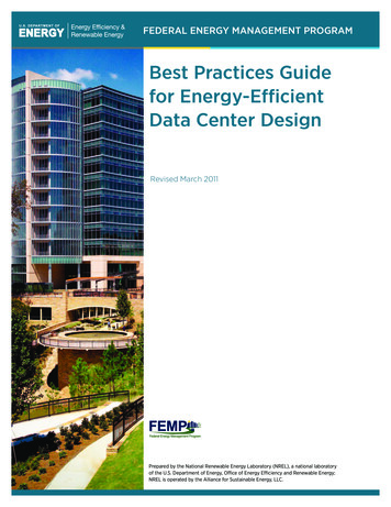
Summary BackgroundEnvironmentalConditions Information Technologies (IT) SystemsEnvironmental Conditions2009 ASHRAE Guidelines and IT-ReliabilityRH 80%The first step in designing the cooling and air management systems in a data center is to look at the standardized operating environments for equipment set forth by the American Society of Heating, Refrigerating andAir-Conditioning Engineers (ASHRAE) or Network Equipment Building System (NEBS). In 2008, ASHRAEin collaboration with IT equipment manufacturers expanded their recommended environmental envelope forinlet air entering IT equipment. The revision of this envelope allows greater flexibility in facility operations, andcontributes to reducing the overall energy consumption. The expanded recommended and allowable envelopesfor Class 1 and 2 data centers are shown in Figure 2 and tabulated in Table 1 (for more details on data centertype, different levels of altitude, etc., refer to the referenced ASHRAE publication, Thermal Guidelines forData Processing Environments, 2nd Edition).0.0160% 5RH0.014Humidity Ratio (lbs H2O per lbs dry air)h 30 Btu/lb0.0120.0100.00820%RH 0.0060.0040.0020.0004550556065707580859095100Dry Bulb Temperature (F)ASHRAE Class 1 and Class 2 Computing Environment, RecommendedASHRAE Class 1 Computing Environment, AllowableASHRAE Class 2 Computing Environment, AllowableFigure 2. 2009 ASHRAE environmental envelope for IT equipment air intake conditions (Source: Rumsey Engineers)Table 1. ASHRAE Recommended and Allowable Inlet Air Conditions for Class 1 and 2 Data Centers (Source: Rumsey Engineers)4Class 1 and Class 2Recommended RangeClass 1 AllowableRangeClass 2 AllowableRangeLow Temperature Limit64.4 F DB59 F DB50 F DBHigh Temperature Limit80.6 F DB89.6 F DB95 F DBLow Moisture Limit41.9 F DP20% RH20% RHHigh Moisture Limit60% RH & 59 F DP80% RH & 62.6 F DP80% RH & 69.8 F DPFEDERAL ENERGY MANAGEMENT PROGRAM
Summary Background Information TechnologiesAir Management(IT) SystemsIt is important to recognize the difference between the recommended and allowable envelopes presented in theASHRAE guidelines. The recommended environmental envelope is intended to guide operators of data centers onthe energy-efficient operation of data centers while maintaining high reliability. The allowable envelope outlinesthe environmental boundaries tested by equipment manufacturers for equipment functionality, not reliability.Another important factor to consider regarding the optimal server inlet air temperature is that variable speedfans in the servers are usually controlled to the internal server temperature. Operating the data center at serverinlet air conditions above the recommended range may cause these internal fans to operate at higher speeds andconsume more power. For example, a data sheet for a Dell PowerEdge blade server indicates a 30% increase inserver fan speed with an increase in inlet air temperature from 77 F to 91 F. This increase in inlet air temperature results in more than doubling the server fan power by applying the fan affinity law where fan powerincreases with the cube of fan speed. Thus, the effect of increasing server inlet air temperature on server fanpower should be carefully weighed against the potential data center cooling system energy savings.Air ManagementAir management for data centers entails all the design and configuration details that go into minimizing oreliminating mixing between the cooling air supplied to equipment and the hot air rejected from the equipment.Effective air management implementation minimizes the bypass of cooling air around rack intakes and therecirculation of heat exhaust back into rack intakes. When designed correctly, an air management system canreduce operating costs, reduce first cost equipment investment, increase the data center’s power density (Watts/square foot), and reduce heat related processing interruptions or failures. A few key design issues include theconfiguration of equipment’s air intake and heat exhaust ports, the location of supply and returns, the large scaleairflow patterns in the room, and the temperature set points of the airflow.Implement C
design guide can offer ‘the most energy-efficient’ data center design but the guidelines that follow offer sugges-tions that provide efficiency benefits for a wide variety of data center scenarios. Background Data center spaces can consume up to 100 to 200 times as much electricity as standard office spaces. With suchFile Size: 899KB