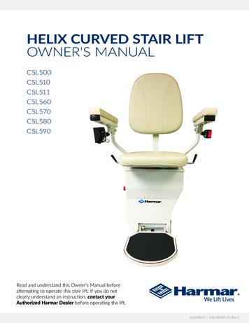
Transcription
Owner’s ManualLiftMat Model#Serial#Placed in serviceSouthworth Products CorporationP.O. Box 1380/Portland, Maine 04104-1380Phone 800-743-1000 FAX hworthproducts.comRevised October 2012
LiftMatDO NOTEVER ATTEMPTTO RAISE PLATFORM ORSCISSOR LIFT OPENMECHANICALLY(CRANE, HOIST, FORK TRUCK, ETC.)THIS WILL IMMEDIATELY DAMAGETHE CYLINDER ANDWAGON ASSEMBLY.THE LIFT MUST BESCISSORED OPEN USING THEHYDRAULIC POWER UNIT.2
Owner’s ManualSOUTHWORTHTABLE OF CONTENTSINTRODUCTION. 4RESPONSIBILITY OF OWNERS AND USERS. 5SAFETY . 6SAFETY SERVICING. 6INSTALLATION INSTRUCTIONS . 7Preparation. 7Positioning the Lift. 7Hydraulic Connections. 7Electrical Connections. 7Testing. 8Completing Installation. 8OPERATING INSTRUCTIONS. 9Safety Label Compliance. 9Labels and Precautionary Markings. 10Operating Procedure.11MAINTENANCE. 12Hazards. 12Routine Periodic Maintenance. 12Repacking the Cylinder. 13Troubleshooting Check List. 14ORDERING REPLACEMENT PARTS. 24Fig 1Fig 2Fig 3Fig 4Fig 5Fig 6Fig 7Fig 8Fig 9Fig 10Fig 11Fig 12Fig 13Fig 14LIST OF FIGURESSafe Servicing of the Lift. 6Center the Load. 8Secure the Load. 8Labels and Precautionary Markings. 10Pinch Points.11Wiring Diagram, Single Phase. 16Three Phase Control Panel. 17Wiring Diagram, Three Phase. 18Hydraulic Schematic. 19Toe Guard Microswitch. 19LiftMat Assembly. 20Wagon Assembly. 21Cylinder Assembly. 22Motor Assembly. 233
LiftMatINTRODUCTIONThe low profile LIFTMAT eliminates the need for installing costly pits. The Lift Mat’s collapsedlow height is low enough that all types of pallet jacks can be rolled onto it with the use of asmall ramp.This manual contains information to acquaint you with the safe and proper use and upkeep ofthe LIFTMAT. You should ensure that this manual is available to personnel working with theLIFTMAT and require its use by these personnel.In the interest of safety please read the entire manual carefully and be familiar with itscontents before you install, use or service the LIFTMAT. If you have any questions about anyinstructions in this manual, please contact your dealer or Southworth Products Corporation.The LIFTMAT is fitted with an identification plate, located on the central cross memberbetween the scissors legs (see fig. 5) The identification plate is stamped with the modelnumber, capacity and serial number. This information should be provided when seeking sparepart inquiries or technical support.Southworth’s product warranty is shown on the back cover of this manual.4
Owner’s ManualSOUTHWORTHResponsibility of Owners and UsersInspection and MaintenanceThe device shall be inspected and maintained in proper working order in accordance withSouthworth’s owner’s manual.Removal from ServiceAny device not in safe operating condition such as, but not limited to, excessive leakage,missing rollers, pins, or fasteners, any bent or cracked structural members, cut or frayedelectric, hydraulic, or pneumatic lines, damaged or malfunctioning controls or safety devices, etc. shall be removed from service until it is repaired to the original manufacturer’sstandards.DeflectionIt is the responsibility of the user/purchaser to advise the manufacturer where deflectionmay be critical to the application.RepairsAll repairs shall be made by qualified personnel in conformance with Southworth’s instructions.OperatorsOnly trained personnel and authorized personnel shall be permitted to operate the lift.Before OperationBefore using the device, the operator shall have: Read and/or had explained, and understood, the manufacturer’s operating instructions and safety rules. Inspected the device for proper operation and condition. Any suspect item shall becarefully examined and a determination made by a qualified person as to whetherit constitutes a hazard. All items not in conformance with Southworth’s specificationshall be corrected before further use of the equipment.During OperationThe device shall only be used in accordance with this owner’s manual. Do not overload. Ensure that all safety devices are operational and in place.Modifications or AlterationsModifications or alterations to any Southworth industrial positioning equipment shall bemade only with written permission from Southworth.5
LiftMatSAFETYThe safety of all persons installing, operating, maintaining, repairing, or in the vicinity of the LIFTMAT is of paramount concernto Southworth. The LIFTMAT is a powerful machine with moving parts, and is capable of causing personal injury ifproper precautions are not taken. Therefore, throughout this manual, Southworth has identified certain hazards whichmay occur in the use of the LIFTMAT and provided appropriate instruction or precautions which should be taken to avoid thesehazards. In some cases, Southworth has also pointed out the consequences that may occur if these instructions or precautionsare not followed. Southworth uses the following system of identifying the severity of the hazards associated with its products:Signal Words: The word or words that designate a degree or level of hazard seriousness. The signal words for product safetysigns are DANGER, WARNING and CAUTION.“DANGER”Indicates an imminently hazardous situation which, if not avoided, will result in death orserious injury. This signal word is to be limited to the most extreme situations.“WARNING”Indicates a potentially hazardous situation which, if not avoided, could result in death orserious injury.“CAUTION”Indicates a potentially hazardous situation which, if not avoided, may result in minor injury.It may also be used to alert against unsafe practices.Please read and follow the instructions in this manual, including all safety instructions and precautions, carefullyand completely.SAFE SERVICING OF THE LIFTThis is the only safe way to work under a lift table. In thismanual, we will refer you to this procedure many times. In theinterest of safety, please follow all of these stepswhenever you work under the lift table:Maintenance Devicenot engaged Remove the payload from the table top. Raise the lift table to the full-up position. Do not let thetable stop part way up. Move the maintenance device into position as shownin Fig. 1. Lower the table so the movable legs are restingagainst the maintenance device. This will release the pressurein the hydraulic system. If you do not do this, pressure mayremain in the hydraulic system. If this pressure is releasedsuddenly, you may be hurt, or the lift may be damaged.Once in position, the maintenance device will keep the legsfrom moving and prevent the lift from dropping suddenly. Thefirst part of Fig. 1 shows the maintenance device engaged,locking the rollers and legs in place. The second part of Fig.1 shows the maintenance device not engaged. This allowsthe table to move freely. Complete the work under the lift table, then reverse theprocess to get the lift ready for operation. Repeat the procedure every time you must work underthe lift. Do this even if you will only be under the table for amoment!MaintenanceDevice engagedFigure 1 – Safe Servicing of the Lift6
Owner’s ManualINSTALLATION INSTRUCTIONSPREPARATION1.Read all of these installation instructions carefully. Be sureto read and understand all of the warnings!3.The power unit will be mounted away from the lift; checkthe mounting arrangement for the power unit. The powerunit should be sheltered from the weather. It should bemounted within 30 feet of the lift to minimize the pressuredrop in the hydraulic system. Be sure the hydraulic lineshave been installed properly.CAUTION!It is very important to keep the hydraulicoil free of dirt, dust, metal chips, water,and other contamination. Most of theproblems with hydraulic systems arecaused by contamination in the oil.WARNING!Be sure that the hydraulic line will not bepinched by the lift as it raises or lowers.If you allow the line to be pinched, thelift may not work properly. A hose maybreak, the lift table may drop suddenly,and someone may be hurt.WARNING!Protect the power unit from rain or moisture.If the electrical parts in the power unit get wet,workers may be hurt by electrical shock. Theelectrical parts may fail if they are wet.CAUTION!It is very important to keep the hydraulicoil free from dirt, dust, metal chips, water,and other contamination. Most of theproblems with hydraulic systems arecaused by contamination of the oil.WARNING!The electric motor in the lift can create sparks.Do not install the power unit in an area whereflammable gases may be present.POSITIONING THE LIFT1.2.Remove the shipping material and unskid the lift. Make surethe packing material is removed from the toe guard and toeguard switches located on each end of the unit under theplatform. On the front of this manual, confirm the modelnumber, serial number, and date the lift is placed in service.You can find the model number and serial number on theidentification plate (see fig. 5).Move the lift into position, supporting the base frame ofthe lift. Install the lift using lag bolts to hold the lift in place.Mount the lift on a firm level surface, if necessary, insertshims to level the lift. Make sure to grout under each siderail to prevent the base frame from flexing.WARNING!If the lift is mounted on an unstablesurface, it may tip over when it is in use.You may be hurt, and the lift and loadmay be damaged.HYDRAULIC CONNECTIONS1.Mount the power unit in a desired location.2.Connect the hydraulic line between the power unit and thelift.Hydraulic Oil SpecificationsDEXRON III ATFBefore you start to install the lift, check for local codesand ordinances which may apply. It is your responsibilityto obtain any necessary permits.2.SOUTHWORTHELECTRICAL CONNECTIONSDANGER!The lift may use a power supply of up to460 Volt AC. This voltage can kill you. Donot work with the electrical parts unlessyou are a qualified electrician.1.A lift with a 115 Volt power unit needs to have a designated20 amp outlet and breaker servicing no other electricaldevices.2.On a lift designed for three-phase AC, you must be surethe pump and motor is turning in the right direction. Thelift table should start to move quickly when you press the“up” or “down” button. If the lift table does not move in 2or 3 seconds, do not try to operate the lift! Exchange anytwo of the three-phase leads. If this does not correct theproblem, see the troubleshooting instructions at the endof this manual.CAUTION!If you have a unit designed for threephase AC and you connect the power sothe motor runs backwards, the lift will notoperate, and you may damage the pump.Do not operate the lift for more than 2 or3 seconds if you think the motor mightbe turning backwards.7
LiftMatTESTINGCOMPLETING INSTALLATION1.Check the level of the hydraulic oil. With the lift in thelowered position, the hydraulic fluid in the tank should bewithin 3/4 of an inch from the top; add oil if necessary.1.2.Clear the area around the lift. Remove any loose wires,lumber, or other material which might get in the way of thelift as it raises or lowers.Once you are sure the lift and ramp are positioned correctly,mark the locations of the lag holes on the floor, and drillthe holes. If necessary, insert metal shims to level the baseof the lift. Insert and tighten the lag bolts to secure the lift.Grout under the base rails to prevent vibration and distortionof the base frame.3.Operate the lift through its full range of travel. The liftshould rise smoothly with a quiet humming sound, andlower smoothly and quietly. Raise and lower the lift a fewtimes to check the clearances around the lift table.2.Test the lift with the rated load. If the lift does not rise andyou hear a loud squealing noise, the pressure relief valveis operating. Contact Southworth for instructions.WARNING!As the lift table moves up and down,“pinch points” are created at the placesshown in Fig. 4. If you are standing toclose to the lift when it is moving, yourarm or leg may be caught in the movingparts, and you may be hurt. Stay awayfrom the pinch points when the lift ismoving.Always place the load inthe center of the lift.Figure 2 – Center the Load8WARNING!If you hear a squealing noise fromthe pump, the pressure relief valve isoperating. Do not continue to use the lift!The pump will over heat very quickly, andmay be permanently damaged. ContactSouthworth for instructions.If the load can roll or move,insert chocks or fasten theload down.Figure 3 – Secure the Load
Owner’s ManualSOUTHWORTHOPERATOR INSTRUCTIONSSAFETY LABEL COMPLIANCETo aid in understanding the concept and the importance of the symbol and signal word, the followinghas been excerpted from ANSI Z535.4.4.10 Safety Alert SymbolsA symbol which indicates a potential personal injury hazard. It is composed of an equilateraltriangle surrounding an exclamation mark. The safety alert symbol shall not be used to alertpersons to property-damage-only accidents.For use with DANGER signal word(Red Background)For use with WARNING signal word(Orange Background)For use with CAUTION signal word(Yellow Background)4.1 Signal WordsThe meaning of different signal words as defined by ANSI Z535.6 and Z535.4 standards may beprovided in collateral materials. The following artwork may be used for this purpose.DANGER indicates a hazardous situation which, if not avoided,will result in death or serious injury.(Red Background)WARNING indicates a hazardous situation which, if not avoided,could result in death or serious injury.(Orange Background)(Yellow Background)CAUTION, used with the safety alert symbol, indicates a hazardous situation which, if not avoided, could result in minor ormoderate injury.NOTICE is used to address practices not related to personalinjury.(Blue Background)9
LiftMatItemPart #Location1 2986178Table skirt(both sides - roller end)2 Capacity Decals500# 29984331000# 29984252000# 29984274000# 2998426Platform ends; two per end, as shown3 2986737Wagon support plate4 2986968Wagon support plate5 5900191Table skirt(both sides - hinged end)7 Control Decals2986999 (115/1/60)2986998 (24/1/60)5900166 (24VDC)ItemPart #Location5900167 (110/1/50)On junction box6 Power Decals2987000 (115/1/60)5900160 (230/1/60)2987001 (208/3/60)2987002 (230/3/60)2987003 (460/3/60)5900162 (575/3/60)2991783 (12VDC)5900161 (24VDC)5900163 (110/1/50)5900164 (220/1/50)2999416 (380/3/50)5900165 (415/3/50)On junction box8 2991782Hydraulic tankFigure 4 – Labels and Precautionary Markings10
Owner’s ManualSOUTHWORTHOPERATING PROCEDURE1.WARNING!As the lift table moves up and down,“pinch points” are created at the placesshown in fig. 4. If you are standing tooclose to the lift when it is moving, yourarm or leg may be caught in the movingparts, and you may be hurt. Stay awayfrom the pinch points when the lift ismoving.Before operating the lift, read and understand this entiresection.DANGER!The lift may use a power supply of up to460 Volts AC. This voltage can kill you. Donot work with the electrical parts unlessyou are a qualified electrician!2.Load the lift correctly. Be sure that the load weighs no more than themaximum rated load for the lift. The maximum ratedload is shown on the platform skirt.WARNING!Do not try to lift a load that exceeds themaximum rating. If you try this, the liftmay fail suddenly. Someone may be hurt,and the lift and load may be damaged. 3.Place the load in the center of the lift table.Do not try to load the lift while the lift table ismoving.If you are lifting pipes or other objects which may beable to roll or move, fasten them down, or chock themin place. (Fig. 2,3)Be sure all workers are clear of the lift. Remove any lumberor other material which may fall onto the lift.4.To operate the lift, press and hold the “up” button to raisethe lift, and the “down” button to lower the lift. If the lift doesnot operate right away, turn off the lift and call a qualifiedmaintenance worker.WARNING!If you hear a squealing noise fromthe pump, the pressure relief valve isoperating. Do not continue to use the lift!The pump will over heat very quickly, andmay be permanently damaged. ContactSouthworth for instructions.WARNING!The warning labels on the lift are therefor safety. If you find that the labels areworn or missing, or have been paintedover, contact Southworth Products forreplacement labels. (shown in fig. 5)WARNING!Do not use the unit to lift people. This unitcan not be equipped for this purpose.Figure 5 – Pinch Points11
LiftMatMAINTENANCEAll servicing should be done by qualified personnel. Qualifiedpersonnel should be able to read and understand wiring andhydraulic diagrams. They should be able to troubleshoot liveelectrical circuits safely and in accordance with acceptedpractice. For safety’s sake, if in doubt, please contact yourdealer or Southworth Products Corporation Customer ServiceDepartment at (800-743-1000).HAZARDS labels are worm or missing, or havebeen painted over, replace them beforereleasing the lift for operation. (Fig 5.)ROUTINE PERIODICMAINTENANCEEVERY MONTH: There are several hazards you should be aware of as youservice the lift:WARNING!DANGER!If you are going to repair the center pivotpins and bushings, you must support thelift table in a special way. Each set of legplates, on both sides of the unit, mustbe clamped together firmly, using largeC-clamps. You can not use the standardmaintenance device with the pivot pinsremoved, they will not support the tabletop. If you do not support the lift tablecorrectly, the top may suddenly dropwhen the pivot pins are removed. Pleasecontact The Southworth CustomerService Dept.The lift may use a power supply of up to460 Volts AC. This voltage can kill you. Donot work with the electrical parts unlessyou are a qualified electrician! 12WARNING!As the lift table moves up and down, “pinchpoints” are created at the places shown inFig. 4. If you are standing too close to thelift when it is moving, your arm or leg maybe caught in the moving parts, and youmay be hurt. Stay away from the pinchpoints when the lift is moving.A falling lift can cause severe personnelinjury. Before working under the lift, raisethe lift and insert the maintenance device.Do this every time you work under the lift.(See page 3)Do not change the setting on the reliefvalve. If you do, this may cause the lift tofail. The lift may suddenly drop. Someonemay be hurt, and the lift and the loadmay be damaged. The hydraulic parts inthe lift are designed to handle a certainamount of pressure. The relief valve isdesigned to relieve this pressure beforeit becomes to great. The relief valve hasbeen included for the protection of all ofthe workers who operate the lift. Release of fluids under high pressurescan cause personal injury. Before youdisconnect any part of the hydraulicsystem, be sure to release the hydraulicpressure. The warning labels on the lift are therefor the safety of the operators. If theVisually inspect the leg rollers, center pivot bushings andpins, cylinder clevis pins and bushing, and the leg hingepins and bushing for signs of wear. Contact Southworthfor instructions for repair of the center pivot pins andbushings. Apply oil or WD-40 to the parts listed in the last step.NOTE: although the bearings are “lifetime lubricated”their performance may be extended by additional periodiclubrication. Check the level and appearance of the hydraulic fluid, withthe lift in the lowered position the hydraulic fluid in the tankshould be within 1/8” from the top. Change the oil if it hasdarkened, or feels gritty or sticky.CAUTION!It is important to use hydraulic fluid withthe correct grade and properties. See thehydraulic specification in this manual.(Fig. 15)EVERY SIX MONTHS OR 500 HOURS OFOPERATION, WHICHEVER COMES FIRST: Raise the lift and insert the maintenancedevice. (See page 3) Check all hydraulic fittings and hoses, and tighten theconnections if necessary. Sometimes the fittings can beworked loose by vibrations from the power unit.
Owner’s ManualSOUTHWORTHWARNING!If a hydraulic fitting becomes loose, orif a hydraulic hose breaks, the hydraulicfluid may escape from the system underpressure. If the lift is raised when thishappens, it can drop quickly. Someonemay be hurt, or the lift or load may bedamaged. The clear plastic vent line and the cylinder rod should befree of hydraulic fluid. If you find much fluid in either place,the cylinder seals may be leaking. (It is also possible thetank may be overfilled.) See the section on “Repacking thecylinder.”Drain and discard the hydraulic fluid. Remove the suctionfilter, inside the tank. Using a high-pressure air hoseblow the filter clean. Reinstall the filter in the tank andreassemble.Refill the tank with new hydraulic fluid to within 3/4 of aninch from the top.CAUTION!If you continue to use the fluid after ithas “worn out,” the moving parts in thesystem will wear more quickly.REPACKING THE CYLINDERThis section will tell you how to repack the Lift Mat Cylinder (seefig. 13). The cylinder packing kit can be purchased through theSouthworth Parts Department at (207) 878-1000 or (800) 7431000. When ordering please specify the model number and theserial number of the lift.2.3.4.5.6.7.8.9.10.11.12.Before beginning this procedure, read and understand thisentire section.WARNING!Before working underneath the lift,always raise the lift and insert themaintenance device. Failure to do so mayresult in damage to the lift and severepersonal injury!1.Before you disassemble the old cylinder, be sure youhave these items on hand:A repacking kit. Parts may be damaged whenyou disassemble the cylinder. You should havereplacement parts on hand so you can reassemblethe lift and use it immediately. A supply of new hydraulic oil. Contaminated oil maydamage the new packing. A container to catch the used oil. WARNING!The warning labels on the lift are therefor safety. If you find that the labels areworn or missing, or have been paintedover, contact Southworth Products forreplacement labels. (Shown in Fig. 5) 13.14.15.16.A clean place to work. Choose a place which will notbe damaged if you spill some oil.Raise the lift and insert the maintenance device. (Seepage 3)Activate the down button to lower the lift onto themaintenance device and to relieve pressure from thecylinder.Disconnect the electrical power at the main disconnect orcircuit breaker, or unplug the machine. This will preventthe lift from moving accidentally while you are workingon it.Disconnect all hydraulic lines and drain them into acontainer.Grind the welds on the upper Clevis pin or remove thekeeper on the Clevis pin that holds the cylinder to thewagon assemble.(Fig. 12)Slide the upper clevis pin out removing the rod end of thecylinder from the wagon assembly (it is not necessary toremove the cylinder from the lift table).Remove the retainer ring to allow the cylinder rod to pullapart from the cylinder barrel. (Fig.13)When repacking the cylinder remove each piece to bereplaced and clean the area thoroughly removing all dirtand fibers.Replacement of the O-rings, Backup rings, wear ring,piston seal, Rod wiper, Rod seal, and inner O-ring isvery important. To replace these the clevis needs to beremoved. When complete replace the clevis to originalposition.(Fig.13)When the replacement of the cylinder seals and O-ringsis complete a general inspection of the cylinder rod andbarrel is required. The rod and barrel should appearsmooth, having no dents, scars or pits cause by rust orany other foreign object. If these conditions are foundcontact your local Southworth Dealer.Lubricate the seals and O-rings with clean grease or oil.Carefully insert the piston and rod back into the cylinder.Be very careful not to pinch or tear any of the new sealsor O-rings as they pass the shoulder inside the cylinder. Itis helpful to tip the rod assembly and twist it as you slideit into the cylinder. Once the piston is inside the cylinder,it should slide easily.With the cylinder reassembled replace the retaining ring,make sure the ring snaps into place solidly.Reconnect the cylinder to the wagon assembly in the lift.Reconnect all hydraulic lines and vent lines. (Fig, 12 13)Replace the hydraulic fluid that was lost with an equalamount of fresh oil.Turn the electrical power on and press the up button. Thepump will self-prime and after a few seconds the cylinder13
LiftMat17.will lift the table off the maintenance device. Remove the maintenance device and cycle the lift up and down a few times to removeany air pockets and to check for leaks.If you have spilled any oil, clean it up!DANGER!Spilled hydraulic oil is very slippery, and may present a fire hazard. Always clean up any spilled oil.TROUBLESHOOTINGPROBLEMLift will not raisePOSSIBLE CAUSEWeight of load too heavyCheck the actual weight of the loadMotor not runningCheck the main disconnect switch, fuses, andwiring to the motor. A 20 amp, designated brakermust be supplied for 110VHydraulic oil level lowWhen lift is raised as far as possible, oil levelshould be 3/4” from bottom of tank. When lift isdown, 3/4” from topLift has reached its upper limitUpper limit switch may need to be adjustedMotor may be “single phasing”If motor hums but does not turn, check motor wiring and line fuses.Motor voltage too lowSupply voltage should be /- 10% of the rating atthe motor terminals.Tank vent pluggedIf supplied, remove solid plug from tank, insertvent plug.Suction filter cloggedClean suction filter as described in periodic maintenanceVacuum leak in suction lineCheck all fittings in suction lineDown valve may be energizedCheck wiring to down valve, and solenoid in thevalveMissing couplingCheck to insure the coupling has been installedbetween the pump and motorDown valve may be leakingRemove down valve and inspect for debris whichmay be preventing it from closing.The lift fails to hold Down valve may be energizedLift will not lowerLift raises tooslowlyLift lowers tooslowlyCHECK THISCheck the solenoid in the valve with a volt meter.Cylinder may be leakingCheck for oil in cylinder in the vent line.Down valve may be de-energizedCheck the solenoid in the valve with a volt meterFlow control needs adjustmentAdjust flow control as neededVoltage may be lowCheck voltage at motor to ensure proper voltageis being suppliedForeign material clogging suction Remove necessary components
3. Operate the lift through its full range of travel. The lift should rise smoothly with a quiet humming sound, and lower smoothly and quietly. Raise and lower the lift a few times to check the clearances around the lift table. WARNING! As the lift table moves up and down, "pinch points" are created at the places shown in Fig. 4.