Transcription
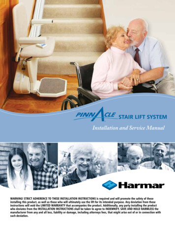
Stair Lift SystemInstallation and Service ManualWARNING! STRICT ADHERENCE TO THESE INSTALLATION INSTRUCTIONS is required and will promote the safety of thoseinstalling this product, as well as those who will ultimately use the lift for its intended purpose. Any deviation from theseinstructions will void the LIMITED WARRANTY that accompanies the product. Additionally, any party installing the productwho deviates from the INSTALLATION INSTRUCTIONS shall be taken to agree to INDEMNIFY, SAVE AND HOLD HARMLESS themanufacturer from any and all loss, liability or damage, including attorneys fees, that might arise out of or in connection withsuch deviation.
Table of ContentsRead and understand this manual prior to attempting stair lift installations. Please refer to the Owner’s Manual forLimited Warranty information and operating instructions. The Owner’s Manual must be given to the owner of thelift before it is put into service.Any alterations to the equipment without written authorization by the manufacturer may void the warranty.Harmar lifts are designed to install with as little assembly by the installer as possible. If you have questions,concerns or comments, please contact Harmar’s Technical Service Department at 1-866-378-6648 ortech@Harmar.com.CONTENTS:I. PRELIMINARY CHECKS .3A. Tools required .3B. Included parts.3II. INSTALLATION PROCEDURES .4A. Determine rail length.4B. Rail installation.5-6C. Chassis installation.7D. Final rail installation.8E. Footrest and seat installation.9-12III. REMOTE CALL/SEND CONTROL OPERATION.12A. Remote control operation.12B. Remote control reprogramming.12IV. COMPLETION PROCEDURES .13A. Test armrest control switch.13B. Tighten brackets.13C. Set upper and lower travel limits.13D. Test safety stop switches.14E. Additional System Checks.15V. Folding Rail Installation.16-20VI. Folding Rail Conversion.20-27Important! It is imperative that this manual be read and understood prior to attempting installation of the stair lift.Please observe all cautions and warnings in this manual, as well as on labels on the equipment.2Pinnacle Stair Lift Manual www.Harmar.com 866-351-2776
Table of ContentsPreliminaryChecksI. PRELIMINARY CHECKSTOOLS REQUIREDThe following is a suggested list of basic tools to have on hand during installation.Cordless drillAllen wrench (5/64”, 5/32”, 3/16”, 5/16”)Phillips screwdriver (#3)Nut driver (3/8” and 5/16”)6-10” driver extensionT30 Torx bit (included)LevelHack saw or chop sawSAE socket setSAE wrenchesTape measureINCLUDED PARTSBefore beginning installation, please inspect and check the box contents. Report any damage to your dealer.Chassis Box: Rail Box: Chassis Bottom rail pre-installed with: Call/send parts Bottom end plate 2 Call/send hand controls Charge strip wire harness Battery charger Bottom limit cam Installation Manual Joint pins and joint brackets Owner’s Manual(two-piece rail only) Plastic gear rack Top rail pre-installed with: Charge strip wire harnessRail Bracket Box: Rail accessories (plastic bag): Rail brackets (2, 3, 4, or 6 per set) Top end plate Wood screws (#14 X 2” (4 per rail bracket) Compression bolts (3 sizes) Self-cutting screws (1/4”-20 X 1”)Chair and Footrest Box: Torx T30 driver bit Chair with seat belt Footrest complete with: Rail parts (plastic bag): Adjustable seat height frame Extra plastic racks (2 or 3) Plastic vertical cover Top limit cam Nylon plugs (5) Seat swivel post with fastenersPinnacle Stair Lift Manual www.Harmar.com 866-351-27763
Table of ContentsInstallationProceduresII. INSTALLATION PROCEDURESA. DETERMINE OVERALL RAIL LENGTH (Only if track did not come pre-cut to length)Step 1: Determine any obstructions that will affect the position and length of the rail. These may include walls,doors, hallway orientation, etc.Step 2: Measure the overall length of the stairs from the nose at the top landing of the stairs to the floor at thebottom (nose to floor measurement, e.g., 128”, see image below).Step 3: For a normal stairway with adequate space for a landing, add 13” to the nose to floor measurement. Thiswill provide enough rail length to allow the stair lift to be adjusted so that the floor-to-seat height will be thesame at both the top and bottom (e.g., 141”).Step 4: If the top landing has restrictions (i.e., a wall or doorway), use the chart below to determine the length ofextension that should be used.Step 5: To cut the rail, use a standard 12” chop saw, with a blade designed to cut aluminum. Do not cut railinside the house (aluminum chips are very hard to remove from carpets).TIP!DO NOT cut the end of the rail that contains the joint holes.Remove the charger strips and wire harness before cutting.Extension7”9”11”13”3.9” 5” 6.1” 7.2”Horizontal intrusion on top landing4Pinnacle Stair Lift Manual www.Harmar.com 866-351-2776
InstallationTable ofProceduresContentsB. RAIL INSTALLATIONStep 1: Open the rail box and remove the contents.Step 2: Position the bottom rail (the rail with end plate attached) directly on the stairswith the end plate towards the bottom of the stairs and the plastic rack facing up. Placean object that measures between 3/4” and 1” between end plate and the floor.TIP!Use the chair box or another heavy object, like a toolbox, at the bottom to prevent therail from sliding down the stairs.Step 3: Position the two ends of the track close together. Locate and connect the plug on the ends of the twocharger harnesses inside the two track pieces.Step 4: With the plastic rack facing up, slide the top rail into the bottom rail and guide them together using thepre-installed pins. Gently tap the top rail if necessary to get them close together. Be cautious not to pinch thecharger harness.Step 5: Install two (2) joint fasteners and firmly tighten with 3/16” Allen wrench. Thenslide rack pieces down to cover joint.Step 6: Turn over joined rails and install the remaining two (2) joint fasteners andfirmly tighten with 3/16” Allen wrench. Then slide rack pieces down to cover joint.Pinnacle Stair Lift Manual www.Harmar.com 866-351-27765
Table of ContentsInstallationProceduresStep 7: Install rail brackets by loosening the screws and snapping each bracket edge into the slot, or slide thebrackets on from the top of the rail.WALLSIDEStep 8:A. For double rails, the first rail bracket should be tightened in placeso when turned over the back of the bracket touches the rear ofthe first step from the bottom landing. The second and third brackets shouldbe placed and tightened on the steps on each side of the rail joint, again sothe back of the bracket touches the rear of the step. The fourth and finalbracket should be placed on the last step before the top landing, againtightening it so it touches the front of the rear of the last step.B. Tighten the first rail bracket in place so when turned over the back of thebracket touches the rear of the first step from the bottom landing. Place theother rail on the last step before the top landing, again tightening it so ittouches the rear of the last step.Step 9: Turn the rail right side up (plastic side facing up).Step 10: Measure any obstruction from the wall (this may include handrails,molding, light switches, etc.) and adjust the edge of the brackets an equal distancefrom the wall.6Pinnacle Stair Lift Manual www.Harmar.com 866-351-2776
InstallationTableProceduresof ContentsStep 11: The underside of the rail must be at least 2” above the stair tread nose to provide clearance for thefootrest. To achieve this 2” clearance move the rail and bracket forward. Once the clearance is 2” tighten allbracket nuts to hold the brackets in position. To maintain the 2” clearance, and to hold the rail in place, secure thebottom bracket to the first step from the floor with 2-2” wood screws, using a 3/8 nut driver on a 6-10” extensionof a cordless drill.C. CHASSIS INSTALLATIONStep 1: Remove plastic bag from chassis box. Lift the chassis with the manual overridehole (on bottom) facing the downhill side of the stairs and gently slide the chassisonto the rail until it makes contact with the plastic rack. DO NOT LET THE CHASSISFREE FALL DOWN THE RAIL.CAUTION! Be careful not to trap fingers between the rail and the chassis.Step 2: Remove the safety tie and turn the red “ON/OFF” switch to the “ON” position (I).Step 3: Use the installation switch (the black switch on the top of the chassis) to movethe chassis at least two (2) feet down the rail, pushing gently on the chassis to ensurethe chassis does not pull any rack to the top.Step 4: Loosen, but do not remove, the four (4) seat-leveling bolts two (2) on eachside of the chassis) and then align them vertically using a level. Firmly tighten the two(2) bolts on the side of the chassis facing the wall.CAUTION! Do not ride on the chassis or lift until the install is complete.Pinnacle Stair Lift Manual www.Harmar.com 866-351-27767
Installation ProceduresD. FINAL RAIL INSTALLATIONStep 1: Install the remaining plastic rack pieces in the upper rail.Step 2: Use a hacksaw or chop saw to cut the last plastic rack piece flush with the railend. Place something on the floor to catch debris or mark and cut the rack outside.The exposed, cut end of the plastic rack should be facing the top end of the rail (thefactory-cut side should butt against the lower rack).Step 3: Slide the top limit cam into one of the cam slots (it doesn’t matter which side),and tighten the pre-inserted Allen screw with a 5/64” Allen wrench. This will be usedto set the final upper limits for the stair lift.Step 4: Remove charging strip from the rail box. Connect charging strip connector to thecharger wire that runs through the center of the rail from the lower charging strips.Insert the two (2) charger strips into the keyed slots at the top of the rail (while standing onthe top landing looking down). The charging strip with the red wire should be inserted intothe left slot with the metal strip facing out. The charging strip with the black wire should beinserted into the right slot with the metal strip pointing out.Bend the red and black wire tabs in toward the center of the rack.Insert excess cable into the rail, leaving the pigtail with the Molex connector.Step 5: Install the end plate to the top of the rack with the four (4) self-cutting Torxscrews using the supplied T30 Torx bit.TIP!8Too much torque applied to these screws may result in damage. Take your time andapply grease to threads.Pinnacle Stair Lifts Manual www.Harmar.com 866-351-2776
Table ofContentsInstallationProceduresStep 6: Install one of the rack pre-compression screws in the threaded hole in the topplate of the rail, and tighten it as firmly as possible by hand with a 5/32” Allen wrench.There are three (3) kinds of pre-compression screws:1.1/2” for tracks under 6’2.3/4” for tracks between 6’ and 12’3.1” for tracks over 12’Step 7: Plug in the battery charger at either end of the rail, depending onthe closest or most convenient location of a wall power supply. Minimizewire length and intrusion.E. FOOTREST & SEAT INSTALLATIONStep 1: Remove footrest from box and use the installation switch to drive thechassis downward to a position about 6” clear of the floor. This will provide asafe area to install and adjust the footrest. Do not drive the unit into bottom stop.Step 2: Turn the red “ON/OFF” switch located on the top of the chassis to the“OFF” position (0).Step 3: Position the footrest onto the two (2) seat-leveling bolts on theoutside of the chassis by aligning the large opening at the slot ends of the footrest.Step 4: Ensure the footrest is fully engaged.Pinnacle Stair Lift Manual www.Harmar.com 866-351-27769
Table of ContentsInstallationProceduresStep 5: Check that the height of the seat base is correctly set for the intended user.A seat height guide is provided behind the plastic footrest shroud. Consult with theclient and use an existing chair or walker with armrests as a guide.If the height of the seat needs to be adjusted, loosen and remove the four (4) boltson the sides of the seat base using a 5/32” Allen wrench. Adjust the seat base up ordown relative to the footrest structure until the holes align, then replace and securelytighten the four (4) bolts.Step 6: Connect the footrest cable to the 6-pin connector on the chassis.Step 7: Position the keyed seat swivel post in the hole in the seat base hole closest tothe top of the stairs. Securely tighten the two (2) bolts on the sides of the hold using a5/32” Allen wrench.Step 8: Use the supplied white plastic plugs to secure the vertical footrest shroud tothe main footrest cover plate.Step 9: Position the seat directly aligned over the carriage and place onto the seatswivel post. Depress the swivel lever until the seat is fully engaged with the swivelpost. Check the swivel lever to test the locking mechanism. THE SYSTEM WILL NOTFUNCTION IF PROPER ENGAGEMENT IS NOT ACHIEVED.Step 10: Connect the seat cable to the 8-pin connector on the chassis.TIP!10When the 6-pin footrest and the 8-pin chair cables are both connected to the chassis, the black installation switch on the chassis is disabled and will not function.Pinnacle Stair Lift Manual www.Harmar.com 866-351-2776
InstallationTable ofProceduresContentsStep 11: The armrest control is factory set for right-handoperation. If the user prefers to operate the armrestcontrols with their left hand, loosen the single screw on theunderside of each armrest and slide each armrest upwards.Disconnect the plug on the armrest control, switch thearmrests, and reconnect the plug. Replace armrests andtighten screws.Step 12: If the lift is equipped with the optional key lock, ensure that the keyswitch on the armrest control is in the locked position (with the key in the verticalposition)Step 13: Turn the red “ON/OFF” switch located on the top of the chassis to the“ON” (I) position. You should hear a single beep and the LED indicator light on thearmrest control should cycle through a test sequence, showing red, yellow and greenrespectively. If any of the system controls or safety sensors are engaged the LEDindicator light will turn to yellow.Step 14: If the LED indicator light is not green, check the safety senors:1.Seat swivel sensor (seat should be in the locked position)2.Footrest lower sensor (check by pushing in on the safety pan on the footrest)3.Upper foot pan safety sensor (check by pushing on the safety pan on the footrest).4.Front foot pan safety sensor (check by pushing on the safety pan on the footrest).5.Uphill safety sensor (ensure nothing is blocking upward passage)6.Downhill safety sensor (ensure nothing is blocking downward passage)If the LED indicator light is still not green after testing sensors, turn the unit off and recheck all wire plugs. Turnthe unit on again and recheck the LED indicator light cycle. When the LED indicator light remains green the lift isready to operate.Pinnacle Stair Lift Manual www.Harmar.com 866-351-277611
Table of Call/SendRemoteContents Control OperationIII. REMOTE CALL/SEND CONTROL OPERATIONA. REMOTE CONTROL OPERATIONThe key switch on the arm of the chair must be in the “ON” position to use theremote call/send control.STEP 1: Press and hold the appropriate directional button on the front of the handcontrol. The LED indicator light will turn green when a signal is being sent.The chair lift will operate with or without a rider. All safety sensors on the chair lift are designed to continue tooperate in their normal mode. The LED light indicator on the armrest will also display the appropriate color.STEP 2: If the chair lift fails to respond, this may indicate the batteries are discharged and need to be replaced.Remove the back cover of the control and replace with commonly available AAA batteries, ensuring that thepolarity is correct.B. REMOTE CONTROL RE-PROGRAMMINGAll call/send controls are factory programmed. Re-programming is not normally necessary during installation.In the event that the remote call/send control needs to be re-programmed, it is essential to program BOTHcontrols in one programming cycle. Do so by completing the following:1.2.3.4.5.6.7.8.9.10.11.12Start with the red “ON/OFF” switch in the “OFF” position (0).Disconnect the 6-pin footrest and 8-pin chair wire harnesses from the chassis.Press and hold the install switch (located on the top of the chassis) in either direction.Turn the red “ON/OFF” switch to the “ON” position (I), and then release the install switch.The lift will begin to beep rapidly (this means the first remote control is ready to program).Press and release the “UP” or “DOWN” button of the first remote control (the first remote control is nowprogrammed).Press and release the “UP” or “DOWN” button of the second remote control (the second remote control is nowprogrammed).Upon completion, two beeps will indicate that both remote controls have been programmed.Turn the “ON/OFF” switch to the “OFF” position (0).Connect the 6-pin footrest and 8-pin chair wire harnesses to the chassis and then turn the red “ON/OFF” switch tothe “ON” position (I).Test each remote control in both the up and down directions.Pinnacle Stair Lift Manual www.Harmar.com 866-351-2776
CompletionTable ofProceduresContentsIV. COMPLETION PROCEDURESA. TEST ARMREST CONTROL SWITCHSTEP 1: Ensure that the unit travels correctly by operating the armrest control switch while standing in front of theunit.STEP 2: Depress the switch in the upstairs direction to move up. The lift will beep, wait three (3) seconds andbegin to smoothly accelerate upwards. The lift will continue to move upwards as long as the switch is depressed.STEP 3: Release the switch and the lift will come to an immediate stop.STEP 4: Depress the switch in the downstairs direction to move down. The lift will beep, wait three (3) secondsand begin to smoothly accelerate downwards.STEP 5: Release the switch and the lift will come to an immediate stop.STEP 6: Run the chair all the way up and down the rail to ensure that the top of the seat back has at least a 1/2”clearance from the wall and any obstructions.CAUTION! Do not ride on the chassis or lift until the install is complete.B. TIGHTEN BRACKETSSTEP 1: Install and fully tighten the rail bracket mounting screws (four (4) screws per bracket). For hardwoodstairs, a pilot hole should be drilled first. For plywood or particle board stairs care must be taken to preventstripping.C. SET UPPER AND LOWER TRAVEL LIMITSSTEP 1: Test the lower travel limit by operating the lift downward, keeping the switch depressed. The unit shouldbegin to decelerate about 3” from its final resting position and stop clear of the floor.STEP 2: The final stopped position can be adjusted to accommodate the height of the user by repositioning thelimit cam located in a slot in the rail.STEP 3: Use a 5/64” Allen wrench to loosen the set screw in the limit cam. Adjust the limit cam up or down andretighten the set screws. Repeat the above steps until the lift stops in the desired position.Pinnacle Stair Lift Manual www.Harmar.com 866-351-277613
Table of ContentsCompletionProceduresSTEP 4: Repeat the above steps to set the upper limits. For safety, the footrest should be set at least level with theupper landing.STEP 5: The optimum position is met when the seat height above the floor is the same at the top and bottom of the stairs.D. TEST SAFETY STOP SWITCHESSTEP 1: Safety stop switches are located in both the upward and downward ends of the chassis providing protectionfrom obstructions on the rail.STEP 2: Safety stop switches are located in the footrest bottom pan providing protection from obstructions andtrapping hazards on the stairs.STEP 3: A safety stop switch is part of the swivel seat mechanism and prevents the lift from operating when theswivel is in use.STEP 4: Test all the safety stop switches by driving the lift down and touching the downward end of the chassis, thelower edge of the footrest, and the underside of the footrest in both its folded and unfolded positions.STEP 5: In each of the above cases the unit should come to an immediate halt. The LED indicator light on the armrestcontrol should turn to orange and the unit should beep intermittently.STEP 6: When the control switch is released, the unit should NOT be able to be driven in the direction that the liftinitially engaged the obstacle. Test this condition.STEP 7: Test to ensure that the lift can only be driven away from the obstruction. The LED indicator light will turn togreen and stop beeping indicating a safe operating condition.STEP 8: Repeat the above tests while driving the lift in opposite direction.STEP 9: If any safety condition does not function properly, carefully review all installation instructions, reset the “ON /OFF” switch and check that the LED indicator light is green. Repeat the above tests.STEP 10: If any safety stop switch fails to immediately stop the lift and/or a red LED indicator light appears, removethe key to prevent further use of the lift and immediately call the manufacturer for assistance in diagnosing andrepairing the problem. DO NOT USE THE LIFT.14Pinnacle Stair Lift Manual www.Harmar.com 866-351-2776
CompletionTable ofProceduresContentsE. ADDITIONAL SYSTEM CHECKSSTEP 1: After the successful testing of all safety switches, sit on the lift and operate to the top of the stairs.Keeping the control switch depressed continuously, the lift should gently decelerate and then stop at the top ofthe track.STEP 2: As a final adjustment, sit on the lift and do two (2) complete up trips and stop with the chair at thebottom. Then tighten the compression screw in the top end plate, then run the chair to the top and again tightenthe compression screw. Run the chair to the middle and do a final tightening of the compression screw.STEP 3: Drive the lift to the bottom, keeping the control switch depressed all the time, and check that the lift gentlydecelerates and stops so the footrest pan is clear of the floor. If necessary adjust the limit cams with a 5/64” Allenwrench.STEP 4: Move the lift about three (3) feet from either the top or bottom of the rail. After 30 seconds the armrestLED indicator light will show orange and beep indicating that the lift is not positioned on a charge point. Thebeep will stop after 30 seconds, but the armrest LED indicator light will continue to flash orange.STEP 5: Test the seat swivel at the top by using the levers and swiveling the seat towards the landing and stopthe seat at 35 and 85 degrees. The seat swivel levers will release into a locked position at each of these angles.The lift will not operate in any of these positions if the control switch is depressed, and the LED indicator light willturn orange. Return the seat to its normal position and the LED indicator light will turn green and the lift will nowoperate normally.STEP 6: Drive to the top or bottom and check the battery charging light. If the light is orange or red, the batteries arebeing charged.THE LIFT IS NOW READY TO FOR USE.Pinnacle Stair Lift Manual www.Harmar.com 866-351-277615
FoldingInstallationTableof RailContentsV. FOLDING RAIL INSTALLATIONNOTE!The photos in this section show a ‘left’ folding rail, assembled to be installed on the leftside of the stairway. If you’re assembling a ‘right’ side, please complete all of thesesteps in mirror-image to what’s shown. The rail can be disassembled and switched froma ‘left’ or a ‘right’ if necessary. Instructions for this procedure can be found on page20 of this book. As always, if you encounter any difficulty, please call Harmar TechnicalSupport toll free at 866-378-6648.A. RAIL INSTALLATION PREPARATIONTOOLS REQUIREDThe following is a suggested list of basic tools to have on hand during installation.WrenchesHigh torque drillAllen wrenches (standard SAE set)Carpenter’s squarePencilTape measureINCLUDED PARTSBefore beginning folding rail installation, please inspect and check the box contents. Please note that the PinnacleParts Box is omitted on new units since these parts are factory installed on the stair lift. Report any damage toHarmar or the freight carrier.Rail Box: Assembled Folding RailTrack Bracket Box: Two (or more) assembled short track brackets, rack pieces, two adjustable feetPinnacle Parts Box: Folding track side-plate Screw Modified front and rear Pinnacle safety switch bumpers. For new units, this box isomitted and these parts are already installed on the stair lift.16Pinnacle Stair Lift Manual www.Harmar.com 866-351-2776
FoldingTableRail ofInstallationContentsB. FOLDING RAIL INSTALLATION PROCEDURESSTEP 1: Orient the two track brackets onto the folding rail asshown at right, with the nuts on the same side as the foldingmechanism (for either left or right folding).STEP 2: Expand and snap the two brackets over the track, so thetop is in the bracket-groove.STEP 3: Tighten partially the two whiz nuts that position these onthe track, using a ½ wrench (deep socket preferred), so they won’tslide when you’re test-fitting the position.STEP 4: Place the track onto the stairway with the bottom bracketon the second step, as shown. Note that the bottom feet shouldapproximately rest on the floor with the rail straight, but they willbe adjusted later. If you’re adding the folding rail to an existingstairway, run the Pinnacle all the way to the top of the stairs so it isout of the way. Note that the track brackets install with the roundhead of the carriage bolts facing the stairs, the nuts are toward thewall. In this position, they are designed to lean the track slightlytoward the wall.STEP 5: Measure to verify that the underside of the rail is morethan 2 inches from the stair noses, both at the second stepbracket and at the upper bracket. If not, reposition the brackets asneeded. This clearance is required for the stair lift footrest. In someinstallations, you may not be able to get 2 or more inches with thestandard stair-bracket. Contact Harmar to get higher brackets.Bottom bracket 2 inchesUpper folding rail 2 inchesSTEP 6: Retrofits: FIT THE RAIL: If this is a new-install, the upper rail will be pre-cutat the factory to the correct length. If this installation is a retrofit to an existingstair lift, use a carpenter’s square to match-mark from the top of the foldingrail to the point on the existing rail where it will have to be cut to splice.Pinnacle Stair Lift Manual www.Harmar.com 866-351-277617
Folding Rail InstallationSTEP 7: Retrofits to existing stair lifts, measure how much you’vemarked to cut from the upper section, but don’t cut it at the splicebecause you’ll need to keep the countersunk holes. Instead, removethe very top cap and cut it from the top of the very top track piece.Loosen the remaining brackets and slide the tracks all up so the newcut part is at the top where the old part was.Measure from bottom, cutfrom the topDon’t cut off these holes!STEP 8: Retrofit to existing track, saw the track following the usual procedure,described in the installation manual.STEP 9: Measure from the side of the rail to the wall. The minimum clearance thatwill work with a folding stair lift rail is 3 inches. Set the folding section of the stair liftrails to a distance of 3 inches from the wall or more. This will leave about 1/2 inch ofclearance at the ball of the gas-spring.STEP 10: Fasten down the near corner of the lower bracket using a drill that hasextensions at least ten-inches long and a 3/8” socket.Measure and set tothree inches.STEP 11: Measure from the side of the rail at the upper bracket of the folding rail.Also set this at 3 inches or more. Screw down one corner of the bracket.STEP 12: Install new or join to existing upper rail, following regular procedures(this procedure is detailed in the Pinnacle Installation Manual (not shown). Thisprocedure includes plugging the battery charging wire harness for the folding railinto the charging harness from the upper track. The charger itself can be plugged intoeither the top rail (for the top of the stairs), or to the charge plug from the folding rail,which comes out just higher than the folding mechanism for the bottom of the stairway.STEP 13: Fasten down the other three bolts of both track brackets using the power drilland long extension with the 3/8” socket.18Pinnacle Stair Lift Manual www.Harmar.com 866-351-2776
Folding Rail InstallationSTEP 14: Install and adjust the height of the two feet using a 9/16 open end wrench.Set them so that both rest on the floor with the rail fully straight. The foot fartherfrom the wall should be set a little taller than the inside one to get it to seat flat on thefloor, since the Pinnacle track brackets intentionally lean the track toward the wall justa little.STEP 15: If you’re installing the feet onto carpet, you may want to screw-down a piece ofwood or metal to make the feet seat reliably. Otherwise,
2 Pinnacle Stair Lift manual www.Harmar.com 866-351-2776 tf Contentstable oable of Contents Read and understand this manual prior to attempting stair lift installations. Please refer to the Owner's Manual for Limited Warranty information and operating instructions. The Owner's Manual must be given to the owner of the