Transcription
User’s ManualForDMA860HFully Digital Stepper DriveVersion 1.0 2012 All Rights ReservedAttention: Please read this manual carefully before using the drive!3/F, Block 2, Nanyou Tianan Industrial Park, Nanshan Dist, Shenzhen, ChinaT: (86)755-26409254Web site: www.leadshine.comF: (86)755-26402718E-Mail: sales@leadshine.com 2012 by Leadshine Technology Company Limited.All Rights Reserved
Leadshine reserves the right to make changes without further notice to any products herein to improve reliability, function or design.Leadshine does not assume any liability arising out of the application or use of any product or circuit described herein; neither does itconvey any license under its patent rights of others.Leadshine’s general policy does not recommend the use of its products in life support or aircraft applications wherein a failure ormalfunction of the product may directly threaten life or injury. According to Leadshine’s terms and conditions of sales, the user ofLeadshine’s products in life support or aircraft applications assumes all risks of such use and indemnifies Leadshine against all damages.
ContentsTable of Contents1. Introduction, Features and Applications. 1Introduction. 1Features. 1Applications. 12. Specifications. 1Electrical Specifications.1Operating Environment and other Specifications.2Mechanical Specifications. 2Elimination of Heat. 23. Pin Assignment and Description.3Connector P1 Configurations.3Selecting Active Pulse Edge or Active Level and Control Signal Mode. 3Connector P2 Configurations.44. Control Signal Connector (P1) Interface. 45. Connecting the Motor. 4Connections to 4-lead Motors.4Connections to 6-lead Motors.5Half Coil Configurations.5Full Coil Configurations. 5Connections to 8-lead Motors.5Series Connections.6Parallel Connections. 66. Power Supply Selection. 6Regulated or Unregulated Power Supply.6Multiple Drivers. 7Selecting Supply Voltage. 77. Selecting Microstep Resolution and Driver Output Current. 7Microstep Resolution Selection. 7Current Settings.8Dynamic Current Setting. 8Standstill Current Setting.82 8 B Auto Tuning by SW4. 88. Wiring Notes. 99. Typical Connection. 910. Sequence Chart of Control Signals. 1011. Protection Functions.1112. Frequently Asked Questions. 11Problem Symptoms and Possible Causes. 11APPENDIX. 12Twelve Month Limited Warranty.12Exclusions. 12Obtaining Warranty Service.12I
DMA860H Fully Digital Stepper Drive Manual V1.0Warranty Limitations. 13Contact Us. 13II
DMA860H Fully Digital Stepper Drive Manual V1.01. Introduction, Features and ApplicationsIntroductionThe DMA860H is a fully digital stepper drive developed with advanced DSP control algorithm based on the latestmotion control technology. It has achieved a unique level of system smoothness, providing optimal torque and nullsmid-range instability. Its motor auto-identification and parameter auto-configuration feature offers quick setup tooptimal modes with different motors. Compared with traditional analog drives, DMA860H can drive a stepper motor atmuch lower noise, lower heating, and smoother movement. Its unique features make DMA860H an ideal choice forhigh requirement applications.Features Anti-Resonance provides optimal torque and nulls mid-range instability Motor auto-identification and parameter auto-configuration technology, offers optimal responses with differentmotors Multi-Stepping allows a low resolution step input to produce a higher microstep output, thus offers smoothermotor movement 16 selectable microstep resolutions including 400, 800, 1600, 3200, 6400, 12800, 25600, 51200, 1000, 2000, 4000,5000, 8000, 10000, 20000, 40000 Soft-start with no “jump” when powered on Input voltage 18-80VAC or 26-113VDC 8 selectable peak current including 2.40A, 3.08A, 3.77A, 4.45A, 5.14A, 5.83A, 6.52A, 7.20A Pulse input frequency up to 200 KHz, TTL compatible and optically isolated input Automatic idle-current reduction Suitable for 2-phase and 4-phase motors Support PUL/DIR and CW/CCW modes Over-voltage, over-current protectionsApplicationsSuitable for a wide range of stepping motors, from NEMA size 23 to 42. It can be used in various kinds of machines,such as X-Y tables, engraving machines, labeling machines, laser cutters, pick-place devices, and so on. Particularlyadapt to the applications desired with low noise, low heating, high speed and high precision.2. SpecificationsElectrical Specifications (Tj 25 /77 )ParametersDMA860HMinTypicalMaxUnit1.0-7.2 (Peak)A184880VAC2668113VDCLogic Signal Current71016mAPulse input frequency0-200kHzPulse Width2.5--uSOutput CurrentInput Voltage1
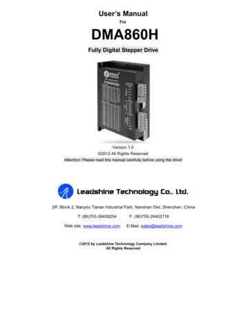
DMA860H Fully Digital Stepper Drive Manual V1.0Pulse Voltage-5Isolation resistance500-VDCMΩOperating Environment and other SpecificationsCoolingNatural Cooling or Forced coolingAvoid dust, oil fog and corrosive gasesEnvironmentOperating EnvironmentAmbient Temperature0 - 50 Humidity40%RH - 90%RHOperating Temperature70 MaxVibration5.9m/s2 MaxStorage Temperature-20 - 65 WeightApprox. 620g (21.9oz)Mechanical SpecificationsFigure 1: Mechanical specifications*Recommend use side mounting for better heat dissipationElimination of Heat Driver’s reliable working temperature should be 70 (158 ), and motor working temperature should be 80 (176 );It is recommended to use automatic idle-current mode, namely current automatically reduce to 50% when motorstops, so as to reduce driver heating and motor heating;It is recommended to mount the driver vertically to maximize heat sink area. Use forced cooling method to cool2
DMA860H Fully Digital Stepper Drive Manual V1.0the system if necessary.3. Pin Assignment and DescriptionThe DMA860H has two connectors, connector P1 for control signals connections, and connector P2 for power andmotor connections. The following tables are brief descriptions of the two connectors. More detailed descriptions of thepins and related issues are presented in section 4, 5, 9.Connector P1 ConfigurationsPin FunctionPulse signal: In single pulse (pulse/direction) mode, this input represents pulse signal, eachrising or falling edge active (set by inside jumper J1); 4.5-5V when PUL-HIGH, 0-0.5V whenPUL-LOW. In CW/CCW mode (set by inside jumper J2), this input represents clockwise (CW)pulse. For reliable response, pulse width should be longer than 2.5μs.PUL PUL-DIR signal: In single-pulse mode, this signal has low/high voltage levels, representing twodirections of motor rotation; in CW/CCW mode (set by inside jumper J2), this signal iscounter-clock (CCW) pulse. For reliable motion response, DIR signal should be ahead of PULsignal by 5μs at least. 4.5-5V when DIR-HIGH, 0-0.5V when DIR-LOW. Please note thatrotation direction is also related to motor-driver wiring match. Exchanging the connection oftwo wires for a coil to the driver will reverse motion direction.DIR DIRENA ENA-DetailsEnable signal: This signal is used for enabling/disabling the driver. High level (NPN controlsignal, PNP and differential control signals are on the contrary, namely low level for enabling.)for enabling the driver and low level for disabling the driver. Usually left UNCONNECTED(ENABLED).Selecting Active Pulse Edge or Active Level and Control Signal ModeThere are two jumpers J1 and J2 inside the DMA860H specifically for selecting active pulse edge and control signalmode, as shown in figure 2. Default setting is PUL/DIR mode and upward-rising edge active. (Note: J3 inside thedriver is used to reverse the default rotation direction.)(a) J1, J2 open circuit(b) J1 open circuit, J3 shirt circuitPUL/DIR mode and Active at rising edge (NPN)PUL/DIR mode and active at falling edge (NPN)(c) J1 short circuit, J3 open circuit(d) J1, J3 short circuitCW/CCW mode and Active at rising edge (NPN)CW/CCW mode and active at falling edge (NPN)Figure 2: J1 and J2 jumper Settings3
DMA860H Fully Digital Stepper Drive Manual V1.0Connector P2 ConfigurationsPin FunctionACACDetailsPower supply, 18 80 VAC or 26-113VDC, Including voltage fluctuation and EMF voltage.A , A-Motor Phase AB , B-Motor Phase B4. Control Signal Connector (P1) InterfaceThe DMA860H can accept differential and single-ended inputs (including open-collector and PNP output). TheDMA860H has 3 optically isolated logic inputs which are located on connector P1 to accept line driver control signals.These inputs are isolated to minimize or eliminate electrical noises coupled onto the drive control signals. Recommenduse line driver control signals to increase noise immunity of the driver in interference environments. In the followingfigures, connections to open-collector and PNP signals are illustrated.DriveControllerVCCControllerPUL PULPULPULPUL VCCDIR DIRDIRDIRDrivePULDIR DIR-ENA ENABLEENA-ENA ENA-ENABLEFigure 3: Connections to open-collectorsignal (common-anode)Figure 4: Connection to PNP signal (common-cathode)5. Connecting the MotorThe DMA860H can drive any 2-pahse and 4-pahse hybrid stepping motors.Connections to 4-lead Motors4 lead motors are the least flexible but easiest to wire. Speed and torque will depend on winding inductance. In settingthe driver output current, multiply the specified phase current by 1.4 to determine the peak output current.4
DMA860H Fully Digital Stepper Drive Manual V1.0Figure 5: 4-lead Motor ConnectionsConnections to 6-lead MotorsLike 8 lead stepping motors, 6 lead motors have two configurations available for high speed or high torque operation.The higher speed configuration, or half coil, is so described because it uses one half of the motor’s inductor windings.The higher torque configuration, or full coil, uses the full windings of the phases.Half Coil ConfigurationsAs previously stated, the half coil configuration uses 50% of the motor phase windings. This gives lower inductance,hence, lower torque output. Like the parallel connection of 8 lead motor, the torque output will be more stable at higherspeeds. This configuration is also referred to as half chopper. In setting the driver output current multiply the specifiedper phase (or unipolar) current rating by 1.4 to determine the peak output current.Figure 6: 6-lead motor half coil (higher speed) connectionsFull Coil ConfigurationsThe full coil configuration on a six lead motor should be used in applications where higher torque at lower speeds isdesired. This configuration is also referred to as full copper. In full coil mode, the motors should be run at only 70% oftheir rated current to prevent over heating.Figure 7: 6-lead motor full coil (higher torque) connectionsConnections to 8-lead Motors8 lead motors offer a high degree of flexibility to the system designer in that they may be connected in series or parallel,thus satisfying a wide range of applications.5
DMA860H Fully Digital Stepper Drive Manual V1.0Series ConnectionsA series motor configuration would typically be used in applications where a higher torque at lower speeds is required.Because this configuration has the most inductance, the performance will start to degrade at higher speeds. In seriesmode, the motors should also be run at only 70% of their rated current to prevent over heating.Figure 8: 8-lead motor series connectionsParallel ConnectionsAn 8 lead motor in a parallel configuration offers a more stable, but lower torque at lower speeds. But because of thelower inductance, there will be higher torque at higher speeds. Multiply the per phase (or unipolar) current rating by1.96, or the bipolar current rating by 1.4, to determine the peak output current.Figure 9: 8-lead motor parallel connections6. Power Supply SelectionThe DMA860H can match medium and small size stepping motors (from NEMA frame size 17 to 34) made byLeadshine or other motor manufactures around the world. To achieve good driving performances, it is important toselect supply voltage and output current properly. Generally speaking, supply voltage determines the high speedperformance of the motor, while output current determines the output torque of the driven motor (particularly at lowerspeed). Higher supply voltage will allow higher motor speed to be achieved, at the price of more noise and heating. Ifthe motion speed requirement is low, it’s better to use lower supply voltage to decrease noise, heating and improvereliability.Regulated or Unregulated Power SupplyBoth regulated and unregulated power supplies can be used to supply the driver. However, unregulated power suppliesare preferred due to their ability to withstand current surge. If regulated power supplies (such as most switchingsupplies.) are indeed used, it is important to have large current output rating to avoid problems like current clamp, forexample using 4A supply for 3A motor-driver operation. On the other hand, if unregulated supply is used, one may usea power supply of lower current rating than that of motor (typically 50% 70% of motor current). The reason is thatthe driver draws current from the power supply capacitor of the unregulated supply only during the ON duration of thePWM cycle, but not during the OFF duration. Therefore, the average current withdrawn from power supply isconsiderably less than motor current. For example, two 3A motors can be well supplied by one power supply of 4Arating.6
DMA860H Fully Digital Stepper Drive Manual V1.0Multiple DriversIt is recommended to have multiple drivers to share one power supply to reduce cost, if the supply has enough capacity.To avoid cross interference, DO NOT daisy-chain the power supply input pins of the drivers. (Instead, please connectthem to power supply separately.)Selecting Supply VoltageThe power MOSFETS inside the DMA860H can actually operate within 24 80VDC, including power inputfluctuation and back EMF voltage generated by motor coils during motor shaft deceleration. Higher supply voltage canincrease motor torque at higher speeds, thus helpful for avoiding losing steps. However, higher voltage may causebigger motor vibration at lower speed, and it may also cause over-voltage protection or even driver damage. Therefore,it is suggested to choose only sufficiently high supply voltage for intended applications, and it is suggested to usepower supplies with theoretical output voltage of 20 68VDC, leaving room for power fluctuation and back-EMF.7. Selecting Microstep Resolution and Driver Output CurrentThis driver uses an 8-bit DIP switch to set microstep resolution, and motor operating current, as shown below:Microstep Resolution SelectionMicrostep resolution is set by SW5, 6, 7, 8 of the DIP switch as shown in the following table:MicrostepSteps/rev.(for 1.8 FFOFFOFF20040000OFFOFFOFFOFF7
DMA860H Fully Digital Stepper Drive Manual V1.0Current SettingsFor a given motor, higher driver current will make the motor to output more torque, but at the same time causes moreheating in the motor and driver. Therefore, output current is generally set to be such that the motor will not overheat forlong time operation.Since parallel and serial connections of motor coils will significantly change resulting inductance and resistance, it istherefore important to set driver output current depending on motor phase current, motor leads and connection methods.Phase current rating supplied by motor manufacturer is important in selecting driver current, however the selection alsodepends on leads and connections.The first three bits (SW1, 2, 3) of the DIP switch are used to set the dynamic current. Select a setting closest to yourmotor’s required current.Dynamic Current SettingREF k ONONOFFOFFOFFOFFNotes: Due to motor inductance, the actual current in the coil may be smaller than the dynamic current setting,particularly under high speed condition.Standstill Current SettingSW4 is used for this purpose. OFF meaning that the standstill current is set to be half of the selected dynamic current,and ON meaning that standstill current is set to be the same as the selected dynamic current.The current automatically reduced to 50% of the selected dynamic current one second after the last pulse. Theoretically,this will reduce motor heating to 36% (due to P I2*R) of the original value. If the application needs a differentstandstill current, please contact Leadshine.2 8BAuto Tuning by SW4To get the optimized performance, switch SW4 two times in one second to identify the motor parameter after power-upif it is the first time installation. The motor parameter is identified and the drive’s current loop parameters arecalculated automatically when SW4 is activated. The motor shaft will have a little vibration during auto-configuration.If the user changes the motor or the power supply, don’t forget to toggle SW4 once again.8
DMA860H Fully Digital Stepper Drive Manual V1.0Auto Tuning Requirement and Procedure:1. Motor is connected to drive.2. Power is connected to drive.3. Turn on the power.4. Make sure there is no pulse applied to drive.5. Switch SW4 two times in one second. That isOFF-ON-OFF or ON-OFF-ON.8. Wiring Notes In order to improve anti-interference performance of the driver, it is recommended to use twisted pair shield cable. To prevent noise incurred in PUL/DIR signal, pulse/direction signal wires and motor wires should not be tied uptogether. It is better to separate them by at least 10 cm, otherwise the disturbing signals generated by motor willeasily disturb pulse direction signals, causing motor position error, system instability and other failures. If a power supply serves several drivers, separately connecting the drivers is recommended instead ofdaisy-chaining. It is prohibited to pull and plug connector P2 while the driver is powered ON, because there is high currentflowing through motor coils (even when motor is at standstill). Pulling or plugging connector P2 with power onwill cause extremely high back-EMF voltage surge, which may damage the driver.9. Typical ConnectionA complete stepping system should include stepping motor, stepping driver, power supply and controller (pulsegenerator). A typical connection is shown as figure 10.9
DMA860H Fully Digital Stepper Drive Manual V1.0ControllerDM860HVCC 5VPUL VCC270OPULPulseDIR 270ODIRDirectionENA 270OENAEnableA StepperMotorAB B-Recommended Power Supply20 72VACACACFigure 10: Typical connection10. Sequence Chart of Control SignalsIn order to avoid some fault operations and deviations, PUL, DIR and ENA should abide by some rules, shown asfollowing diagram:Figure 11: Sequence chart of control signalsRemark:10
DMA860H Fully Digital Stepper Drive Manual V1.0a)t1: ENA must be ahead of DIR by at least 5 s. Usually, ENA and ENA- are NC (not connected). See“Connector P1 Configurations” for more information.b)c)d)t2: DIR must be ahead of PUL effective edge by 5 s to ensure correct direction;t3: Pulse width not less than 2.5 s;t4: Low level width not less than 2.5 s.11. Protection FunctionsTo improve reliability, the driver incorporates some built-in protections features.PriorityTime(s) ofBlink1st1Over-current protection activated when peakcurrent exceeds the current limit.2nd2Over-voltage protection activated when driveworking voltage exceeds the voltage limit.Sequence wave of red LEDDescriptionWhen above protections are active, the motor shaft will be free or the red LED blinks. Reset the driver by repowering itto make it function properly after removing above problems.12. Frequently Asked QuestionsIn the event that your driver doesn’t operate properly, the first step is to identify whether the problem is electrical ormechanical in nature. The next step is to isolate the system component that is causing the problem. As part of thisprocess you may have to disconnect the individual components that make up your system and verify that they operateindependently. It is important to document each step in the troubleshooting process. You may need this documentationto refer back to at a later date, and these details will greatly assist our Technical Support staff in determining theproblem should you need assistance.Many of the problems that affect motion control systems can be traced to electrical noise, controller software errors, ormistake in wiring.Problem Symptoms and Possible CausesSymptomsPossible ProblemsNo powerMicrostep resolution setting is wrongMotor is not rotatingDIP switch current setting is wrongFault condition exists11
DMA860H Fully Digital Stepper Drive Manual V1.0The driver is disabledMotor rotates in the wrong directionMotor phases may be connected in reverseDIP switch current setting is wrongThe driver in faultSomething wrong with motor coilControl signal is too weakControl signal is interferedErratic motor motionWrong motor connectionSomething wrong with motor coilCurrent setting is too small, losing stepsCurrent setting is too smallMotor is undersized for the applicationMotor stalls during accelerationAcceleration is set too highPower supply voltage too lowInadequate heat sinking / coolingExcessive motor and driver heatingAutomatic current reduction function not being utilizedCurrent is set too highAPPENDIXTwelve Month Limited WarrantyLeadshine Technology Co., Ltd. warrants its products against defects in materials and workmanship for a period of 12 months fromshipment out of factory. During the warranty period, Leadshine will either, at its option, repair or replace products which proved to bedefective.ExclusionsThe above warranty does not extend to any product damaged by reasons of improper or inadequate handlings by customer, improper orinadequate customer wirings, unauthorized modification or misuse, or operation beyond the electrical specifications of the product and/oroperation beyond environmental specifications for the product.Obtaining Warranty ServiceTo obtain warranty service, a returned material authorization number (RMA) must be obtained from customer service at e-mail:tech@leadshine.com before returning product for service. Customer shall prepay shipping charges for products returned to Leadshine forwarranty service, and Leadshine shall pay for return of products to customer.12
DMA860H Fully Digital Stepper Drive Manual V1.0Warranty LimitationsLeadshine makes no other warranty, either expressed or implied, with respect to the product. Leadshine specifically disclaims the impliedwarranties of merchantability and fitness for a particular purpose. Some jurisdictions do not allow limitations on how long and impliedwarranty lasts, so the above limitation or exclusion may not apply to you. However, any implied warranty of merchantability or fitness islimited to the 12-month duration of this written warranty.Shipping Failed ProductIf your product fail during the warranty period, e-mail customer service at tech@leadshine.com to obtain a returned material authorizationnumber (RMA) before returning product for service. Please include a written description of the problem along with contact name andaddress. Send failed product to distributor in your area or: Leadshine Technology Co., Ltd. 3/F, Block 2, Nanyou Tianan Industrial Park,Nanshan Dist, Shenzhen, China. Also enclose information regarding the circumstances prior to product failure.Contact UsChina HeadquartersAddress: 3/F, Block 2, Nanyou Tianan Industrial Park, Nanshan District Shenzhen, ChinaWeb: http://www.leadshine.comSales Hot Line:Tel: 86-755-2643 4369 (for All)86-755-2641-7674 (for Asia, Australia, Africa areas)86-755-2640-9254 (for Europe, America areas)Fax: 86-755-2640-2718Email: sales@leadshine.com.Technical Support:Tel: 86 755-2641-8447 and 86-755-2647-1129Fax: 86-755-2640-2718Email: tech@leadshine.com.13
DMA860H Fully Digital Stepper Drive Manual V1.0Leadshine U.S.AAddress: 25 Mauch
User'sManual For DMA860H FullyDigitalStepperDrive Version1.0 2012AllRightsReserved thedrive! 3/F,Block2 .