Transcription
Linking Autodesk Revit Structure and Autodesk Robot Structural Analysis: Beyond the BasicsBrian Johnson, P.E. – AutodeskTomasz Fudala – AutodeskSE3904This class focuses on advanced interoperability between Autodesk Revit Structure andAutodesk Robot Structural Analysis Professional software. You will learn best practices for transferringsloped and curved framing and curtain wall between Revit and Robot. We will demonstrate techniquesfor working with floor openings, analytical/rigid links, and framing offsets. Learn the advanced optionsthat are available in the Revit-Robot link to facilitate model transfer and data fidelity. Increase yourproductivity by getting the most out of this powerful analytical link.Learning ObjectivesAt the end of this class, you will be able to: Describe best practices and workflow for analytical modeling Describe techniques for modeling complex framing Send and update models between Revit and Robot Apply appropriate send/update settings for Revit-Robot analytical linkAbout the SpeakerBrian is a Structural Technical Specialist for Autodesk. He is an expert in structural modeling and designusing Revit Structure. Brian is a licensed structural engineer with over 10 years of building design andconsulting experience. During that time he worked as a Project Manager, and Principal on a variety ofstructures. He earned a B.S. in Civil Engineering from the University of Texas at Austin.Tomasz is the Technical Marketing Manager for Structural Engineering Solutions at Autodesk. He hasover 10 years of experience in the software industry and a comprehensive background and knowledgeof Autodesk Revit Structure, AutoCAD Structural Detailing and Robot Structural Analysis Professional.Prior to Autodesk he worked for Robobat for 5 years in many capacities including Structural EngineeringSubject Matter Expert. Tomasz received a Master of Science degree in Structural Engineering from theCracow University of Technology in Poland.
Linking Autodesk Revit Structure and Autodesk Robot Structural Analysis: Beyond the BasicsBest practices and workflow for analytical modelingPrepare Your EnvironmentCoordination with ArchitectsSince most of us work with Architectural models, it may be important for you to discuss the impact of howthe architect is modeling certain elements with respect to your internal analysis workflow. Be wary of Architectural elements v. Structural elements in a model. Architectural Walls and Columnsdo not have an Analytical Model component!Linked model elements are not pulled into Robot Structural Analysis Professional and may not betransferred to other structural analysis software. Model all structural elements in the host model.TemplatesWe typically think of Revit templates in the context of drafting standards. When transferring data in ananalysis workflow also consider updates to your template(s) that will streamline the data transfer withanalysis tools. Additionally, consider how you might adjust analysis software templates as well.ContentGenerally, content must exist in Revit and in Robot Structural Analysis Professional for a transfer tooccur. Standard sections like Wide flange shapes transfer without any special consideration. Customshapes need to be created in both Revit and in Robot Structural Analysis Professional. See sections oncomplex framing and Content Generator for additional commentary. Here are a few general tips: The Type Name needs to match exactly in Revit and Robot for custom contentKnow how to create custom Revit families or add section Types to Revit family Type Catalog text filesKnow how to create and store custom shapes in Robot Structural Analysis ProfessionalRevit View Filters & View TemplatesA great way to check your model before transferring it to analysis software is to use View Filters and ViewTemplates in Revit. These filtered views make it easy to see where you have mismatched parameters orerroneous conditions in the model. Create Criteria-based filters for parameters like Analyze As (e.g. Gravity or Lateral)Create view templates to reflect the criteria-based filters (e.g. Gravity Blue, Lateral Red)Save the filters, view templates, and Views in your Revit templateRevit SchedulesAnother way to check the model is to leverage Revit Schedules. Schedules also provide visual clues toincorrect parameters in the model. Create these Schedules in your Revit template so they are readilyavailable when you start a new project. Examples include the following: End Release schedule for Bracing or moment framesComposite Beam parameters for Studs and CamberLoad schedules2
Linking Autodesk Revit Structure and Autodesk Robot Structural Analysis: Beyond the BasicsLoadsInclude typical Load Cases and simple Load Combinations in your Revit template. As with the previouslydescribed settings, having these in your template will help to streamline the analysis workflow. RobotStructural Analysis Professional has a Load Combination generator, so it is faster to let Robot generatethe more complicated sets of Load Combinations for wind and seismic loading.Prepare Your ModelUse Revit DatumsRevit datums are important for traditional uses like locating columns but also have Revit-specific uses likeconstraining columns. They are also important for structural analysis in that they help prevent the creationof duplicate nodes (and subsequent instabilities) in Robot Structural Analysis Professional (and othertools as well). Make sure your Analytical model elements (especially Braces) are aligned with and/or Locked to aGrid, Level, or named Reference PlaneIf elements are supposed to be offset a few inches from a Grid, then create a named ReferencePlane at the appropriate offset to use for alignment and LockingAdjust the Analytical ModelUse the Analytical model element parameters or the Adjust Analytical Model tools to locate analysiselements in the correct location for structural analysis. Use Auto-detect unless adjustment is absolutelynecessary. When changes occur in the model Autodetect behavior will generally move the analytical modelto the appropriate location. If you have an override, thena change in the model may or may not correctly affectthe analytical location.Use Projection in lieu of Auto-detect as the next approach for analytical adjustment.Manually adjust the Analytical model “in-canvas” using the Analytical Nodes and gizmo as a lastresort for adjustment. This method is easy to use an offers you great freedom for adjustment, but as amodel changes, you may not see a corresponding adjustment in the analytical model.Align and Lock the Analytical model elements to Grids, Levels, and Reference Planes during “incanvas” adjustment to help facilitate change management during design.Modifying ModelsI suggest establishing a protocol for how and when models are modified in order to remove confusionabout whether a change was made in Revit or the analysis software and inadvertently overwritingimportant changes in one model or the other. Consider the software used to make a modification and theuser that should make a particular adjustment. Structural engineering firms have different workflowsneeds and preferences and varying levels of skill with the software being used. Thus, there is no singlebest way, rather there is the best way for your firm. Where do you start? Revit or structural analysis software?Consider modeling the general layout including datums, framing, sections, and materials in Revit3
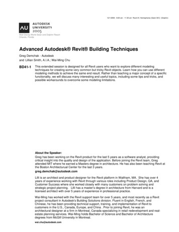
Linking Autodesk Revit Structure and Autodesk Robot Structural Analysis: Beyond the Basics Determine if modeling Boundary Conditions, End Releases, and Loading is more effective in Revit orin the structural analysis software. Some objects like special loads or complex end releaseparameters are available in Robot Structural Analysis Professional software but not in RevitTechniques for modeling complex framingCurved FramingBeamsRevit models curved beams with represented at a true arc; however, like most structural analysissoftware, Robot Structural Analysis Professional requires arcs to be discretized into linear segments. InRevit there are two options to consider when transferring curved beams to Robot.The first approach is to leave the Analytical Beam withits default true arc geometry. The Revit-Robot link willautomatically discretize the arc into linear segments thatare approximately 1 foot in length. This approach is finefor curved beams in isolation; however, thediscretization does not account for intermediatemembers framing into the curved beam. Thus, duplicatenodes may be created and instability introduced into the model.For a better outcome, select the Approximate curve parameter of theAnalytical Beam and indicate the level of discretization. Furthermore,select the Use hard-points parameter to force discretization at thenodes of intersecting framing. These discretized segments will transferto Robot Structural Analysis Professional as shown in Revit.Once the curved beams are transferred to Robot, use the Membersdialog to create “superbars” out of the linear segments. Robot will thenview this “superbar” as a single element for design optimization ratherthan many individual elements.Robot will not transfer the discretized segments back into Revit.Effectively, the Revit-Robot transfer of curved beam in a one-way tripfrom Revit to Robot. Thus, any updates to curved beam will need to bedone manually in Revit.Floors and WallsRevit does not provide curve discretiztion for floor edges and walls likeit does for Beams. Thus, other approaches are needed. Curved Flooredges are discretized in Robot, particularly during finite element Meshgeneration. Since the floor discretization may differ from the beamdiscretization, I suggest modeling the true floor edge offset forAnalytical Model in lieu of in direct alignment with the beam to ensureproper Mesh generation.Alternatively, I suggest modeling two floors or two walls in Revit. One Floor or wall would represent the“physical” model for documentation. Disable the Analytical Model for these. The other Floor or Wall would4
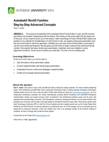
Linking Autodesk Revit Structure and Autodesk Robot Structural Analysis: Beyond the Basicsrepresent the Analytical element. Leave the Analytical Model enabled, but Hide the visibility of the objectin the Documentation views with view filters. These “analytical” versions would be modeled with linearsegments and will transfer to and analyze correctly in Robot.Sloped FramingModeling in RevitLike curved elements, sloped framing adds some complexity to the model. There are many different waysto model sloped floors and framing, but there are a few best practices I suggest for linking with Robot. Model columns with a Top Offset adjustment froma single Level. Create Level lines for eachcolumn line along a slope does not harm, but Ifind it just adds more elements to track in themodel.Consider using the Attach Top/Bottom to attachthe tops of columns to Floor elements.Adjustments made to the Floor slope will adjustthe column top as well.Model Beams with the 3D Snapping optionenabled, which prevents Beams from sticking to Levels.Model Floors for roofs—not Revit’s Roof element. Floors have an associated Analytical Modelelement—Roofs don’t. Additionally, Floors can host corrugated deck—Roofs cannot.Consider using the Slope Arrow tool when defining a sloped Floor since it allows you to define aHeight Offset rather than a slope.Use the Alignment Method: Projection parameter of Analytical Floors to align the analytical plane.Model a separate Floor at changes in slope magnitude and/or direction.Floors with modified with Sub-elements prevent the associated Analytical Floor from adjusting in thevertical direction. Use the Analytical Floor is the slope is very shallow and it is acceptable to notexplicitly model the slope for analysis. Otherwise, model separate Floors or model separate “physical”and “analytical” Floors as similarly described in the aforementioned Curved Framing section.TrussesWorkflowThere is not a truss element in Robot Structural Analysis Professional like there is in Revit. Thus, theRevit-Robot link will transfer the individual truss members of a Structural Truss to Robot. The link will alsoupdate the individual members of the Truss, and leave the overall Structural Truss intact, which is similarto updating a joist that is part of a Beam System.Joists & Joist GirdersWorkflowJoists modeled in Revit can be transferred to and designed in Robot Structural Analysis Professional.Updating the Revit model with new joist sections; however, requires the joist sections to be pre-loaded inRevit before the update. I suggest loading many or all of the joist series into a project during the5
Linking Autodesk Revit Structure and Autodesk Robot Structural Analysis: Beyond the Basicsbeginning of project (or the template if you use joists often) to mitigate this issue. Once the project isdesigned, purge the unused joists from the model.Revit has some joist girder families out of the box, but Robot Structural Analysis Professional does not.Engineers can create a library of joist girders using the Parametric tab of the joist definition tool orperhaps modify the SJI joist library file (XML) to include joist girders. Once Robot and Revit both havejoist girder sections with matching type names, the Revit-Robot link works without issue.Design OptimizationRobot performs design optimization of joists in the same process used for other structural steel. However,since the SJI catalog defines minimum and maximum spans for joists, Robot requires you to start with ajoist type for a particular span that falls between the minimum and maximum spans.Here is an overview of the optimization process for joists: Create a Code Group for a set of joists.Perform the Code Group Optimization using Optimization (by Weight).Click Change All to change the set of joists to a new size. Note, the optimized joist size may need toexist in the project prior to clicking Change All.Joist girders have less standardization than joists, which makes design optimization more of an art basedon Engineer’s judgment. Thus, the design optimization for joists may not be suitable for joist girdersunless you define the joist girders with appropriate parameters in Robot (e.g. Total Load for a given span [ Number of joist spaces – 1 x panel load ] / Span). A better approach may be to have the joist girder inRobot act as an analytical placeholder, and specify the joist girder manually once the support joistreactions are known.Built‐up SectionsWorkflowAny custom Revit families (or types, therein) that are not standard database shapes or created using theRevit Content Generator Extension will not transfer to Robot unless you have also created that shape inRobot. The same rule applies for custom sections created first in Robot—a Revit shape must exist prior tothe transfer.6
Linking Autodesk Revit Structure and Autodesk Robot Structural Analysis: Beyond the BasicsSend and update models between Revit and RobotContent GeneratorUpdating RevitThe Revit/Robot link uses the Content Generator Extension functionality to update the Revit model withchanges made in Robot Structural Analysis Professional. In effect, this is underlying content mappingutility used by the link for standard database elements.It is important to note that the process will change the Revit family in addition to the element. Since thefamily is changed, other dependencies are also affected including custom family and Shared Parametersand other graphical and primitive (Solids/Voids) characteristics built into custom family. Thus, you have toeither change the family back after the Update, which can take some time, or adjust your content strategyfor structural elements in Revit.Customizing Content GeneratorI suggest tailoring the Content Generator elements to meet your model and structural analysis needs.This requires a re-thinking of content strategy for Revit, at least for structural shapes. Rather than usingthe Load Family tools typically used for loading content in Revit, we will use the Content Generator.The Content Generator files are installed with the Revit Extensions at:C:\Program Files\Common Files\Autodesk tentGeneratorLet’s call this the {AREXContentGenerator} directory for short.7
Linking Autodesk Revit Structure and Autodesk Robot Structural Analysis: Beyond the BasicsThe families that Content Generator uses are located at:C:\Program Files\Common Files\Autodesk Shared\Extensions 2013\Data\FamiliesDrilling down this directory reveals Beam and Column families for standard database section (from AISCand CISC, for example) as well as “parametric” sections, which are customized sections for Steel,Concrete, and Timber.There are three files that may also offer value in terms of es.xmlThis file is used to map the section type to the Revit Family name. Note, descend into the localizeddirectories for additional databases. The US file is shown here yMap.xmlThis file maps section type names and databases. It also includes aliases of section names as s.xmlThis file maps the section Families with the Revit families indicated above.Here is an example of how to customize the wide flange shapes. Make a backup of the Resources.xml file.Define a new Revit Family name by changing the line: item name "I PAR" description "I‐sections (with constant flange thickness)"/ to item name "I PAR" description "Wide Flange (BEJ CG)"/ Make a backup of the Templates.xml file.Define a new Revit Family file by changing lines: Family section "I PAR" element "Beam" type "Beam" dir "Beam" file "DB Beam HEA.rfa"/ to Family section "I PAR" element "Beam" type "Beam" dir "Beam" file "DB Beam W BEJ.rfa"/ And Family section "I PAR" element "Column" type "Column" dir "Column" file "DB Column HEA.rfa"/ to Family section "I PAR" element "Column" type "Column" dir "Column" file "DB Column W BEJ.rfa"/ Make a copy of .\Data\Families\Profiles\DB\Beam\DB Beam HEA.rfa and name itDB Beam W BEJ.rfaModify the DB Beam W BEJ.rfa file to suit company standards.8
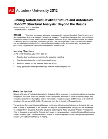
Linking Autodesk Revit Structure and Autodesk Robot Structural Analysis: Beyond the Basics Repeat this operation for the Column family as well.I suggest modifying the content shipped with the Content Generator rather than replacing them outright.The Content Generator families have additional parameters that are not included with the typical Revitfamilies.Consider making similar customizations to the Materials and Rebar settings in Content Generator. Butalways perform testing of the customizations before rolling out a change in a production environment.Finally, update the Revit project template by replacing the appropriate families with the new ContentGenerator families.Analysis and Design ParametersPanel SettingsPanel elements (Floors and Walls) have more analyticalparameters in Robot Structural Analysis Professional thanin Revit, which define criteria for rebar and/or how finiteelements are (or are not) generated for a panel. Theseparameters are “preserved” for continuous transfer bymeans of a linked auxiliary Robot file. The location of thisfile is shown in Revit’s Project Information.Design ParametersStructural steel and reinforced concrete elements in RobotStructural Analysis Professional have design criteriaparameters like buckling coefficients (Kx, Ky), which arenot defined in Revit. Like panel elements, these designparameters are transferred and stored in the auxiliaryRobot file.9
Linking Autodesk Revit Structure and Autodesk Robot Structural Analysis: Beyond the BasicsSend/update settings for Revit‐Robot analytical linkThe send and update settings are described in more detail in the Integrating Autodesk Revit, RevitStructure, and Robot Structural Analysis Professional white paper found on the BIM and Beam blog.10
Effectively, the Revit-Robot transfer of curved beam in a one-way trip from Revit to Robot. Thus, any updates to curved beam will need to be done manually in Revit. Floors and Walls Revit does not provide curve discretiztion for floor edges and walls like it does for Beams. Thus, other approaches are needed. Curved Floor