Transcription
MECHANICALANCHORS FORSEISMIC BRACINGNFPA 13 seismic bracinganchor load tables
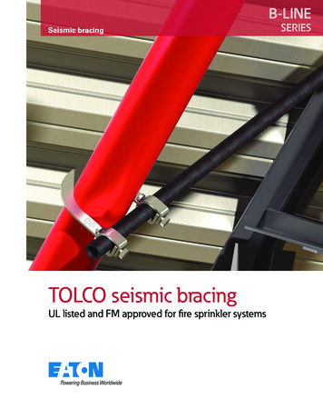
Anchorage for seismic bracing technical supplementHILTI MECHANICAL ANCHORS AND CAST-IN ANCHORS FOR SEISMICBRACING IN ACCORDANCE WITH NFPA 13Hilti post-installed mechanical anchors and single point cast-in-place anchors are common, cost effective methods for attachingboth structural and non-structural elements to concrete base materials. Non-structural elements, such as fire sprinkler pipes;electrical conduit and cable trays; heating, ventilation and air conditioning (HVAC) equipment and ductwork are especially suited forHilti anchoring systems.For fire sprinkler pipe applications, Hilti anchors have been effectively used for many years to support the gravity loaded hangers aswell as the sway bracing for resisting the lateral and vertical motion resulting from seismic loads.Seismic hinge with Hilti anchorSeismic hinge with Hilti anchorFront viewSide viewFigure 1 — Typical sprinkler pipe hanger with seismic sway braceWhile Hilti anchors can be designed and installed to support gravity loads of the pipe through the attachment of the hanger to theconcrete, this document will focus on the design of the anchorage to attach the sway brace assembly to the concrete structure.Contact Hilti for more information related to Hilti anchors to support the vertical pipe hanger.In a seismic event the earthquake forces are resisted by the transverse and longitudinal sway bracing and the sway braces willtransfer the loads through a fastener that is attached to the concrete. In general, the capacity of the fastener in concrete is dictatedby a design per ACI 318-19 Chapter 17, and the design of the sway brace components is dictated by NFPA 13-16 Section 9.3.5(which references ACI 318-11) and NFPA 13-19 Section 18.5 (which references ACI 318-14).Note: For simplicity, this document will reference the 2016 NFPA-13 and 2019 NFPA-13 document sections.This document will not cover the design of the components of the pipe support hangers or sway bracing. Rather, this document willprovide the maximum horizontal load that can be applied to the sway brace, Fpw, based on the Hilti fastener type and embedmentdepth, fastener load capacity, the concrete strength and configuration, the sway brace to fastener connector (seismic hinge)geometry, and the brace angle. See Figure 2 on the following page. Fpw does not consider the adequacy of the seismic hinge orother components of the sway bracing or vertical hanger. The design engineer of record must ensure all of these components aresuitable for the application and design loads.This document is a supplement to the Hilti North American Product Technical Guide, Volume 2, Anchor Fastening TechnicalGuide, Edition 21 (PTG Ed. 21). Please refer to the publication in its entirety, which is available at www.hilti.com or www.hilti.ca, forcomplete details including data development, product specifications, general suitability, installation, corrosion and spacing andedge distance guidelines, for the Hilti anchoring systems noted within.January 20222
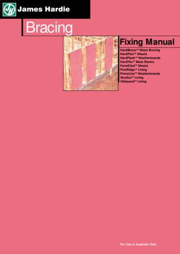
Anchorage for seismic bracing technical supplementFigure 2 — Sway brace load, Fpw, from typical sway brace configuration(Source: NFPA 13 2016 Edition Figure 9.3.5.12.1 and NFPA 13 2019 Edition Figure 18.5.12.1)Horizontal earthquake load design per NFPA-13The maximum horizontal earthquake load, Fpw that will not exceed the allowable capacity of the anchor, can be derived fromNFPA 13-16 Eq. A.9.3.5.12.2a and NFPA 13-19 Eq. A18.5.12.2a:T TallowV 1.2Vallowwhere:T applied service tension load, including the effect of prying Fpw x Pr for all Angle CategoriesFpw horizontal earthquake loadPr prying factor based on fitting geometry and brace angle from vertical as determined from NFPA 13-16 A.9.3.5.12.2and NFPA 13-19 A18.5.12.2Tallow allowable service tension loadV applied service shear load Angle Category A, B, and C: V FpwFpwAngle Category D, E, and F:V tanθAngle Category G, H, and I:V sinθFpwθ brace angle (see Figure 2)Vallow allowable service shear loadT/Tallow shall not be greater than 1.0V/Vallow shall not be greater than 1.0Substituting for T and V for the various angle categories:Angle Category A, B, and C:Fpw PrTallow FpwVallowwhere:Fpw Pr / Tallow 1.0Fpw / Vallow 1.0January 2022 1.2Angle Category D, E, and F:Fpw PrTallow Fpw / tanθVallow 1.2where:Fpw Pr / Tallow 1.0(Fpw / tanθ) / Vallow 1.0Angle Category G, H, and I:Fpw PrTallow Fpw / sinθVallow 1.2where:Fpw Pr / Tallow 1.0(Fpw / sinθ) / Vallow 1.03
Anchorage for seismic bracing technical supplementDesign Tables for Pre-calculated Horizontal Earthquake LoadThe design tables starting on page 8 determine the maximum horizontal load, Fpw, that will satisfy NFPA 13-16 Eq. A.9.3.5.12.2aand NFPA 13-19 Eq. A18.5.12.2a, for various Hilti post-installed and cast-in anchors used in conjunction with various seismic braceswivel attachments to attach the sway brace to concrete.Notes: Tallow and Vallow used as the calculation basis for Fpw in the tables are determined from a strength design calculation according toACI 318-19 Ch. 17 and converted to allowable values per NFPA 13-16 A.9.3.5.12.8.3(D) and NFPA 13-19 A18.5.12.7.3(D). Anchor calculation assumes cracked concrete condition and seismic design category C through F. Minimum edge distance noted in tables assumes a single anchor with one nearby edge with the shear load perpendicular towardthe edge. For an anchor in a corner, the distance to the edge parallel to the direction of the shear must be at least 1.5 times theminimum edge distance noted in the table. Minimum spacing distance noted in tables assumes two anchors in the middle of the concrete with no edge distance reductions. Seismic brace swivel attachment prying factors noted in the tables are from data published according to the following documents Hilti MQS-SP-L-1/2” and MQS-SP-T-1/2” seismic hinge prying factors taken from Hilti Statement on the Prying Factors inregard to Hilti Seismic hinge (all sizes) technical document, dated November 18, 2019. Tolco Figure 909, 910, and 980 swivel brace attachment prying factors taken from Seismic Bracing Anchor Load ChartsB-Line series technical publication, given by Tolco on March 1st, 2021. Prying factors for the Afcon AF075, AF076, AF077, AF771 and AF700 were taken from ASC’s Part Info Sheets for AF075,AF076, AF077, AF771 and AF700 downloaded May 7th, 2021. The above noted documents are subject to change. Contact Hilti for copies of the reference documents noted above. Contact Hilti for copies of the reference documents noted above. TOLCO trademark is owned by Eaton Corporation plc. AFCON trademark is owned by ASC Engineered Solutions. Prying factors are provided that give the highest value for the given angle category. The corresponding value of Pr and Fpw will beconservative for the other angles within the angle category. For angle categories D to I, the angle, θ, is selected that leads to the highest value for the applied shear load, V. Thecorresponding value of Fpw will be conservative for the other angles within the angle category. θ 30 for Angle D and G, θ 45 for Angle E and H, and θ 60 or 75 for Angle F and I. Fpw does not consider the adequacy of the seismic hinge or other components of the sway bracing or vertical hanger. The designengineer of record must ensure all components are suitable for the application and design loads. Values in tables are applicable for noted concrete compressive strength and for concrete with higher compressive strengths. For applications outside of the above noted parameters, contact Hilti for assistance.January 20224
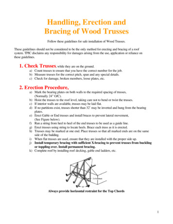
Anchorage for seismic bracing technical supplementDesign Example:We will use a carbon steel 1/2-in. diameter x 3-1/4-in. effective embedment depth Hilti KWIK Bolt TZ2 (KB-TZ2) expansion anchorto attach a Hilti seismic lateral brace into 3,000 psi normal weight concrete. We will assume the concrete is cracked for the seismicdesign. We will assume the anchor is in the middle of a concrete slab (no edge or anchor spacing influence). We will use a HiltiMQS-SP-L-1/2” seismic hinge with a brace angle of 45 degrees (Angle B) attached to the underside of the concrete. Prying factorfor this specific hinge in angle category B is 1.580.The LRFD tension and shear capacity of the KB-TZ2 is determined through a calculation per ACI 318-19 Ch. 17 based on thedesign variables from ICC-ES ESR-4266. A design using the Hilti PROFIS Engineering design software yielded the following LRFDcapacities (design is performed in cracked concrete with seismic reduction factors per ACI 318-19 17.10.5.4):TLRFD 2,660 lb.VLRFD 4,471 lb.To convert the values to an Allowable Stress Design (ASD) value, multiply the LRFD value by 0.43 (NFPA 13-16 A.9.3.5.12.8.3(D))or NFPA 13-19 A18.5.12.7.3(D).Tallow 2,660 0.43 1,144 lb.Vallow 4,471 0.43 1,923 lb.We will calculate a maximum horizontal shear, Fpw 631 lb. Thus:Fpw PrTallowFpw Vallow631 1.580 1,144 631 1.201,923 1.2 OKFpw Pr / Tallow 631 1.580 / 1,144 0.87 1.0 OKFpw / Vallow 631 / 1,923 0.33 1.0 OK Maximum horizontal load, Fpw 631 lb.Alternatively, the maximum horizontal load, Fpw, can be determined from the shortcut tables starting on page 8. Going to page 8, Fpwcan be selected as shown (refer to the Hilti MQS-SP-L-1/2” table, using Angle B, for the 1/2x3-1/4 KB-TZ2 anchor).Effectiveembed.Min.edgedistanceinA30 -44 Pr4.100B45 -59 Pr1.58060 -74 Pr0.870C75 -90 Pr1.850Hilti MQS-SP-L-1/2” and MQS-SP-T-1/2”DEF30 -44 45 -59 60 -74 75 -90 PrPrPrPr1.5202.3202.9003.440G30 -44 Pr3.710H45 -59 Pr2.62060 -74 Pr2.140I75 -90 541in. ex M tanc1.5 disgeedVallowMindis . e dtan geceFigure 3 - Flat Slab Concrete InstallationsJanuary 2022230TallowMin. co nc.thick ne ssTallowMinp.sac5/8" kness3,000 psi minimumlightweight concrete3" max.inMin.spacingdistanceMin. co nc.thick ne ssNominalanchordia.3-7/8"min.3-7/8"min.Min. 12" typicalMin. edge distanceFigure 4 - Lightweight Concrete Over Metal Deck Installations5
Anchorage for seismic bracing technical supplementCONTENTSCARBON STEEL KWIK BOLT TZ28The Hilti KB-TZ2 is the most versatile anchor of the group and is most often used for pipe supportsin seismic areas. The design capacity is the best of its class while remaining a cost effective solutionthat is easier to install. The anchor is available in 3/8-in.to 3/4-in. diameters and is supported byICC-ES ESR-4266 and has FM and UL listings for fire-sprinkler applications.3,000 psi flat slab concrete84,000 psi flat slab concrete95,000 psi flat slab concrete106,000 psi flat slab concrete113,000 and 4,000 psi lightweight concrete over metal deck2-in. and 3-in. deck profiles (i.e. W2, W3)1212KB113The Hilti KB1 is a cost effective wedge anchor similar to the KB-TZ2, and can also be used for pipesupports in seismic areas. This anchor is available in 3/8-in to 3/4-in diameters and is supported byIAPMO ER 678 and has FM and UL listings for fire sprinkler applications.3,000 psi flat slab concrete134,000 psi flat slab concrete145,000 psi flat slab concrete156,000 psi flat slab concrete163,000 and 4,000 psi lightweight concrete over metal deck2-in. and 3-in. deck profiles (i.e. W2, W3)1717KCM-WF/-PD18The KCM-WF/-PD cast-in anchor has multiple internal threads for ultimate flexibility for many pipesizes and is intended for flat concrete slabs. The anchor is available in 1/4-in. to 3/4-in. inner threaddiameters (3/8-in to 3/4-in. diameters are applicable for seismic bracing) and is supported by ICC-ESESR-4145 and has FM and UL listings for fire-sprinkler applications.January 20223,000 psi flat slab concrete184,000 psi flat slab concrete195,000 psi flat slab concrete206,000 psi flat slab concrete216
Anchorage for seismic bracing technical supplementCONTENTSKCM-MD22The KCM-MD cast-in anchor has been optimized for installation in concrete over metal deckapplications. With a short plate option for direct installation on the deck or a long plate option to spanthe lower flutes, the KCM-MD has tremendous flexibility for the fire sprinkler pipe installer. Short plateanchors are shown in this supplement. The KCM-MD is supported by ICC-ES ESR-4145 and has FMand UL listings for fire-sprinkler applications.3,000 and 4,000 psi lightweight concrete over metal deck2-in. and 3-in. deck profiles (i.e. W2, W3)KCC-WF222223The KCC-WF quick push-to-connect technology offers ultimate productivity and is intended for flatconcrete slabs. The anchor is available in 3/8-in. and 1/2-in. diameters and is supported by ICC-ESESR-4145 and has FM and UL listings for fire-sprinkler applications.3,000 psi flat slab concrete234,000 psi flat slab concrete245,000 psi flat slab concrete256,000 psi flat slab concrete26KCC-MD27Pre-assembled self-tapping screws reduce the installation time of the KCC-MD and color-codedplastic plugs protect the inner threads from concrete, sprayed-on fireproofing, and sprayed-oninsulation The anchor is available in 3/8-in. and 1/2-in. diameters and is supported by ICC-ES ESR4145 and has FM and UL listings for fire-sprinkler applications.3,000 and 4,000 psi lightweight concrete over metal deck2-in. and 3-in. deck profiles (i.e. W2, W3)2727HILTI MQS-SP-L-1/2” AND MQS-SP-T-1/2”The Hilti Seismic Hinge MQS-SP is a versatile and quick connect solution for seismic bracingattachments. FM rated for seismic solutions for the lateral or transversal brace assembly. ContactHilti for more information on the seismic hinge and other Hilti pipe support solutions.For comprehensive information on the above noted anchors reference the Hilti North American Product Technical Guide, Volume 2: Anchor Fastening Technical Guide,Edition 21, or the above noted ICC Evaluation Service reports.January 20227
Anchorage for seismic bracing technical supplementMaximum allowable pipe horizontal load, Fpw (lb) carbon steelHilti KWIK Bolt TZ2 in 3,000 psi normal weight cracked chordia.in1/25/83/4Nominalanchordia.in1/25/83/4A30 -44 Pr4.100123166232279B45 -59 Pr1.580267359551631A30 -44 Pr2.490167255280191257383445442567617567703772B45 -59 2A30 -44 Pr2.930147224247167226325389375482533482598656B45 -59 -1/265-1/26860 -74 Pr0.87038852283793760 -74 460 -74 849CCC75 -90 Pr1.850239321487561Hilti MQS-SP-L-1/2” and MQS-SP-T-1/2”DEF30 -44 45 -59 60 -74 75 -90 98481406329277538471394333G30 -44 Pr3.710119160243280H45 -59 Pr2.62016822734439760 -74 Pr2.14020627842248675 -90 lco Figure 909 seismic braceDEF30 -44 45 -59 60 -74 75 -90 2960772636863113495778991812161051866G30 -44 Pr2.710130197213148199309352379459493492581623H45 -59 Pr1.92018327830120928243649753664869669582087960 -74 Pr1.5702243413692563455346086567938528511004107675 -90 3Tolco Figure 910/980 seismic braceDEF30 -44 45 -59 60 -74 75 -90 2833717628100398988977810621064976855G30 -44 Pr1.920160243261183247393441491583623639743791H45 -59 Pr1.3602273443682593495556236948248809031050111860 -74 9A30 -44 Pr2.520189254378441B45 -59 Pr1.070344463730824Afcon AF075/AF076/AF077 seismic braceCDEFG60 -90 30 -44 45 -59 60 -90 30 -44 394290387303198610461597424306695518681508348H45 -59 Pr1.940208280433493I60 -90 Pr1.590254342529603A30 -44 Pr4.170121164229274264339374339420461B45 -59 Pr2.000225303458529550680736706856924C60 -90 Pr0.96036749478688398211671245127814861583Afcon AF771 seismic braceDEF30 -44 45 -59 60 -90 92815802650G30 -44 Pr1.930183246391440489581621637741789H45 -59 Pr1.36025934955562369482488090310501118I60 -90 Pr1.11031742868076485010101078110612861369A30 -44 Pr2.550187252374436431554605554687754B45 -59 Pr1.09034045872181589510711146116413611453C60 -90 Pr0.910378509813912102012081288132815411639Afcon AF700 seismic braceDEF30 -44 45 -59 60 -90 87510151185962G30 -44 Pr1.830188254405455508602642662768817H45 -59 Pr1.29026736057464472085390993810881157I60 -90 Pr1.06032643970178687810411109114313271411III75 -90 Pr1.92023031047054175 -90 Pr1.4002513814132863865986817348879549531124120575 -90 31 Refer to Figure 3 for flat slab concrete installation.January 20228
Anchorage for seismic bracing technical supplementMaximum allowable pipe horizontal load, Fpw (lb) carbon steelHilti KWIK Bolt TZ2 in 4,000 psi normal weight cracked ominalanchordia.in1/25/83/4A30 -44 Pr4.100143192268322B45 -59 Pr1.580308415613699A30 -44 Pr2.490193284312220297431499510640694655805828B45 -59 47A30 -44 Pr2.930169251276193261376438433557608557690714B45 -59 129-3/411-1/414-1/4in5555-1/255-1/265-1/26860 -74 Pr0.870448603915101860 -74 8260 -74 943CCC75 -90 Pr1.850275371545625Hilti MQS-SP-L-1/2” and MQS-SP-T-1/2”DEF30 -44 45 -59 60 -74 75 -90 29526457379320585527455384G30 -44 Pr3.710137185272312H45 -59 Pr2.62019526238544160 -74 Pr2.14023832147154075 -90 9Tolco Figure 909 seismic braceDEF30 -44 45 -59 60 -74 75 -90 2210748917359491261110591196912921143942G30 -44 Pr2.710150216233171230343388424509545551646661H45 -59 Pr1.92021130532924132548454859871977077891293460 -74 Pr1.5702583734022953985926717328799429511116114375 -90 71Tolco Figure 910/980 seismic braceDEF30 -44 45 -59 60 -74 75 -90 9936828725109411061026899111611351061929G30 -44 Pr1.920185264281212285431481543640681708818835H45 -59 0 -74 6A30 -44 Pr2.520218294427494B45 -59 Pr1.070397535804902Afcon AF075/AF076/AF077 seismic braceCDEFG60 -90 30 -44 45 -59 60 -90 30 -44 455334446350228676506663489339767564752587384H45 -59 Pr1.940240323480544I60 -90 Pr1.590293395587665A30 -44 Pr4.170140189264317305391432391485501B45 -59 Pr2.000260350513590624762823808961987C60 -90 Pr0.960423570862962108612801362141616351671Afcon AF771 seismic braceDEF30 -44 45 -59 60 -90 83863859706G30 -44 Pr1.930211284429480541638679705815833H45 -59 Pr1.360299403609680767904962100011551180I60 -90 Pr1.11036649474683394011081178122514151446A30 -44 Pr2.550216291423490498628681640789812B45 -59 Pr1.09039352979489299411801259129415031538C60 -90 Pr0.910437588891992112613241406146916921729Afcon AF700 seismic braceDEF30 -44 45 -59 60 -90 2291011106912601046G30 -44 Pr1.830218293444495561660701732843861H45 -59 Pr1.290308415629701795935993103711951220I60 -90 Pr1.06037650776785597011401211126514571489III75 -90 Pr1.92026635852660275 -90 75 -90 181 Refer to Figure 3 for flat slab concrete installation.January 20229
Anchorage for seismic bracing technical supplementMaximum allowable pipe horizontal load, Fpw (lb) carbon steelHilti KWIK Bolt TZ2 in 5,000 psi normal weight cracked a.in1/25/83/4Nominalanchordia.in1/25/83/4A30 -44 Pr4.100159215300360B45 -59 Pr1.580345464665754A30 -44 Pr2.490215309337246332472544570700758732882873B45 -59 15A30 -44 Pr2.930189274300216291414479484614666622772761B45 -59 255-1/265-1/26860 -74 Pr0.870501674978108260 -74 75260 -74 2016CCC75 -90 Pr1.850308415593677Hilti MQS-SP-L-1/2” and MQS-SP-T-1/2”DEF30 -44 45 -59 60 -74 75 -90 56562499424358622574509429G30 -44 Pr3.710154207296338H45 -59 Pr2.62021829341947860 -74 Pr2.14026635951358575 -90 1Tolco Figure 909 seismic braceDEF30 -44 45 -59 60 -74 75 -90 8887116999782110181366123510181010135312191005G30 -44 Pr2.710167231248191257370417460550588599699692H45 -59 Pr1.92023632635127036452358965077683084698797860 -74 75 -90 741Tolco Figure 910/980 seismic braceDEF30 -44 45 -59 60 -74 75 -90 102810219268111167120311471005115811911132991G30 -44 Pr1.920207279297237319461513585686727764878870H45 -59 60 -74 06A30 -44 Pr2.520244328467539B45 -59 Pr1.070444598863964Afcon AF075/AF076/AF077 seismic braceCDEFG60 -90 30 -44 45 -59 60 -90 30 -44 509374499391255731541717547366825600810656413H45 -59 Pr1.940268361519585I60 -90 Pr1.590328441634715A30 -44 Pr4.170157211295354340437483437542535B45 -59 Pr2.00029139255964068383089588510491038C60 -90 Pr0.9604736389231025117113711455152817551741Afcon AF771 seismic braceDEF30 -44 45 -59 60 -90 64901905754G30 -44 Pr1.930236318460511583683725761875868H45 -59 Pr1.3603344506527248279691027107912401230I60 -90 Pr1.110410552798887101311861259132215191506A30 -44 Pr2.550242325463534557687744715865856B45 -59 Pr1.090439591853953107512681349140116191605C60 -90 Pr0.9104886589521056121214151500158318141799Afcon AF700 seismic braceDEF30 -44 45 -59 60 -90 913331130111013201115G30 -44 Pr1.830243328475526604705748789904897H45 -59 Pr1.2903454646737468569991059111812811270I60 -90 Pr1.060421567821910104412201292136315621550III75 -90 Pr1.92029740057265275 -90 075 -90 851 Refer to Figure 3 for flat slab concrete installation.January 202210
Anchorage for seismic bracing technical supplementMaximum allowable pipe horizontal load, Fpw (lb) carbon steelHilti KWIK Bolt TZ2 in 6,000 psi normal weight cracked 4A30 -44 Pr4.100175235329393B45 -59 Pr1.580377508709802A30 -44 Pr2.490236330359270363507583615752813797949911B45 -59 671A30 -44 Pr2.930207293321237319445515531661716682832797B45 -59 -1/255-1/265-1/26860 -74 Pr0.8705487391030113460 -74 81060 -74 2076CCC75 -90 Pr1.850337455634721Hilti MQS-SP-L-1/2” and MQS-SP-T-1/2”DEF30 -44 45 -59 60 -74 75 -90 80592535465392652614558470G30 -44 Pr3.710168227316360H45 -59 Pr2
Hilti anchoring systems. For fire sprinkler pipe applications, Hilti anchors have been effectively used for many years to support the gravity loaded hangers as well as the sway bracing for resisting the lateral and vertical motion resulting from seismic loads. Seismic hinge with Hilti anchor Seismic hinge with Hilti anchor