Transcription
12/1/2005 - 8:00 am - 11:30 am Room:N. Hemispheres (Salon B/C) (Dolphin)Walt Disney World Swan and Dolphin ResortOrlando, FloridaAdvanced Autodesk Revit Building TechniquesGreg Demchak - Autodeskand Lillian Smith, A.I.A.; Wai-Ming ChuBD41-1This extended session is designed for all Revit users who want to explore different modelingtechniques for creating some very common but tricky Revit objects. Learn how you can use differentmodeling methods to achieve the same end result. Rather than teaching a major concept of a specificfunctionality, we will discuss many interesting and useful topics, including some tips and tricks, andpossible workarounds to overcome some modeling limitations.About the Speaker:Greg has been working on the Revit product for the last 5 years as a software analyst, providingcritical insight into the quality and design of the application. Before joining the Revit team, Gregattended MIT where he earned a Masters degree in architecture. He has also been teaching Revit atthe Boston Architecturual Center for the last 3 years.greg.demchak@autodesk.comLilli is an architect and product designer for the Revit platform in Waltham, MA. She has over 4years of experience working with Revit through various roles including Product Design, QA, andCustomer Success where she worked closely with many customers on problem solving andstrategic project planning. Lilli has a master’s degree in architecture from Harvard and is alicensed architect with over 5 years of experience in professional practice.Wai-Ming has worked with the Revit support team for over 5 years, and most recently as a Revitproject consultant in Autodesk's Building Solutions division. Fluent in English, French, andChinese, he has been providing technical support, training, and implementation of Revit tocustomers in the U.S., Canada, Europe, and China . Prior to joining Revit, he was anarchitectural designer at a firm in Montreal, Canada specializing in retail redevelopment and realestate planning services. Wai-Ming holds Bachelor of Science and Bachelor of Architecturedegrees from McGill University in Montreal.wai.chu@autodesk.com
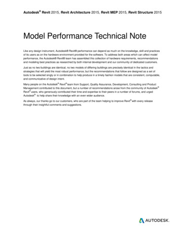
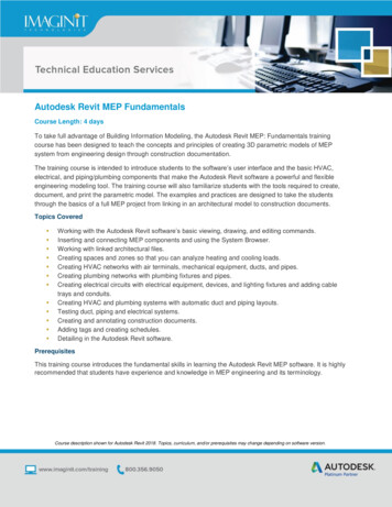
BD41-1 Advanced Autodesk Revit Techniques1Curtain Walls/StorefrontFigure 1: Curtain wall variationsIntroductionCurtain walls provide an incredible amount of flexibility and can be constructed with relative ease using a matrix ofparameters and components. (Figure 1) From standard store front to complex glazing systems, using AutodeskRevit Building provides tools to let you explore and design for a wide range of façade types.When thinking of a curtain wall system, we need to think about three primary components: Grids, Mullions, andPanels. Each of these objects interrelates to one another in explicit, logical ways so that making changes to thesystem requires minimal fidgeting with edge conditions between objects. In other words, a change to one objectwill ripple through the system and automatically update the model. Adjusting grid lines will automatically updatethe size and position of mullions and panels. Like many objects in Revit Building, the concept of a host element isused to drive change through a hierarchy of objects. In a curtain wall system, the wall face hosts curtain grids,which in turn host mullions. The third component, Panels, dynamically fill in space between grids and mullions.Looking at type properties, we see that curtain walls can be defined by vertical and horizontal grid patterns,border and internal mullions types, and curtain panels. Grid Patterns establish a spacing format for the wall in twoprimary directions. For curtain walls, these are the Horizontal and Vertical grids. For curtain systems, these arereferred to as Grid 1 and Grid 2.Mullions and panels can also be defined in the type properties, speeding up the process of layout design. Thecomponents are built on the fly as curtain walls are drawn and/or changed. For example, if we make a curtainwall longer, such that new grids are generated, additional mullions and panels will be generated.SelectionMullion and panel selection is made easier by using the right-click context menu. When your mouse is over apanel or mullion, right-click to bring up options for selection based on internal grids, boundary grids, or the entirewall face. If you need to change an entire row of panels this speeds up the interaction tremendously. Note that tochange panels that are defined in the type you need to first unpin the object. If multiple objects are selected thathave their identity pinned down in the type, use the edit menu command, Unpin Position to free them up.GridsGrids are the bones of any curtain system; the matrix off which all subcomponents are suspended. Using type2
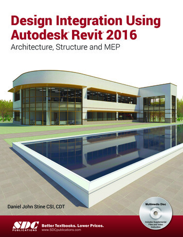
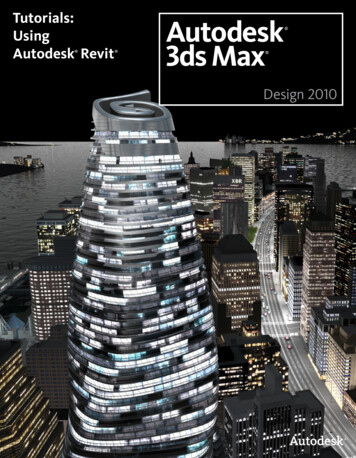
BD41-1 Advanced Autodesk Revit Techniquesdefined grid patterns, curtain walls can be generated very rapidly. Layout rules allow you experiment with spacingwithout having to manually manage individual grid locations.Layout rules for Fixed Distance, Fixed Number, and Maximum Spacing are provided. When fixed distance isset, a spacing value will place a grid at that interval. Fixed number distributes grids across the wall based on adesired number of divisions. Maximum spacing distributes grids based on spacing, but spread the pattern to fit ifthe length of the wall is not a multiple of the spacing value.Additional grids can be added to a type-driven curtain system my placing them manually on the curtain wall face.This allows you to define a major grid pattern and then further refine the pattern with additional grids. Place gridsusing the Curtain Grid tool in the Modeling design pane to achieve A-B-A patterns.Each grid pattern can be rotated on the host face. To rotate a grid, edit the Angle instance parameters inproperties dialog, or select the face of the curtain wall, and press the curtain wall icon to edit the gridconfiguration. Typing in values in the active blue text fields will change the angle of the grids.MullionsMullions can be defined in the type, ormanually placed using the Mullion tool inthe Modeling design pane. Defaultrectangular and corner mullions areprovided in the Revit default template. It isalso possible to create custom mullionprofiles.To make a custom mullion family, open theProfile-Mullion family template. Mullionprofiles can only contain a single closedchain of lines. If you try to make multiplechains, Revit will not accept the profile as avalid mullion type. After loading the profileinto a project, a new mullion type needs tobe made that uses that profile. Once themullion has been made, it can be placed inany curtain system.Figure 2: Custom mullion profile3
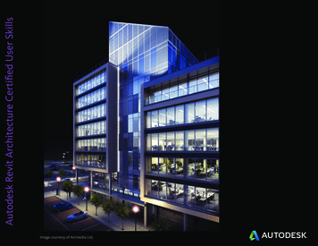
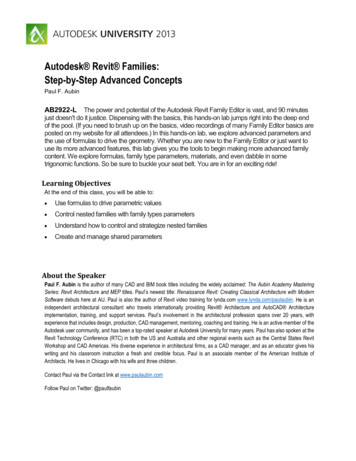
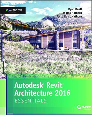
BD41-1 Advanced Autodesk Revit TechniquesPanelsPanels fill in the space between grids andmullions, and can be virtually any shape.Like grids and mullions, a default panel canbe defined in the type properties. Panelscan be swapped out with any other curtainpanels or wall types. If basic wall typesare used as panel, then the wall paneloperates like any other wall in Revit andcan host inserts.A useful, albeit rather hidden parameter,automatically embed, allows a curtain wallto cut out geometry from basic walls. Withthis parameter enabled, it is not necessaryto edit elevation profile sketches to keeptwo walls from overlapping. You can placea curtain wall, and sketch other walls righton top of it. No overlap warning will beissued, and the wall will be carved outperfectly.The most bang for the buck comes fromusing custom panel families, wherecomplex panels can be made to suit avariety of design intents. Custom designedpanel types can be made with the curtainpanel family template. To make curtainpanels that schedule as doors use theDoor – Curtain Wall template. Similarly,use the Window – Curtain Wall templateto make curtain windows.Figure 3: Custom glass and concrete panelsWhen making complex panels withattachment hardware, think of composingthe family using nested families. Figure 2shows panels that make use of nestedfamilies used for clamps and verticalcables.When making nested families, it helps tomake the family workplane based and notbe always vertical. This allows formaximum placement flexibility whenconstruction complex assemblies of nestedobjects.Figure 4: Generic model family parameters4
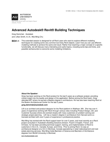
BD41-1 Advanced Autodesk Revit Techniques2Stairs and RailingsStairsRevit provides a sketch based tool for creating stairs. This means that stairs are limited to boundaries that can besketched in one plan view. However, by manipulating type and instance properties and combining more than onestair, a wide variety of stairs can be constructed.Winder StairsAlignment snaps can be very helpful when creating stairs that turn corners. These snaps will help orient the staircorrectly around the corner for the given width. Remember that the run line is drawn at ½ the specified width ofthe stair. To add winders, add diagonal riser lines at the point where the stair turns. Split the boundary linewherever you want the stringer to change slope. You can further control the stringer through the option bar – forexample, you can set segments to be flat or sloped, or have an offset.Spiral StairsStair sketches cannot overlap themselves so arced stair runs are limited to less than 360 . To create a spiral stairthat turns more than 360 , create the stair in 2 parts. The following steps describe how to create a stair that goesup 12’ requiring a revolution of more than 360 .1. Start stair tool and set the arc option on the optionbar2. In the type properties for the stair, turn off Endswith Riser and verify that Maximum RiserHeight is set to 7”3. In stair instance properties, set the base of thestair to Level 1 and the top to Level 1 6’ (half ofthe total distance to be covered)4. Draw run line at ½ the total width of the stair. Theminimum radius is 1’-9”. Be aware that very smallradiuses can force the inside stringer or railings todelete.5. Drag the arc radius to desired location. The initialplacement can be adjusted after placement bydragging the Run line or editing its temporarydimension.6. Remember that you can set the Railing Typebefore creating the stair through the button on thedesign bar.7. Other useful parameters to set in the stair typeare one or both stringers to None.8. Finish sketch9. Start another stair where the last step left off.10. Set the stair instance parameter to base at Level1 6’ and top to Level 2 (or Level 1 12’)11. Create run line similar to above and adjust treadsto match up with first stair segment.Figure 5: Spiral Stair5
BD41-1 Advanced Autodesk Revit TechniquesIf you need to recreate the railing after you make the stair, remember to use the Set Host command to get therailing to follow the stair. You can set the Railing balusters to Use Baluster per Tread on Stairs in the type.Make sure the railing is properly inset so that it overlaps the stairs (and not the stringer) to extend each baluster tothe treads.Figure 6: Three-run stair in 2 partsThree Run StairsAs we saw with spiral stairs, straight run stairs also cannot overlap each other, however by manipulatingparameters and creating 2 stairs on top of each other, you can create a three-run stair. Here’s the basicmethodology:Runs 1 and 2:1. Determine the height of your second landing (in Figure 1 landing height 2/3 the height between Level 1and Level 2)2. Set stair parameters for first 2 runs of the stair to the following:Bottom Level 1Top Level 1 the offset height of the landing3. Start stair tool4. Draw first 2 runs of stair5. FinishRun 3:6. Make it a new type –uncheck Begin with riser in the type7. Set the stair instance parameters for the 3rd run to the following:Bottom Level 1 offset height of the landingTop Level 28. Start a new stair and draw the third run9. Edit first tread to be shape of landing .one edge must be “riser” edge6
BD41-1 Advanced Autodesk Revit Techniques10.11.12.13.14.Set all boundaries of this tread to ‘flat’----in option barFinish sketchEdit rails to correct shape .set to flat- in option bar in sketchFinish railsLanding stringers will be too high - edit the stair sketch and use – “height correction” in option bar to lowerthem15. In stair type use “extend below base” parameter to set bottom of stringer (negative number is down)RailingsRevit provides tools for creating complex railing designs using a combination of layout patterns, profiles,balusters, and panels. The dialog for railing layout can appear daunting, but can in fact be understood.BalustersBalusters are components that get defined in two locations in the Baluster Placement dialog: in the Main patternand for Posts. The main pattern establishes a repetitive baluster placement. The pattern is not limited to onespacing distance, as each baluster in the pattern has a specific distance from the previous baluster. DifferentPosts can defined at start, end and corner locations in the railing. In the example, families for each conditionwere modeled then loaded into a project.Figure 7: End post, center post, corner postThe main Pattern places an instance of a baluster family using the center of the family, and then places anotherinstance using the Dist. from previous value. So, if we want a baluster placed every 4’-8”, we select a baluster touse, then set the distance from previous to 4’-8”. If we want to add an intermediate baluster every 2’-4”, betweenour 4’-8” spacing, we can edit the pattern to place first Balusters 2’-4” from start, then place the intermediatebaluster 2’-4” from that post.Custom balusters are made using the Baluster family template. Balusters are full-fledged 3D geometric objectsthat can be as simple or complex as required. Like any other family made with Revit Building, the baluster can becomposed of nested sub-components, be parameterized to create multiple types, include material parameters,and will schedule.Panels are considered balusters and get placed in pattern using family origin. If a panel is 4’-4” long and has agap between edge of panel and center of post of 2” on each side, the total length of the pattern comes to 4’-8”. Apost starts the pattern, then a panel is placed, and then it repeats. The panel is placed at ½ the length of the totalpattern, 2’-4” from the post center, and then an additional 2’-4” is added to the end of the pattern, at which pointanother post gets placed as the pattern starts over.7
BD41-1 Advanced Autodesk Revit TechniquesFigure 8: Panel SpacingRailsRails use profile families to sweep the length of a railing sketch path. Profiles are 2D chains of lines that form aclosed shape. They can be of any shape or size, including sketches that include splines and ellipses. Rails areplaced based on distance from host plane, and can be shifted horizontally with the Offset parameter. The offsetmoves the rail off the sketch line.3WallsManipulation of the hatch patternIt is possible to re-use the fill pattern definitions that come with the default “out of the box” Revit hatch pattern file:revit.pat. User can always create their new custom pattern by re-scaling it. Once it’s done, the new pattern can beutilized within a material as a surface or cut pattern. Then such material can be incorporated within the structureassembly of the walls, roofs, floors, etc. The following are the procedures to re-use and re-scale the default“Brick” model pattern:8
BD41-1 Advanced Autodesk Revit Techniques1) Go to Settings Fills Patterns2) In the Fill Patterns dialog box, select Modeland press New3) In the Add Surface Pattern dialog box,select Custom4) Press Import and browse to the revit.pat(usually located at C:\ProgramFiles\Autodesk Revit Building 8.1\Data)5) Select Brick, give a new name called MetalSheet and set the Import scale to 46) Press OK twice.7) Create a new material and assign MetalSheet as the Surface Pattern8) Create a new wall type to use the newmaterial9) By using the TAB key, select one of themodel pattern lines and rotate it at yourdesired angleFigure 9: Re-scale and re-name the default Brick patternFigure 10: Changing from corrugated to sheet metal wall materialGlass Block WallsWhat is the best way to create a glass block wall? Some users creates one typical glass block as a family .rfa wallbased component, then load it in a the project file and array such component to create the glass block wall.However, this method could be inefficient and could affect the size and performance of the file. Also, it could bequite tricky if user is trying to create a curved glass block wall.9
BD41-1 Advanced Autodesk Revit TechniquesA good method to create a glass block walls isto define a basic wall type that contains asurface pattern with 2D graphicalrepresentation of a glass block. The followingare the procedures to create a glass block walltype:1) Find a .pat with 2D graphicalrepresentation of a glass block2) In the project, go to Settings FillPatterns, add new model surfacepattern using the .pat file above3) Go to Settings Materials, create anew material called Glass Block. Setyour desired value for Shading Color,Transparency, etc. Add an AccurenderTexture for rendering purposes. AssignGlass Block 8” as Surface PatternFigure 11: Curved and straight glass block walls4) Using Wall command, create a newwall type called Glass Block 8” andassign the above material into the wallstructure.Battered WallsThere are several different methods to create battered wall as illustrated in the example below.Figure 12: Curved battered wallOne of the methods is to create the battered wall as an In Place Family by using one of the Solid Forms, ex.Extrusion, Sweep, etc. When creating an in place wall, it is important to choose Walls as the Family Category andParameters as it will allow user to insert doors and windows.10
BD41-1 Advanced Autodesk Revit TechniquesFigure 13: In Place wall using solid sweepAnother method is to create the battered wall as a vertical compound wall. User needs first to predefine a wallsweep profile .rfa family. Then in the project, user can create a new wall type by assigning the above loadedprofile.Figure 14: Profile added to compound wall structureHowever, when user inserts some doors and windows into the vertical compound battered wall, some oddbehavior may occur, ex. door cuts the entire wall sweep; windows are hidden behind the wall sweep. To resolvesuch problems, user should make the wall sweep cuttable by going back to the Wall Sweeps dialog and check the“Cuttable” box.Figure 15: Make wall sweep "cuttable"Wall DetailingWhen creating details, user can always take advantage and detail directly from the model objects. Such modelbased details are created in model views (ex. section or callout) and are directly based on building modelgeometry. These details do update with changes to the building model, as there is parametric linkage to any11
BD41-1 Advanced Autodesk Revit Techniquesbuilding model components. If necessary, user can always add some detail components to complete the detailswith more accuracy.An example to illustrate the above concept is to create a building foundation sill and footing detail.Figure 16: Building foundation and footingSuch detail can be built quickly by using various Revit model objects such as: 1- Compound wall that user canextend down the outer wall layer to the foundation; 2- Floor that includes the thickness of joist and sub-flooring; 3Stacked walls containing sill plate and foundation; 4- Continuous footing attaching to the base of the foundation.User can always join all geometries to enhance the graphics of the entire detail.To complete such detail with more precision, user can add detail components to the detail that represents siding,lumber, anchor bolt, insulation and break line. These detail components added to the view are two-dimensionalfamily objects. They are also view specific that means only visible in this view.Figure 17: Model based foundation sill and footing detail12
BD41-1 Advanced Autodesk Revit Techniques4RoofsRoofs that slope to one pointCreating a roof that remains a specified height at 3 corners, but dips down at just one corner is a very commonsituation in commercial buildings, but can be hard to model in Revit. Below are two methods of creating this kindof roof.Figure 18: Structure with two methods of modeling the roof1. Roof by Face. The first example is a true warped plane using face based massing. Think about the 2 differentsections that combine to make this roof and create a Mass of the form using a blend. Once you’ve made themass, you can use it to create a face based roof.Figure 19: Face based roof creation using a blend2. Footprint Roof. The second method uses foot print roofs. Foot print roofs must be planar, so this methoddoes not create a true warped roof. Instead, it introduces a crease in the roof. Create 2 triangular sections ofroof. Create a slope arrow and designate heights for the head and tail. Foot print roofs are extruded upperpendicular to their plane, so the top of the roof will be higher than the designate height of the slope arrow atthe top face of the roof.13
BD41-1 Advanced Autodesk Revit TechniquesFigure 20: Footprint roofFigure 21: Footprint roofwith slope arrowmirrored to complete bayOverlapping Eave ReturnsRevit currently limits adjacent sketch lines of footprint roofs to be at the same eave height. However, architectsoften want to return one roof with a lower eave height below another. Figure 5 shows a footprint roof as originallysketched. The orange lines indicate the desired roof. Using in-place void cuts, small supplemental roofs andJoin Geometry, the desired roof can be constructed. (Figures 6 and 7).Figure 22: Foot print roof withFigure 23: Modified roofsadjacent eave heightswith returning eaves14
BD41-1 Advanced Autodesk Revit TechniquesFigure 24: Roof cut with in-place cut extrusion and additional “filler” roofs addedGable End Eave ReturnsGable end eave returns, sometimes know as a “Pork Chop” can be tricky to model in Revit. One commonmethod of achieving the return is to make a small secondary roof combined with a soffit.Integrating roofs into a projectA wide variety of shapes can be created using combinations of footprint, extrusion, face based, and in-placeroofs. Remember that you can make walls follow a broad base of roof forms by using the Attach command onthe option bar.Figure 25: Use Attach Top to attach walls to any roofDormersThere are 3 types of roof cuts in the Openings tool. Roofs can be cut vertically, perpendicular to their face, or adormer opening which makes both horizontal and vertical cuts. (Figure 8) Making a dormer cut that extends to15
BD41-1 Advanced Autodesk Revit Techniquesthe edge of a roof can be confusing. Dormer sketches that extend to the edge of a roof can be left as open loopsas long as they extend to the edge of the roof.Figure 26: Dormer opening cutwith horizontal and vertical cutsFigure 27: Dormer cut sketch linescan extend to the edge of roofthat is being cutBay RoofsWhen using the slope defining line method tocreate a bay roof, such roof may not begenerated properly as Revit simply tries toslope all the surfaces together that won’t meetat a common point. As the result, some strangeand multiple roof ridges will be created causingthe bay roof to look incorrect (See Figure 16).Instead of modeling such roof using the slopedefining line method, user should create it withthe “Slope Arrow” feature. Slope arrow allowsuser to define the height of the tail and head ofthe arrow. Also, user can position veryprecisely on the plan the location of the arrow.Below are the steps to create the bay roofusing the slope arrows.Figure 28: Using slope defining linesproduces undesirable result1) Determine the location of the apex (highestpoint of the roof).2) Determine the height of the apex and itsoffset distance from the front and side edges ofthe roof16
BD41-1 Advanced Autodesk Revit Techniques3) On the plan view, within the roof sketchmode, draw the slope arrows perpendicularlystarting from the bay edges sketch lines towardyour desired apex location. (Figure 16)4) Go to the Properties of the slope arrow andset the “Height Offset at Head” value to theapex height, ex. 10’-0”5) Press “Finish Roof” and see the resultFigure 29: Use slope arrowsFigure 30: Resulting roofVaulted RoofsSome complex roofs or ceilings cannot be modeled directly with Roof and Ceiling commands. Although user canbuild some curved surface roofs using Roof by Extrusion, however Ceiling command in can only generate flatsurface geometry. If user wants to model some irregular shapes of roofs and ceilings (ex. vaulted or cathedral),user can use the In Place Family method by using one of the Solid Forms, ex. Sweep (See Figure 21).Figure 31: In-place vaulted roofWhen creating an in place roof or ceiling, it is important to choose the appropriate Family Category andParameters. For example, if the geometry created is assigned as the Roofs family category, any system walls canbe attached to the selected in place roof. If the geometry created is assigned as the Ceilings family category, anyceiling based lighting fixture components can be inserted into the selected in place ceiling. Also, the geometry willbe classified in the correct schedule category.17
BD41-1 Advanced Autodesk Revit TechniquesComplex RoofsTwo separated individual roofsFigure 32: Overlapping roofsThe following are some useful Revit tools to clean up the model when roofs fail to join together:1) User can use in place Void Form to remove some unwanted or surplus parts of the roof (Figure 20).Figure 33: In place voids to remove the unwanted parts of the roofs2) Use Join Geometry tool to make appear roofs intersecting lines in Hidden Line mode.5SiteProject ElevationsWhen working in a Revit project, one of the most common errors committed by users is to go to an elevation view,try to change directly the project level elevation to match the sea level value (See Figure 31). This methodology isnot recommended and should be avoided.Rather than modifying and moving the actual level line, instead user is encouraged to use the “Relocate thisProject” command. This feature will allow user to relocate the movable shared coordinate “space” behind theRevit model in order to display the sea level value properly. Below are the steps for using the “Relocate thisProject” feature:1) On the elevation view, under the Tools menu, search for Project Position/Orientation and select “Relocate thisProject”2) Click on the Level 1 line, move the mouse cursor up, type and change the temporary dimension to 2372’-0”18
BD41-1 Advanced Autodesk Revit TechniquesFigure 34: Relocate the movable shared coordinate “space” behind the Revit model3) Zoom to Fit and observe the Level 1 elevation. It is still displaying the Revit project coordinate which is 0’-0”.4) Click on the Level 1 line and go to its Properties.5) Press Edit/New and change the “Elevation Base” parameter value from Project to Shared, press Ok twice (SeeFigure 34).Figure 35: Set the Elevation Base to SharedFigure 34: Set the Elevation Base to Shared6) Zoom into the Level 1 line to see the resultFigure 36: Level lines displaying the sea level value properlyWhen working in a Revit project, it is more convenient to model the building orthogonally which is facing bydefault to the Project North situated at the upper direction of the screen. Also, the Revit Project North is located atcertain angle from the True North in reality (See Figure 36).19
BD41-1 Advanced Autodesk Revit TechniquesOrientation to True NorthFigure 37: The Project North is 45 east with respect to True North in realityWhen creating a site plan, user often needs to get the building oriented correctly with respect to True North.Rather than rotating the actual building with respect to the True North, user should instead utilize the “Rotate TrueNorth” command in order to rotate the building with respect to the True North. Below are the steps for using the“Rotate True North” feature:1) Right-click in the desired plan view and click View Properties. Set the Orientation parameter to True Northand click OK (See Figure 37).Figure 38: Set the Orientation to True North2. On the Tools menu, choose Project Position/Orientation, select Rotate True North (See Figure 38).Figure 39: Rotate True North command3. Use the above command just like the regular Rotate command. Rotate the project graphically in the viewto True North or enter the angle (ex. 45 ) and direction from True North on the Options Bar. Once it’sdone, take a look on the result (See Figure 39).Figure 40: Building oriented correctly with respect to the True North20
Advanced Autodesk Revit Building Techniques This extended session is designed for all Revit users who want to explore different modeling techniques for creating some very common but tricky Revit objects. Learn how you can use different modeling methods to achieve the same end r