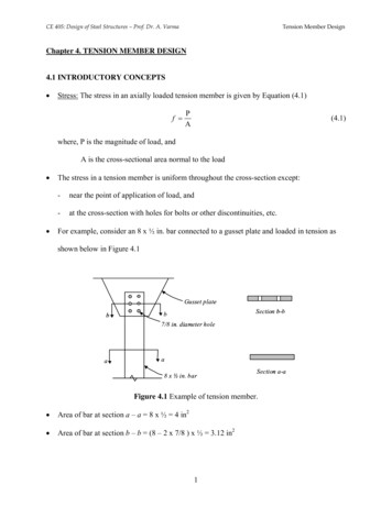
Transcription
LIGHT GAUGE STEEL FRAMED STRUCTURESTECHNICAL MANUALVersion 1.0 09/18
Introduction toMetStructures Limited formedin 2017 following decades ofexperience in the Hot Rolled andCold Formed Construction markets.“Specialists in providing off site solutionsfor Building Structures, reducing onsite activities and improving safety,programme, quality and cost.”We are a construction company providing Design,Manufacturing and Installation services for a wide range ofstructures across many market sectors.Our in-house teams are ready to support your project anywherein the UK and Ireland, providing a full consultation fromconception, design and pricing, offsite manufacturing andpanel assembly, installation and completion on site.We offer a wide scope of works including: Hot Rolled Fabricated Steelwork Stairs and Handrailing Light Gauge Steel Framing Mezzanines Flooring Systems SFSThe following Technical Manual provides details of our Light Gauge Steel Framing systemspecifically developed for the residential, hotel, care and student accommodation sectors.The system has been fully assessed by the SCI and NHBC for structural designs up to 15 storeysin accordance with BS EN 1993-1-3.02 www.metstructures.uk.com 0121 389 1603
CONTENTS1. SYSTEM PRINCIPLES& ADVANTAGES 1.1 /System Summary 1.2 / Intended Use & Range of Application 2.11 / Hot Rolled Steelwork 0404–05061.3 / Building Engineering Physics 06–151.3.1 /Warm Frame & Rapid DryEnvelope (RDE) 06–071.3.2 /Fire Resistance 1.3.3/Acoustic Performance 08–101.3.4 /Thermal Performance 101.3.5 /Cladding Case Study /Hinton Road, Bournemouth 1.4 / Project Services 0810–1515161.4.1 /Concept Design Support & Review 161.4.2/Detailed Design 161.4.3 /Manufacture 171.4.4 /Installation 171.4.5 /Operation & Maintenance 171.5 / Project Lead Times 2. SYSTEM OVERVIEW 1819282.11.1 /Integration Within The Panel 292.11.2/Free Standing Columns 292.11.3 /Beams Within Floors 302.11.4 /Surface Coatings 302.12 / Finishes 302.13 / Services 312.14 / Pods 323. STANDARD COMPONENTS 333.1 / Standard Cold Rolled Sections 333.1.1 /Cold Rolled Parts MC Profile 333.1.2/Cold Rolled Parts MU Profile 334. DESIGN PRINCIPLES 344.1 / Disproportionate Collapse 344.2 / Bracing & Frame Stability 344.3 / Load Paths & Load Tracing 344.4 / Window/Door Opening Guidance 354.5 / Accuracy & Tolerances 352.1 / Design Life 194.5.1 /Section Accuracy 352.2 / Maintenance 194.5.2/Site Tolerance 362.3 / Disposal 194.5.3 /Frame Installation Tolerances 362.4 / Sustainability 194.5.4 /Follow-On Trade Tolerances 362.5 / Foundations 202.6 / Panels 205. STANDARD DETAILS 372.7 / Floors 21Detail Contents 372.8 / Roofs 21Standard Details 2.9 / Lifts 222.9.1 /Lift Design Requirements 2.10 / Stairs 38–6522232.10.1 /Basics 2.10.2/Single Flight Arrangements 23–24242.10.3 /Double Flight Arrangements 252.10.4 /Other Stair Arrangements 252.10.5 /Stair Attachment 2.10.6 /Hand Rails & Balustrades 26–27270121 389 1603 www.metstructures.uk.com 03
1. SYSTEM PRINCIPLES& ADVANTAGES1.1 /SYSTEM SUMMARYThe MetStructures Framing System is a structuralsolution for walls, floors and roofs formed fromlight gauge steel shaped sections andtrapezoidal decking with concrete cover.MetStructures profiles are 1.2mm to3.2mm in gauge, roll formed frompre-coated galvanised coil. Sectionsare factory assembled into loadbearing wall panels consisting of a‘U’ base track and ‘C’ vertical studsset at regular centres with ledgersat head to suit the application. TheMetStructures system can be used toform structures up to a maximum offifteen storeys in height dependentupon loading, geometry and usage.Load bearing light gauge steel framingis based on balloon constructionproviding separate storey heightframes. Vertical gravity loads fromroof and floors span onto loadbearing walls down to supportingfoundations or podia. Lateralwind loads applied to the externalenvelope are taken by roofs and floorsusing plate action, then into bracedwalls or cores down to the supportingfoundation or podium.WallFloor/RoofWallFigure 1.Principlesof BalloonConstructionThis construction is most effectivelyused within simple repetitivestructural wall arrangementsbetween storeys, regular floorspans and direct load paths. Morecomplicated structures can alsobe accommodated using transfermembers (e.g. hot rolled beams) orstructures for indirect load paths.Vertical studs are assembled intopanels within the ‘U’ head and basetrack. All joints are assumed to bepinned for simple analysis. Panels arebraced with diagonal flat straps (asrequired by design) and sheathingboard may be factory applied to theexternal walls.Figure 2. Example of Load-BearingFraming (boarding omitted for clarity)04 www.metstructures.uk.com 0121 389 1603
1 SYSTEM PRINCIPLES & ADVANTAGES1.1 /ContinuedPanels are bolted togetheron site through pre-punchedholes and either anchored tothe supporting foundation orscrew fixed to panels below. Allconnections are designed andchecked for disproportionatecollapse tying requirementsderived from the intendeduse and size of the building.Temporary props are fitted forstability during construction.Floors are generally formed fromcomposite concrete deckingwhich is seated on the perimeterprofiles at the tops of theload-bearing wall panels.The deck is then temporarilypropped (if required) and securedusing self-piercing, self-drillingscrews. Reinforcement is laidas per design requirementsfor fire and disproportionatecollapse resistance. Mesh or fibrereinforcement may be used tominimise cracking of the slab.Figure 3. Typical ProfilesOnce the floor has adequately cured, construction ofthe next level begins and loading out of the floorwith plasterboard / bathroom pods, etc. takes place.Where joisted cassette floors are used they are formed in thefactory from deeper ‘C’ sections at regular centres with ‘U’profile end tracks and noggins as required to prevent twistand lateral movement. A working platform of minimum18mm OSB is provided. The joists are designed with pinnedend connections and effective lengths dependentupon the restraints available fromfinishes and noggins.The roof may also be formed from composite concretedecking but can alternatively employ timber or light steelframe trusses or joists. In all instances, floors and roofs areto provide adequate diaphragmatic resistance to distributelateral loads back to the buttressing side wall bracingsystems.Figure 4. Wall and FloorConstruction (Side Fixed)Isometric0121 389 1603 www.metstructures.uk.com 05
1.2 /INTENDED USE & RANGE OF APPLICATIONThe system is suitablefor use on mostconstruction projectsincluding but notlimited to: Residential Student Accommodation Hotels & Hospitality Retirement Living Dwelling Houses GovernmentThe system’s application is currently limited to an absolutemaximum of fifteen storeys. Depending on the structuralrequirements and building type, lower limits may beapplicable. Additionally, as a building product, elements ofthe framing system can be used for special constructionssuch as features, bulkheads and soffits.1.3 /BUILDING ENGINEERING PHYSICSThe MetStructures framing systemmay be used within a wide rangeof building applications.1.3.1 /When such items are to be built in a cold frame environment(uninsulated or exposed to possible water ingress), specialconsiderations such as additional protective coatings maybe required and the lifetime of the construction reducedin accordance with the guidance given by the SCI P262document (The Steel Construction Institute, 2009),BS EN ISO 12944-2:1998 (BSI, 1998) andBS EN ISO 9223:2012 (BSI, 2012).Building engineering physics and fire resistant designrequirements are readily integrated to suit each application.This ensures that the MetStructures framed building meetsthe ratings outlined by the client specification and buildingregulations for environmental performance, user comfortand safety.WARM FRAME & RAPID DRY ENVELOPE (RDE)Internal lining boards (vapour check andfire restraint boards by specification)MetStructures steel studs. Mineral woolinsulation by others to specificationrequirementsFactory fitted external sheathing boardBrick-tie channels fixed to studs throughinsulation and boardsExternal insulationExternal facing brickworkFigure 5.Indicative warm frame wall build-up06 www.metstructures.uk.com 0121 389 1603
1 SYSTEM PRINCIPLES & ADVANTAGES1.3.1 /ContinuedThe cold rolled sections inthe stud and track system aregalvanised with 20μm zinccoating. Its intended use isto be within a ‘warm frameenvironment’, i.e. the steel is toalways be fully enclosed withinthe warm envelope of the façade.To achieve this and to keep theframe warm as well as avoiding coldbridging, insulation is applied to theexternal face of the steel. The amountof insulation that is applied to theoutside of the frame is dependenton the U-Value that is required to beachieved and designed to avoid therisk of interstitial condensation (toarchitect’s specification). Assumingthe steel is maintained within a warmframe environment, current industryguidance is that a design life of 250years can be expected (The SteelConstruction Institute, 2009).Where the steel is installed in a coldframe environment (low risk of wateringress, some risk of condensation),this reduces to 50-60 years.See extract on following page fromSCI Publication P262 (The SteelConstruction Institute, 2009).Design life of galvanised steel sections in common building applicationsProduct applicationEnvironmental conditionsPredicted design lifeWalls and floors in warm frame applicationsNo risk of water ingress or condensation250 yearsNon-load bearing stud partitionsWarm internal environmentand no risk of water ingress250 yearsInfill external walls in multi-storey buildingsWarm frame and no risk of water ingress250 yearsRoof structures (insulated)Low risk of condensation200 yearsSuspended ground floors(with over-site membrane)Low risk of water ingress;some risk of condensation100 yearsRoof structures (uninsulated)Some risk of condensation100 yearsPurlins and side railssupporting metal claddingLow risk of condensation;some dust and pollution60 yearsSub-frames to over-cladding panelsLow risk of water ingress;some risk of condensation60 yearsSuspended ground floors(without over-site membrane)Low risk of water ingress;higher risk of condensation50 yearsNote: All values are for Z275(total weight of zinc coating on both surface 275g/m2)The BRE Report “Thermal Insulation:Avoiding Risks” (BRE REP 262, 2002)discusses aspects of insulationsrelevant to external light steel framewalls. A vapour control layer shouldbe provided unless a condensationrisk analysis is carried out. Thisshould be fixed on the warm sideof the wall insulation and shouldcover the external wall includingbase rails, head rails, studs and linteland cill reveals. The vapour controllayer should be of 500g polyethyleneor vapour control plasterboard asrecommended in the NHBC 6.10 -D6(NHBC, 2018). Insulation shouldFigure 6. Extract from P262- Durability of Light Steel Framingcontinue 150mm below the baserail of the steel wall to minimizethermal bridging. Insulation withan integral facing on one side only,e.g. a foil facing, should have thefacing on the cavity side. The facingshould not be used as the vapourcontrol layer. Service pipes, conduits,etc. within walls should be on thewarm side of the insulation. Designand specification of the wall buildup beyond the steel frame is theresponsibility of the architect or othernominated specialist. In applicationswhere the steel is not in a warm frameconstruction, special considerationsmay be required to ensure thelongevity of the steel.Openings for windows, doors, flues,vents, etc. are formed by designwithin the framed panels and theweights, position and connectionsare considered in the structuralcalculations and drawings.The system adheres to the principlesof Rapid Dry Envelope (RDE) wherethe building is made watertightquickly and to a high standard torelease works on site for internaltrades.0121 389 1603 www.metstructures.uk.com 07
1.3.2 /FIRE RESISTANCEAs cold formed steel members are non-combustiblebut have no significant inherent fire resistance theyare dependent on the through-wall components toprovide the structure’s fire protection.Fire resistance of light gauge steelsystems is provided by single ormultiple layers of boarding fixedto the flange of the studs or joistsThis may be either fixed directlyor via secondary resilient bars.Manufacturers of such boardingsystems have tested their boardsto protect light steel frame systemsfor insulation, integrity and load1.3.3 /resistance to relevant codes ofpractice. Typically, over 90 minutes’resistance may be achieved for eachelement using multiple layers of15mm boards.Fire resistance of the compositeconcrete deck floor is providedby reinforcing the concrete withadequate cover. Supporting channelsat the head of the walls also needto be fire protected to achieve therequired rating.Cavity stopping systems should alsobe employed as required by therelevant building regulations.Further details may be sought fromSCI Technical Information SheetED016 (The Steel ConstructionInstitute, 2012).ACOUSTIC PERFORMANCEPart E of the building regulations defines theminimum requirements for floors and walls thatseparate one dwelling from another, betweeninternal walls and floors from another dwelling orcommunal space.Approveddocument Edescribes twomethods ofdemonstratingcompliance:Acoustic performance must additionally satisfyany regional guidance and suitability requirementswhich must be defined by the design team at thestart of the project. T he use of ‘Robust Details’ (Robust Details Ltd, 2014)This method relies on specific defined build-ups provided by Robust details todemonstrate compliance based on known combinations. P re-completion testingThis method tests elements of the building on site (such as separation of walls andfloors) prior to handover o
the steel is maintained within a warm frame environment, current industry guidance is that a design life of 250 years can be expected (The Steel Construction Institute, 2009). Where the steel is installed in a cold frame environment (low risk of water . ingress, some risk