Transcription
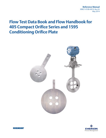
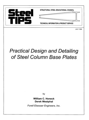
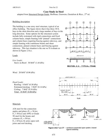
CE 405: Design of Steel Structures – Prof. Dr. A. VarmaTension Member DesignChapter 4. TENSION MEMBER DESIGN4.1 INTRODUCTORY CONCEPTS Stress: The stress in an axially loaded tension member is given by Equation (4.1)f PA(4.1)where, P is the magnitude of load, andA is the cross-sectional area normal to the load The stress in a tension member is uniform throughout the cross-section except:-near the point of application of load, and-at the cross-section with holes for bolts or other discontinuities, etc.For example, consider an 8 x ½ in. bar connected to a gusset plate and loaded in tension asshown below in Figure 4.1Gusset platebSection b-bb7/8 in. diameter holeaa8 x ½ in. barSection a-aFigure 4.1 Example of tension member. Area of bar at section a – a 8 x ½ 4 in2 Area of bar at section b – b (8 – 2 x 7/8 ) x ½ 3.12 in21
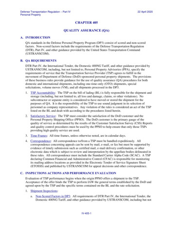
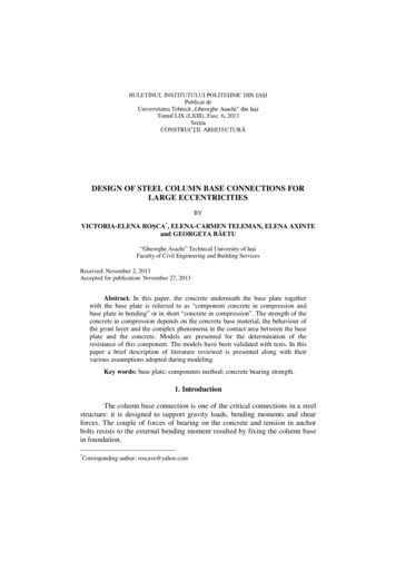
CE 405: Design of Steel Structures – Prof. Dr. A. Varma Tension Member DesignTherefore, by definition (Equation 4.1) the reduced area of section b – b will be subjected tohigher stresses However, the reduced area and therefore the higher stresses will be localized around sectionb – b. The unreduced area of the member is called its gross area Ag The reduced area of the member is called its net area An4.2 STEEL STRESS-STRAIN BEHAVIOR The stress-strain behavior of steel is shown below in Figure 4.2FuStress, fFyEεyεuStrain, εFigure 4.2 Stress-strain behavior of steel In Figure 4.2, E is the elastic modulus 29000 ksi.Fy is the yield stress and Fu is the ultimate stressεy is the yield strain and εu is the ultimate strain2
CE 405: Design of Steel Structures – Prof. Dr. A. Varma Tension Member DesignDeformations are caused by the strain ε. Figure 4.2 indicates that the structural deflectionswill be small as long as the material is elastic (f Fy) Deformations due to the strain ε will be large after the steel reaches its yield stress Fy.4.3 DESIGN STRENGTH A tension member can fail by reaching one of two limit states:(1) excessive deformation; or (2) fracture Excessive deformation can occur due to the yielding of the gross section (for example sectiona-a from Figure 4.1) along the length of the member Fracture of the net section can occur if the stress at the net section (for example section b-b inFigure 4.1) reaches the ultimate stress Fu. The objective of design is to prevent these failure before reaching the ultimate loads on thestructure (Obvious). This is also the load and resistance factor design approach recommended by AISC fordesigning steel structures4.3.1 Load and Resistance Factor DesignThe load and resistance factor design approach is recommended by AISC for designing steelstructures. It can be understood as follows:Step I. Determine the ultimate loads acting on the structure-The values of D, L, W, etc. given by ASCE 7-98 are nominal loads (not maximum orultimate)-During its design life, a structure can be subjected to some maximum or ultimate loadscaused by combinations of D, L, or W loading.3
CE 405: Design of Steel Structures – Prof. Dr. A. Varma-Tension Member DesignThe ultimate load on the structure can be calculated using factored load combinations,which are given by ASCE and AISC (see pages 2-10 and 2-11 of AISC manual). Themost relevant of these load combinations are given below:1.4 D(4.2 – 1)1.2 D 1.6 L 0.5 (Lr or S)(4.2 – 2)1.2 D 1.6 (Lr or S) (0.5 L or 0.8 W)(4.2 – 3)1.2 D 1.6 W 0.5 L 0.5 (Lr or S)(4.2 – 4)0.9 D 1.6 W(4.2 – 5)Step II. Conduct linear elastic structural analysis-Determine the design forces (Pu, Vu, and Mu) for each structural memberStep III. Design the members-The failure (design) strength of the designed member must be greater than thecorresponding design forces calculated in Step II. See Equation (4.3) below:φ Rn γ i Qi(4.3)-Where, Rn is the calculated failure strength of the member-φ is the resistance factor used to account for the reliability of the material behavior andequations for Rn-Qi is the nominal load-γi is the load factor used to account for the variability in loading and to estimate theultimate loading condition.4.3.2 Design Strength of Tension Members Yielding of the gross section will occur when the stress f reaches Fy.f P FyAg4
CE 405: Design of Steel Structures – Prof. Dr. A. VarmaTension Member DesignTherefore, nominal yield strength Pn Ag FyFactored yield strength φt Pn(4.4)(4.5)where, φt 0.9 for tension yielding limit state See the AISC manual, section on specifications, Chapter D (page 16.1 –24) Facture of the net section will occur after the stress on the net section area reaches theultimate stress Fuf P FuAeTherefore, nominal fracture strength Pn Ae FuWhere, Ae is the effective net area, which may be equal to the net area or smaller.The topic of Ae will be addressed later.Factored fracture strength φt Ae Fu(4.6)Where, φt 0.75 for tension fracture limit state (See page 16.1-24 of AISC manual)4.3.3 Important notes Note 1. Why is fracture (& not yielding) the relevant limit state at the net section?Yielding will occur first in the net section. However, the deformations induced by yieldingwill be localized around the net section. These localized deformations will not causeexcessive deformations in the complete tension member. Hence, yielding at the net sectionwill not be a failure limit state. Note 2. Why is the resistance factor (φt) smaller for fracture than for yielding?The smaller resistance factor for fracture (φt 0.75 as compared to φt 0.90 for yielding)reflects the more serious nature and consequences of reaching the fracture limit state. Note 3. What is the design strength of the tension member?5
CE 405: Design of Steel Structures – Prof. Dr. A. VarmaTension Member DesignThe design strength of the tension member will be the lesser value of the strength for the twolimit states (gross section yielding and net section fracture). Note 4. Where are the Fy and Fu values for different steel materials?The yield and ultimate stress values for different steel materials are noted in Table 2 in theAISC manual on pages 16.1–141 and 16.1–142. Note 5. What are the most common steels for structural members?See Table 2-1 in the AISC manual on pages 2–24 and 2-25. According to this Table: thepreferred material for W shapes is A992 (Fy 50 ksi; Fu 65 ksi); the preferred material forC, L , M and S shapes is A36 (Fy 36 ksi; Fu 58 ksi). All these shapes are also available inA572 Gr. 50 (Fy 50 ksi; Fu 65 ksi). Note 6. What is the amount of area to be deducted from the gross area to account for thepresence of bolt-holes?-The nominal diameter of the hole (dh) is equal to the bolt diameter (db) 1/16 in.-However, the bolt-hole fabrication process damages additional material around the holediameter.-Assume that the material damage extends 1/16 in. around the hole diameter.-Therefore, for calculating the net section area, assume that the gross area is reduced by ahole diameter equal to the nominal hole-diameter 1/16 in.6
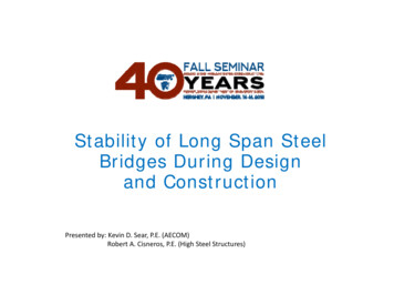
CE 405: Design of Steel Structures – Prof. Dr. A. VarmaTension Member DesignExample 3.1 A 5 x ½ bar of A572 Gr. 50 steel is used as a tension member. It is connected to agusset plate with six 7/8 in. diameter bolts as shown in below. Assume that the effective net areaAe equals the actual net area An and compute the tensile design strength of the member.Gusset platebb7/8 in. diameter boltaa5 x ½ in. barA572 Gr. 50Solution Gross section area Ag 5 x ½ 2.5 in2 Net section area (An) -Bolt diameter db 7/8 in.-Nominal hole diameter dh 7/8 1/16 in. 15/16 in.-Hole diameter for calculating net area 15/16 1/16 in. 1 in.-Net section area An (5 – 2 x (1)) x ½ 1.5 in2Gross yielding design strength φt Pn φt Fy Ag- Gross yielding design strength 0.9 x 50 ksi x 2.5 in2 112.5 kipsFracture design strength φt Pn φt Fu Ae-Assume Ae An (only for this problem)-Fracture design strength 0.75 x 65 ksi x 1.5 in2 73.125 kipsDesign strength of the member in tension smaller of 73.125 kips and 112.5 kips7
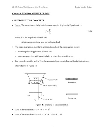
CE 405: Design of Steel Structures – Prof. Dr. A. Varma-Tension Member DesignTherefore, design strength 73.125 kips (net section fracture controls).Example 3.2 A single angle tension member, L 4 x 4 x 3/8 in. made from A36 steel is connectedto a gusset plate with 5/8 in. diameter bolts, as shown in Figure below. The service loads are 35kips dead load and 15 kips live load. Determine the adequacy of this member using AISCspecification. Assume that the effective net area is 85% of the computed net area. (Calculatingthe effective net area will be taught in the next section). Gross area of angle Ag 2.86 in2(from Table 1-7 on page 1-36 of AISC)aL 4 x 4 x 3/ 8d b 5/8 in.Section a-aaGusset plate Net section area An-Bolt diameter 5/8 in.-Nominal hole diameter 5/8 1/16 11/16 in.-Hole diameter for calculating net area 11/16 1/16 3/4 in.-Net section area Ag – (3/4) x 3/8 2.86 – 3/4 x 3/8 2.579 in2 Effective net area Ae 0.85 x 2.579 in2 2.192 in2 Gross yielding design strength φt Ag Fy 0.9 x 2.86 in2 x 36 ksi 92.664 kips Net section fracture φt Ae Fu 0.75 x 2.192 in2 x 58 ksi 95.352 kips8
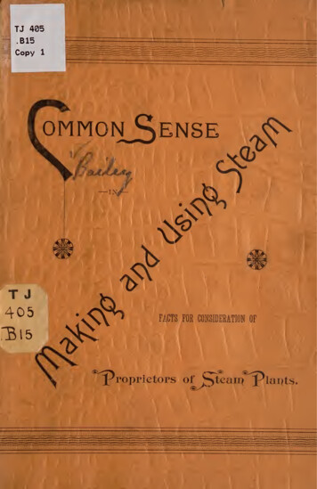
CE 405: Design of Steel Structures – Prof. Dr. A. VarmaTension Member Design Design strength 92.664 kips Ultimate (design) load acting for the tension member Pu-(gross yielding governs)The ultimate (design) load can be calculated using factored load combinations given onpage 2-11 of the AISC manual, or Equations (4.2-1 to 4.2-5) of notes (see pg. 4)-According to these equations, two loading combinations are important for this problem.These are: (1) 1.4 D; and (2) 1.2 D 1.6 L-The corresponding ultimate (design) loads are:1.4 x (PD) 1.4 (35) 49 kips1.2 (PD) 1.6 (PL) 66 kips-(controls)The ultimate design load for the member is 66 kips, where the factored dead liveloading condition controls. Compare the design strength with the ultimate design load-The design strength of the member (92.664 kips) is greater than the ultimate design load(66 kips). φt Pn (92.664 kips) Pu (66 kips)The L 4 x 4 x 3/8 in. made from A36 steel is adequate for carrying the factored loads.4.4 EFFECTIVE NET AREA The connection has a significant influence on the performance of a tension member. Aconnection almost always weakens the member, and a measure of its influence is called jointefficiency. Joint efficiency is a function of: (a) material ductility; (b) fastener spacing; (c) stressconcentration at holes; (d) fabrication procedure; and (e) shear lag.9
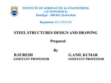
CE 405: Design of Steel Structures – Prof. Dr. A. VarmaTension Member Design All factors contribute to reducing the effectiveness but shear lag is the most important. Shear lag occurs when the tension force is not transferred simultaneously to all elements ofthe cross-section. This will occur when some elements of the cross-section are not connected. For example, see Figure 4.3 below, where only one leg of an angle is bolted to the gussetplate.Figure 4.3 Single angle with bolted connection to only one leg. A consequence of this partial connection is that the connected element becomes overloadedand the unconnected part is not fully stressed. Lengthening the connection region will reduce this effect Research indicates that shear lag can be accounted for by using a reduced or effective netarea Ae Shear lag affects both bolted and welded connections. Therefore, the effective net areaconcept applied to both types of connections. -For bolted connection, the effective net area is Ae U An-For welded connection, the effective net area is Ae U AgWhere, the reduction factor U is given by:U 1-x 0.9L10(4.7)
CE 405: Design of Steel Structures – Prof. Dr. A. Varma-Tension Member DesignWhere, x is the distance from the centroid of the connected area to the plane of theconnection, and L is the length of the connection.-If the member has two symmetrically located planes of connection, x is measuredfrom the centroid of the nearest one – half of the area.-Additional approaches for calculating x for different connection types are shown inthe AISC manual on page 16.1-178.-The distance L is defined as the length of the connection in the direction of load.-For bolted connections, L is measured from the center of the bolt at one end to thecenter of the bolt at the other end.-For welded connections, it is measured from one end of the connection to other.-If there are weld segments of different length in the direction of load, L is the lengthof the longest segment. Example pictures for calculating L are given on page 16.1-179 of AISC.The AISC manual also gives values of U that can be used instead of calculating x /L.-They are based on average values of x /L for various bolted connections.-For W, M, and S shapes with width-to-depth ratio of at least 2/3 and for Tee shapes cutfrom them, if the connection is through the flanges with at least three fasteners per line inthe direction of applied load .U 0.90-For all other shapes with at least three fasteners per line . U 0.85-For all members with only two fasteners per line U 0.75-For better idea, see Figure 3.8 on page 41 of the Segui text-book.-These values are acceptable but not the best estimate of U-If used in the exam or homeworks, full points for calculating U will not be given11
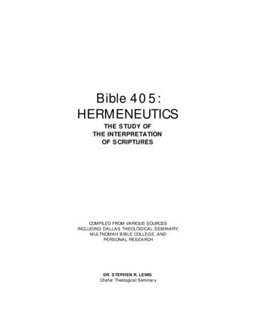
CE 405: Design of Steel Structures – Prof. Dr. A. VarmaTension Member DesignExample 3.3 Determine the effective net area and the corresponding design strength for thesingle angle tension member of Example 3.2. The tension member is an L 4 x 4 x 3/8 in. madefrom A36 steel. It is connected to a gusset plate with 5/8 in. diameter bolts, as shown in Figurebelow. The spacing between the bolts is 3 in. center-to-center.-Compare your results with those obtained for Example 3.2.axL 4 x 4 x 3/ 8d b 5/8 in.aL 4 x 4 x 3/ 8Gusset plate Gross area of angle Ag 2.86 in2 Net section area An (from Table 1-7 on page 1-36 of A
CE 405: Design of Steel Structures . See the AISC manual, section on specifications, Chapter D (page 16.1 –24) Facture of the net section will occur after the stress on the net section area reaches the ultimate stress Fu u e F A P f Therefore, nominal fracture strength Pn Ae Fu Where, Ae is the effective net area, which may be equal to the net area or smaller. The topic of .