Transcription
PRESSURE GAUGEINSTALLATION,OPERATION ANDMAINTENANCEI&M008-10098-5/02 (250-1353-L) Rev. 12/151
2
CONTENTSPageSelection and Application1.1Range . . . . . . . . . . . . . . . . . . . . . . . . . . . . . . . . . . . . . . . . . . . . . . . . . . . . . . . . . . . . . .41.2Temperature . . . . . . . . . . . . . . . . . . . . . . . . . . . . . . . . . . . . . . . . . . . . . . . . . . . . . . . . .41.3Media . . . . . . . . . . . . . . . . . . . . . . . . . . . . . . . . . . . . . . . . . . . . . . . . . . . . . . . . . . . . . . .41.4Oxidizing media . . . . . . . . . . . . . . . . . . . . . . . . . . . . . . . . . . . . . . . . . . . . . . . . . . . . . . .41.5Pulsation/Vibration . . . . . . . . . . . . . . . . . . . . . . . . . . . . . . . . . . . . . . . . . . . . . . . . . . . . .41.6Gauge fills . . . . . . . . . . . . . . . . . . . . . . . . . . . . . . . . . . . . . . . . . . . . . . . . . . . . . . . . . . .41.7Mounting . . . . . . . . . . . . . . . . . . . . . . . . . . . . . . . . . . . . . . . . . . . . . . . . . . . . . . . . . . . .42.0Temperature2.1Ambient Temperature . . . . . . . . . . . . . . . . . . . . . . . . . . . . . . . . . . . . . . . . . . . . . . . . . .42.2Accuracy . . . . . . . . . . . . . . . . . . . . . . . . . . . . . . . . . . . . . . . . . . . . . . . . . . . . . . . . . . . .42.3Steam service . . . . . . . . . . . . . . . . . . . . . . . . . . . . . . . . . . . . . . . . . . . . . . . . . . . . . . . .42.4Hot or very cold media . . . . . . . . . . . . . . . . . . . . . . . . . . . . . . . . . . . . . . . . . . . . . . . . .42.5Diaphragm seals . . . . . . . . . . . . . . . . . . . . . . . . . . . . . . . . . . . . . . . . . . . . . . . . . . . . . .52.6Autoclaving . . . . . . . . . . . . . . . . . . . . . . . . . . . . . . . . . . . . . . . . . . . . . . . . . . . . . . . . . .53.0Installation3.1Installation Location . . . . . . . . . . . . . . . . . . . . . . . . . . . . . . . . . . . . . . . . . . . . . . . . . . . .53.2Gauge reuse . . . . . . . . . . . . . . . . . . . . . . . . . . . . . . . . . . . . . . . . . . . . . . . . . . . . . . . . .53.3Tightening of gauge . . . . . . . . . . . . . . . . . . . . . . . . . . . . . . . . . . . . . . . . . . . . . . . . . . .53.4Process isolation . . . . . . . . . . . . . . . . . . . . . . . . . . . . . . . . . . . . . . . . . . . . . . . . . . . . . .53.5Surface mounting . . . . . . . . . . . . . . . . . . . . . . . . . . . . . . . . . . . . . . . . . . . . . . . . . . . . .53.6Flush mounting . . . . . . . . . . . . . . . . . . . . . . . . . . . . . . . . . . . . . . . . . . . . . . . . . . . . . . .54.0Operation4.1Frequency of inspection . . . . . . . . . . . . . . . . . . . . . . . . . . . . . . . . . . . . . . . . . . . . . . . .54.2In-service inspection . . . . . . . . . . . . . . . . . . . . . . . . . . . . . . . . . . . . . . . . . . . . . . . . . . .54.3When to check accuracy . . . . . . . . . . . . . . . . . . . . . . . . . . . . . . . . . . . . . . . . . . . . . . . .54.4When to recalibrate . . . . . . . . . . . . . . . . . . . . . . . . . . . . . . . . . . . . . . . . . . . . . . . . . . . .54.5Other considerations . . . . . . . . . . . . . . . . . . . . . . . . . . . . . . . . . . . . . . . . . . . . . . . . . . .54.6Spare parts . . . . . . . . . . . . . . . . . . . . . . . . . . . . . . . . . . . . . . . . . . . . . . . . . . . . . . . . . .55.0Gauge Replacement . . . . . . . . . . . . . . . . . . . . . . . . . . . . . . . . . . . . . . . . . . . . . . . . . . . . . . . . .56.0Accuracy: Procedures/Definitions . . . . . . . . . . . . . . . . . . . . . . . . . . . . . . . . . . . . . . . . . . . . . .66.1Calibration - Rotary movement gauges . . . . . . . . . . . . . . . . . . . . . . . . . . . . . . . . . . . .77.0Diaphragm Seals7.1General . . . . . . . . . . . . . . . . . . . . . . . . . . . . . . . . . . . . . . . . . . . . . . . . . . . . . . . . . . . . .87.2Installation . . . . . . . . . . . . . . . . . . . . . . . . . . . . . . . . . . . . . . . . . . . . . . . . . . . . . . . . . . .87.3Operation . . . . . . . . . . . . . . . . . . . . . . . . . . . . . . . . . . . . . . . . . . . . . . . . . . . . . . . . . . . .87.4Maintenance . . . . . . . . . . . . . . . . . . . . . . . . . . . . . . . . . . . . . . . . . . . . . . . . . . . . . . . . .87.5Failures . . . . . . . . . . . . . . . . . . . . . . . . . . . . . . . . . . . . . . . . . . . . . . . . . . . . . . . . . . . . .88.0Dampening Devices8.1General . . . . . . . . . . . . . . . . . . . . . . . . . . . . . . . . . . . . . . . . . . . . . . . . . . . . . . . . . . . . .88.2Throttle Screws & Plugs . . . . . . . . . . . . . . . . . . . . . . . . . . . . . . . . . . . . . . . . . . . . . . . .88.3Ashcroft Pulsation Dampener . . . . . . . . . . . . . . . . . . . . . . . . . . . . . . . . . . . . . . . . . . . .88.4Ashcroft Pressure Snubber . . . . . . . . . . . . . . . . . . . . . . . . . . . . . . . . . . . . . . . . . . . . . .88.5Ashcroft Needle Valves . . . . . . . . . . . . . . . . . . . . . . . . . . . . . . . . . . . . . . . . . . . . . . . . .88.6Chemiquip Pressure Limiting Valves . . . . . . . . . . . . . . . . . . . . . . . . . . . . . . . . . . . . . .89.0Test Equipment & Tool Kits9.1Pressure Instrument Testing Equipment . . . . . . . . . . . . . . . . . . . . . . . . . . . . . . . . . . . .99.2Tools & Tool Kits . . . . . . . . . . . . . . . . . . . . . . . . . . . . . . . . . . . . . . . . . . . . . . . . . . . . . .99.3Kits to Convert a Dry Gauge to a Liquid Filled or . . . . . . . . . . . . . . . . . . . . . . . . . . . . . .Weather Proof Case Gauge . . . . . . . . . . . . . . . . . . . . . . . . . . . . . . . . . . . . . . . . . . . . .99.421 2 & 31 2 1009 Duralife Gauge Tools . . . . . . . . . . . . . . . . . . . . . . . . . . . . . . . . . .10AppendixType 1188 Bellows Gauge Calibration Procedure . . . . . . . . . . . . . . . . . . . . . . . . . . . . . . . . . .11Type 1009 Calibration Procedure (Vacuum-Previous Style) . . . . . . . . . . . . . . . . . . . . . . . . . . .12Type 1009 Calibration Procedure (Pressure-Previous Style) . . . . . . . . . . . . . . . . . . . . . . . . . .13Type 1009 Calibration Procedure (Pressure & Vacuum-Current Style) . . . . . . . . . . . . . . . . . .14Type 1279 & 1379 I&M Liquid Fill Conversion Instruction . . . . . . . . . . . . . . . . . . . . . . . . . .15-16Type 1082 Calibration Procedure . . . . . . . . . . . . . . . . . . . . . . . . . . . . . . . . . . . . . . . . . . . .17-181.0Cover photo courtesy of Johnson/Yokogawa Co.Chemiquip is a registered trademark of Chemiquip Products Co. Inc.3
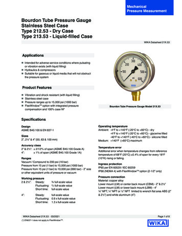
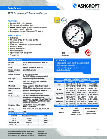
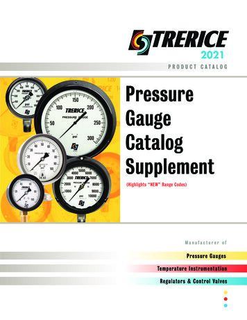
Glycerin satisfies most applications. While being the leastexpensive fill, its usable temperature range is 20/180 F.Silicone filled gauges have a broader service range: –40/250 F. Oxidizing media require the use of Halocarbon,with a service range of –40/250 F. Pointer motion will beslowed at the low end of the low end of these temperatureranges.1.7 Mounting – Users should predetermine how the gaugewill be mounted in service: stem (pipe), wall (surface) or panel(flush). Ashcroft wall or panel mounting kits should be orderedwith the gauge. See Section 3.1.0 SELECTION & APPLICATIONUsers should become familiar with ASME B40.100 (Gauges– Pressure Indicating Dial Type – Elastic Element) beforespecifying pressure measuring gauges. That document –containing valuable information regarding gauge construction,accuracy, safety, selection and testing – may be ordered from:ASME InternationalThree Park AvenueNew York, N.Y. 10016-5990800-843-2763 (US/Canada)001-800-843-2763 (Mexico)973-882-1170 outside North Americaemail: infocentral@asme.orgwww.asme.org2.0 TEMPERATURE2.1 Ambient Temperature – To ensure long life and accuracy, pressure gauges should preferably be used at an ambient temperature between –20 and 150 F (–30 to 65 C).At very low temperatures, standard gauges may exhibit slowpointer response. Above 150 F, the accuracy will be affectedby approximately 1.5% per 100 F. Other than discoloration ofthe dial and hardening of the gasketing and degradation ofaccuracy, non-liquid filled Type 1279 (phenolic case) and1379 (aluminum case) Duragauge gauge, with standardglass windows, can withstand continuous operating temperatures up to 250 F. Unigauge models 21 2 and 31 2 1009 and1008S liquid filled gauges can withstand 200 F but glycerinfill and the acrylic window of Duragauge gauges will tend toyellow. Silicone fill will have much less tendency to yellow.Low pressure, liquid filled Types 1008 and 1009 gauges mayhave some downscale errors caused by liquid fill expansion.This can be alleviated by venting the gauge at the top plug(pullout the blue plug insert). To do this the gauge must beinstalled in the vertical position.Although the gauge may be destroyed and calibration lost,gauges can withstand short times at the following temperatures: gauges with all welded pressure boundary joints, 750 F(400 C); gauges with silver brazed joints, 450 F (232 C) andgauges with soft soldered joints, 250 F (121 C). For expectedlong term service below –20 F (–30 C) Duragauge and 41 2 1009 gauges should be hermetically sealed and speciallylubricated; add “H” to the product code for hermetic sealing.Add variation XVY for special lubricant. Standard Duralife gauges may be used to –50 F (–45 C) without modification.2.2 Accuracy – Heat and cold affect accuracy of indication.A general rule of thumb for dry gauges is 0.5% of full scalechange for every 40 F change from 75 F. Double that allowance for gauges with hermetically sealed or liquid filledcases, except for Duragauge gauges where no extraallowance is required due to the elastomeric, compensatingback. Above 250 F there may exist very significant errors inindication.2.3 Steam service – In order to prevent live steam fromentering the Bourdon tube, a siphon filled with water shouldbe installed between the gauge and the process line.Siphons can be supplied with ratings up to 4,000 psi. Iffreezing of the condensate in the loop of the siphon is a possibility, a diaphragm seal should be used to isolate thegauge from the process steam. Siphons should also be usedwhenever condensing, hot vapors (not just steam) are present. Super heated steam should have enough piping orcapillary line ahead of the siphon to maintain liquid water inthe siphon loop.2.4 Hot or very cold media – A five foot capillary line assembly will bring most hot or cold process media within the recommended gauge ambient temperature range. For media aboveWARNING: To prevent misapplication, pressure gaugesshould be selected considering media and ambient operatingconditions. Improper application can be detrimental to thegauge, causing failure and possible personal injury, propertydamage or death. The information contained in this manual isoffered as a guide in making the proper selection of a pressuregauge. Additional information is available from Ashcroft Inc.The following is a highlight of some of the more important considerations:1.1 Range – The range of the instrument should be approximately twice the maximum operating pressure. Too low arange may result in (a) low fatigue life of the elastic elementdue to high operating stress and (b) susceptibility to overpressure set due to pressure transients that exceed the normal operating pressure. Too high a range may yield insufficient resolution for the application.1.2 Temperature – Refer to Section 2 of this manual forimportant information concerning temperature related limitations of pressure gauges, both dry and liquid filled.1.3 Media – The material of the process sensing element mustbe compatible with the process media. Use of a diaphragm sealwith the gauge is recommended for process media that (a) iscorrosive to the process sensing element; (b) contain heavyparticulates (slurries) or (c) are very viscous including thosethat harden at room temperature.1.4 Oxidizing media – Gauges for direct use on oxidizingmedia should be specially cleaned. Gauges for oxygen service should be ordered to variation X6B and will carry theASME required dial marking “USE NO OIL” in red letters.Gauges for direct use on other oxidizing media may beordered to variation X6W. They will be cleaned but carry nodial marking. PLUS! Performance gauges or Halocarbonfilled gauge or diaphragm fill is required for use with oxidizing media; order variation XCF.1.5 Pulsation/Vibration – Pressure pulsation can be dampened by several mechanisms; the patented PLUS! Performance gauge will handle the vast majority of applications.One exception to this is high frequency pulsation which isdifficult to detect. The only indication may be an upscale zeroshift due to movement wear. These applications should beaddressed with a liquid filled gauge, or in extreme cases, aremotely mounted liquid filled gauge connected with a lengthof capillary line. The small diameter of the capillary providesexcellent dampening, but can be plugged. The Ashcroft 1106pulsation dampener and 1112 snubber are auxiliary deviceswhich dampen pulsation with less tendency to plug.1.6 Gauge fills. – Once it has been determined that a liquidfilled gauge is in order, the next step is selecting the type of fill.4
750 F (400 C) the customers should use their own smalldiameter piping to avoid possible corrosion of the stainless steel.The five foot capillary will protect the gauges used on the common cryogenic (less than –300 F (200 C) gases, liquid argon,nitrogen, and oxygen.) The capillary and gauge must becleaned for oxygen service. The media must not be corrosive tostainless steel, and must not plug the small bore of the capillary.2.5 Diaphragm seals – A diaphragm seal should be used toprotect gauges from corrosive media, or media that will plugthe instrument. Diaphragm seals are offered in a wide varietyof designs and corrosion resistant materials to accommodate almost any application and most connections. Visitwww.ashcroft.com for details.2.6 Autoclaving – Sanitary gauges with clamp
Users should become familiar with ASME B40.100 (Gauges – Pressure Indicating Dial Type – Elastic Element) before specifying pressure measuring gauges. That document – containing valuable information regarding gauge construction, accuracy, safety, selection and testing – may be ordered from : ASME International Three Park Avenue