Transcription
Operating instruction manual OI/PS35-EN Rev. DPS35Magnetic Level Gauge SwitchMagnetically actuated pneumaticswitchK-TEK ProductsIntroductionThis operation and instruction manual provides the followinginformation:– – Operation - see page 3– – Mounting and installation - see pages 3-4– – Maintenance - see page 4– – Troubleshooting - see page 4– – LR35 Latching Relay - see page 5
Table of Contents1.0 Description.32.0 Application.33.0 Operation.34.0 Mounting & Installation. 3-45.0 Maintenance.46.0 Troubleshooting.47.0 LR35 Latching Relay.57.1 Description of Operation.57.2 Mounting / Installation.67.3 LR35 Versa Valve Mounting Plate .78.0 Warranty Statement.89.0 RMA Form.92 PS35 Magnetic Level Gauge Switch Operating instruction manual
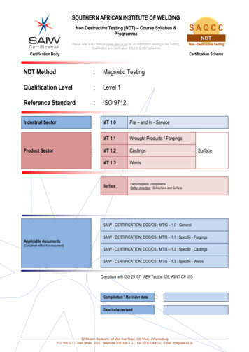
1.0 DescriptionThe ABB PS35 is a point level (on - off) pneumatic switch device used in conjunction with the KM26 Magnetic LevelGauge. LS Series Cage Level switch or an External Chamber containing a magnetic ABB float. The unique magneticcoupling action eliminates the need for such things as seals, diaphragms, springs or torque tubes. Since process connections to the switch are eliminated, the user is insured complete isolation from the process. Valves are not requiredto block off the switch from the process for maintenance or operational testing. Preventive maintenance functions aregreatly reduced since the switch never contacts the process fluid.2.0 ApplicationThe PS35 is designed to provide a pneumatic control signal dependent on the liquid level within a vessel. The deviceis configurable such that actuation can occur on rising and falling level. When a magnetic float passes in the first direction, the PS35 will route the input supply gas through to its output port. When the float passes in the opposite direction,the supply gas is shut off (disconnected) from the output port and the output port typically vented to the atmosphere.The PS35 thus provides the user with a pneumatic signal that can be used to activate alarms and/or open and closecontrol valves. An example application would be the pneumatic operation of safety shutdown systems on oil and gasproduction equipment.3.0 OperationThe PS35 switch mechanism consists of the following integral components:1. Actuating lever-spindle-magnet assembly2. Whisker valve assembly3. Pneumatic relayWhen the whisker valve is in the unactuated position (seeFigure 1), a backpressure is created that causes the pneumatic relay diaphragm to move. This allows supply gas atthe relay input port to pass through to the output port andthus to the final control element. As the magnetic floattravels past the switch, the actuating level tips the whiskerlevel, venting the backpressure on the relay. This allowsthe relay diaphragm to vent to atmosphere and move tothe opposite position. The supply pressure is then blockedfrom the output port, and the output port is vented to atmosphere. The PS35 is easily reconfigured in the field withregard to the action of the air-on/air-off relative to the float.Figure 14.0 Mounting & InstallationThe simplicity of mounting the PS35 switch housing is such that the only necessary tool is a small screwdriver. Theswitch is attached to the KM26 via two small stainless steel variable clamps. These clamps allow the switch to be positioned anywhere over the entire length of the float chamber, thereby providing an infinitely variable trip point setting.Loosening the clamps will allow the PS35 to be easily moved to provide a new trip point. Other switches can be addedat any time without the concern for additional process piping or valves. The optional LR35 (Latching Relay) housingcan also be attached to the KM26 MLG chamber and two small stainless steel variable clamps.Note: Two switches can be mounted so they can trip at the same point or at two different points separated by lessthan the length of a switchOperating instruction manual PS35 Magnetic Level Gauge Switch 3
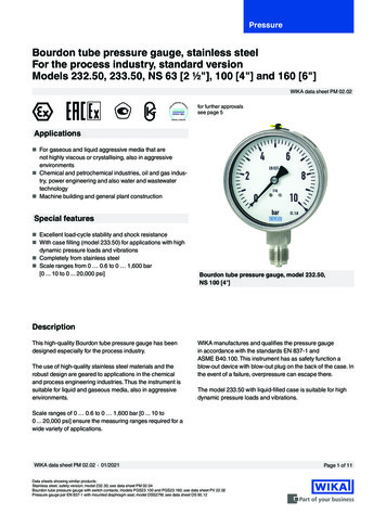
Example Configurations:PS35PS35 (Hi Level Switch)PS35 (Lo Level Switch)KM26 MLGPS35 Mounted on KM26 Magnetic Level GaugeLS700 (LSSeries)PS35 Mounted on LS SeriesMechanical Level Switch5.0 MaintenanceThe PS35 does not require any routine maintenance in normal day to day operation if a clean, dry air supply is provided.6.0 TroubleshootingThe PS35 switch is a very reliable device if a clean, dry air or gas supply is provided. If you suspect the switch is notworking, check the following:1. Supply pressure is between 15 and 100 psi (1 and 7 bars).2. Check the operation of the pneumatic relay by removing the cover and pinching the tube connecting form thepneumatic relay to the whisker valve assembly. The relay should connect the supply port to the output port whenthe tube is pinched.3. Verify that the magnet is correctly oriented. See “proper magnet-spindle orientation” detail in section 7.0 on page 5.4. Move the float back and forth past the switch and see if the switch will change positions. It should make an audibleclick as it snaps from one position to the other. If the switch does not change position there are there possibleproblems.a. The spindle ahs some restrictions that are binding it. Check by manually moving the spindle and look forthe following two things:1.) Tubing interfering with magnet or spindle2.) Foreign material in pivot point.b. The switch is positioned too far away from the float. See section 4.0 Mounting and Installation on page 3.Remove the switch from the chamber and pass a float by it. The switch should work if the checks in step“A” work. Position the switch as close to the indicatory as possible.c. If the buoyancy of the float is too small to overcome the magnetic pull of the switch. The probable cause forthis condition is that the specific gravity of the fluid has fallen at least 5% below the specified specific gravity. To check for this condition, the chamber will have to be slowly filled with the process liquid. When thefloat as shown by the external indicator reaches the vicinity of the switch it will stop moving even thoughmore fluid is continually added. The best way to correct this problem is to replace the float with a float thatmatches the specific gravity of the fluid.5. Remove the output port fitting and either move the float back and forth past the switch or move the spindle manually and observe if the air is turned on and off at the output port. If not, check the whisker valve to see if it is pluggedor if the tubing from the whisker valve to the pneumatic is crimped. To get to the whisker valve remove the twoscrews that hold the core of the switch to the side of the enclosure.4 PS35 Magnetic Level Gauge Switch Operating instruction manual
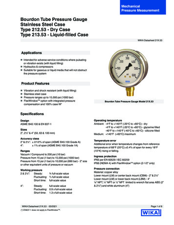
7.0 LR35 Latching RelayLR35 Latching Relay is used in conjunction with PS35 switches for differential gap control (See Figure 2). The partnumber is VPP-3301-316.Description: PS35/H triggers LR35 to provide supply pressure to control valve. Supply pressureat control valve will be maintained until float drops below PS35/L. Which subsequently ventsactuatorpressure to-atmosphere.DESCRIPTIONPS-35/ H TRIGGERS LR-35 TO PROVIDE SUPPLY PRESSUREFilterPS35/HTO CONTROL VALVE. SUPPLY PRESSURE AT CONTROL VALVE WILL BEMAINTAINED UNTIL FLOAT DROPS BELOW PS-35/ L. WHICH SUBSEQUENTLYVENTS ACTUATOR PRESSURE TO ATMOSPHERE.f il t ersuppl yUpperPilotSupplyUPPER NInFilterPS35/LLOWER PILOTLowerPilotf il t erFigure 27.1 Description of Operation1. Applying pressure to the upper pilot connects the main air pressure at the “In” port to port “A” (approximately 10 psig is required to activate).2. Main air pressure is maintained at port “A” even when the pressure at the upper pilot is removed.3. Applying pressure to the lower pilot connects port “A” to the exhaust port.NOTE:1. The LR35 is designed to be sued with 2 PS35 switches to control fill/drain valves or pumps to controllevel when an adjustable differential is desired.2. Pilot ports are 1/8” FNPT.3. “A”, “In” and “Exhaust Ports” are 1/4” FNPT.4. Materials of construction are 316L SS.Operating instruction manual PS35 Magnetic Level Gauge Switch 5
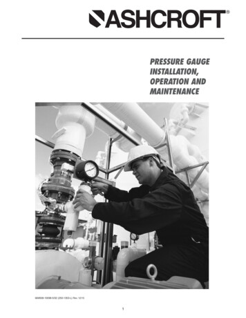
7.2 Mounting / InstallationPS35PS35LR356 PS35 Magnetic Level Gauge Switch Operating instruction manual
7.3 LR35 Versa Valve Mounting PlateOperating instruction manual PS35 Magnetic Level Gauge Switch 7
8.0 Warranty Statement5 YEAR WARRANTY FOR:KM26 Magnetic Liquid Level Gauges; MagWave Dual Chamber System; LS Series Mechanical Level Switches (LS500, LS550,LS600, LS700, LS800 & LS900); EC External Chambers, STW Stilling Wells and ST95 Seal Pots.3 YEAR WARRANTY FOR:KCAP300 & KCAP400 capacitance switches.2 YEAR WARRANTY FOR:AT100, AT100S and AT200 series transmitters; RS80 and RS85 liquid vibrating fork switches; RLT100 and RLT200 reed switchlevel transmitters; TX, TS, TQ, IX and IM thermal dispersion switches; IR10 and PP10 External Relays; MT2000, MT5000,MT5100 and MT5200 radar level transmitters; RI100 Repeat Indicators; KP paddle switches; A02, A75 & A77 RF capacitancelevel switches and A38 RF capacitance level transmitters; Buoyancy Level Switches (MS50, MS10, MS8D & MS8F); MagneticLevel Switches (MS30, MS40, MS41, PS35 & PS45).1 YEAR WARRANTY FOR:KM50 gauging device; AT500 and AT600 series transmitters; LaserMeter and SureShot series laser transmitters; LPM200 digitalindicator; DPM100 digital indicators; APM100 analog indicators; KVIEW series digital indicators and controllers; SF50 and SF60vibrating fork switches, KB Electro-Mechanical Continuous Measuring Devices, KSONIK ultrasonic level switches, transmitters &transducers, ChuteMaster Microwave Transmitter / Receiver and TiltMaster Switches.SPECIAL WARRANTY CONSIDERATIONS:ABB does not honor OEM warranties for items not manufactured by ABB (i.e. Palm Pilots). These claims should be handleddirectly with the OEM.ABB will repair or replace, at ABB’s election, defective items which are returned to ABB by the original purchaser within the periodspecified above from the shipment date of the item and which is found, upon examination by ABB, to its satisfaction, to containdefects in materials or workmanship which arose only under normal use and service and which were not the result of either alterations, misuse, abuse, improper or inadequate adjustments, applications or servicing of the product. ABB’s warranty does notinclude onsite repair or services. Field service rates can be supplied on request.If a product is believed to be defective, the original purchaser shall notify ABB and request a Returned Material Authorizationbefore returning the material to ABB, with transportation prepaid by the purchaser. (To expedite all returns/repairs from outsideof the United States, consult ABB’s customer service team (service@ktekcorp.com) to determine an optimal solution for shippingmethod and turnaround time.) The product, with repaired or replaced parts, shall be returned to the purchaser at any point in theworld with transportation prepaid by ABB for best-way transportation only. ABB is not responsible for expedited shipping charges.If the product is shipped to ABB freight collect, then it will be returned to the customer freight collect.If inspection by ABB does not disclose any defects in material or workmanship, ABB’s normal charges for repair and shipmentshall apply (minimum 250.00 USD).The materials of construction for all ABB products are clearly specified and it is the responsibility of the purchaser to determinethe compatibility of the materials for the application.THE FOREGOING WARRANTY IS ABB’S SOLE WARRANTY AND ALL OTHER WARRANTIES EXPRESSED, IMPLIED, ORSTATUTORY, INCLUDING ANY IMPLIED WARRANTY OF MERCHANTABILITY OF FITNESS FOR A PARTICULAR PURPOSE,ARE EXCLUDED AND NEGATED TO THE MAXIMUM EXTENT PERMITTED BY LAW. NO PERSON OR REPRESENTATIVE ISAUTHORIZED TO EXTEND ANY OTHER WARRANTY OR CREATE FOR ABB ANY OTHER LIABILITY IN CONNECTION WITHTHE SALE OF ABB’S PRODUCTS. THE REMEDIES SET FORTH IN THIS WARRANTY ARE EXCLUSIVE OF ALL OTHERREMEDIES AGAINST ABB. ABB SHALL NOT BE LIABLE FOR ANY CONSEQUENTIAL, INCIDENTAL, OR SPECIAL DAMAGES OF ANY KIND. ABB’S SOLE OBLIGATION SHALL BE TO REPAIR OR REPLA
The ABB PS35 is a point level (on - off) pneumatic switch device used in conjunction with the KM26 Magnetic Level Gauge. LS Series Cage Level switch or an External Chamber containing a magnetic ABB float. The unique magnetic coupling action eliminates the need for such things as seals, diaphragms, springs or torque tubes. Since process con-nections to the switch are eliminated, the user is .