Transcription
Installationand Operation ManuallIncludes Installation,Operation, Serviceand ReplacementParts InformationThroughout this manual,statements indicatingprecautions necessary toavoid equipment failure arereferenced in a Note. Statementsindicating potential hazards thatcould result in personal injury orproperty damage are referencedin a Caution! box.TD486 Dust CollectorsThis manual is the property of the owner. Leave with the unit when set-up andstart-up are complete. Donaldson Company reserves the right to change designand specifications without prior notice.IOM 7470101Revision 5
Donaldson Company, Inc.CAUTION!Application of Dust Control Equipment2 Combustible materials such as buffing lint, paper, wood, aluminum or steel dust, weld fume, orflammable solvents represent fire or explosion hazards. Use special care when selecting and operating all dust or fume collection equipment when combustible materials are present to protectworkers and property from damage due to fire and/or explosion. Consult and comply withNational and Local Codes relating to fire or explosion and all other appropriate codes whendetermining the location and operation of dust or fume collection equipment. When combustible materials are present, consult with an installer of fire extinguishing systemsfamiliar with these types of fire hazards and local fire codes for recommendations and installationof fire extinguishing and explosion protection systems. Donaldson dust collection equipment isnot equipped with fire extinguishing or explosion protection systems. DO NOT allow sparks, cigarettes or other burning objects to enter the hood or duct of any dustor fume control equipment as these may initiate a fire or explosion. For optimum collector performance, use only Donaldson replacement parts.
TD486 Dust CollectorsTable of ContentsIntroduction . . . . . . . . . . . . . . . . . . . . . . . . . . . .5Operational Explanation . . . . . . . . . . . . . .5Hoppers . . . . . . . . . . . . . . . . . . . . . . . . . . .6Installation . . . . . . . . . . . . . . . . . . . . . . . . . . . . .6Inspection . . . . . . . . . . . . . . . . . . . . . . . . . .6Pre-Installation . . . . . . . . . . . . . . . . . . . . . .6Assembly of Standard Equipment . . . . . . . .6Blower Assembly . . . . . . . . . . . . . . . . . . . .7Inlet . . . . . . . . . . . . . . . . . . . . . . . . . . . . . .7Inlet Duct . . . . . . . . . . . . . . . . . . . . . . . . . .7Electrical Installation . . . . . . . . . . . . . . . . . . . . . .9TD Solid-State Timer Specs . . . . . . . . . . . .9TD Solid-State Timer Installation . . . . . . . .9Air Supply Installation . . . . . . . . . . . . . . .11Pre Start-up Check . . . . . . . . . . . . . . . . . . . . . .11Service . . . . . . . . . . . . . . . . . . . . . . . . . . . . . . . .12Element Replacement . . . . . . . . . . . . . . . .12Replacement Parts . . . . . . . . . . . . . . . . . . . . . . .14Parts Drawing 1, Cabinet Assembly . . . . . . . . .14Parts Drawing 2, Magnehelic Pack . . . . . . . . . .18Parts Drawing 3, Control Box Pack . . . . . . . . .20Parts Drawing 4, Manual Pulse Control . . . . . .22Parts Drawing 5, Control Box Pack, NEMA 9 .24Parts Drawing 6, Photohelic Pack . . . . . . . . . . .26Parts Drawing 7, 5-Gallon Leg Pack . . . . . . . . .27Parts Drawing 8, Weather Cover . . . . . . . . . . . .28Parts Drawing 9, 5-Gallon Pail Pack . . . . . . . . .29Parts Drawing 10, Explosion Vent Pack . . . . . .30Parts Drawing 11, Hose Drum . . . . . . . . . . . . .31Parts Drawing 12, 55-Gallon Drum Pack . . . . .32Parts Drawing 13, Delta P Control . . . . . . . . . .33Limited Warranty . . . . . . . . . . . . . . . . . . . . . . .36This manual contains specific precautionarystatements relative to worker safety. Readthoroughly and comply as directed. Discussthe use and application of this equipmentwith a Donaldson representative. Instructall personnel on safe use andmaintenance procedures.Data SheetModel NumberSerial NumberShip DateInstallation DateCustomer NameAddressFilter TypeAccessoriesOther3
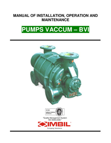
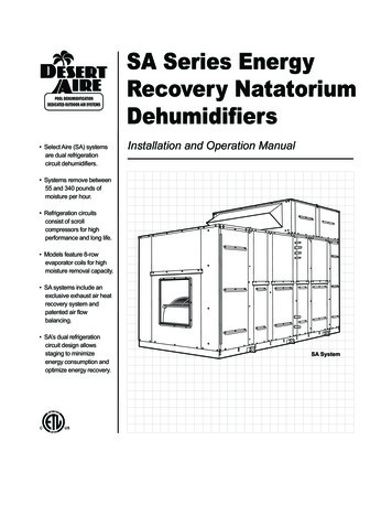
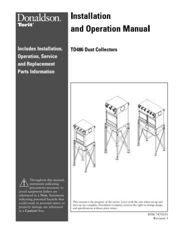
Donaldson Company, Inc.blowpipesNote: The Model TD486 DustCollector is used for illustrativepurposes throughout this manual.Part numbers and quantitydifferences for all models are shownon the parts list.tube plate1" NPT airmanifold inlet*Magnehelic Gaugeventurisair valveselementsdoorcabinethoppercontaminatedair inlethopper outlet* Optional - not included with dust collector.Note: Sprinkler taps are not shown.Figure 1, Cutaway View4
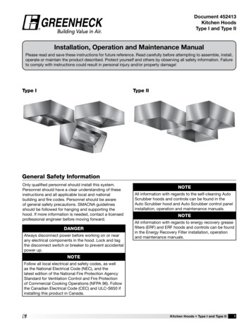
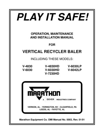
TD486 Dust CollectorsIntroductionThe Torit TD Dust Collector is used for collectionof airborne dust and particulate. Whether inanswer to the problems of air pollution or as apart of a manufacturing operation, Torit TDs provide continuous operation.Operational Explanation (See Figure 2)Normal OperationDuring normal operation, dust enters the inlet andis collected on the outside of the elements. The filtered air passes up through the venturis andplenum and out the blower outlet or outlet collar.Noise LevelA certain level of noise is created with any airmoving device. If for any reason this noise level isabove a tolerable level, exhaust silencers are available from Donaldson Torit as optional equipment.Contact your Donaldson Torit representative foroptional accessory blowers, attenuators, filter elements.Normal OperationFilter CleaningFilter element groups are cleaned automaticallyand alternately. The result is that at any one timeonly one group of elements is taken off stream forcleaning, while the remaining elements are still inoperation. Elements are: 7-7/8 O.D., 3-9/16” I.D.,by 16” long.During filter element purge, the solid-state controltimer automatically selects the elements to becleaned and energizes the air valve solenoid. Theair valve opens, sending a pulse of compressed airinto the blowpipe and down through the venturis.The compressed air pulse and induced air passthrough the filter elements from the inside outward, removing the dust from the outside of theelements. The dust falls into the hopper. At the endof the 100 millisecond pulse, the air valve closesand the elements are back in operation.Element Purgeblowpipeplenumventuriinduced airelementsair pulseFigure 2, Operational Schematics5
Donaldson Company, Inc.HoppersAssembly of Standard EquipmentStandard hoppers are at least 59 as viewed from ahorizontal reference and have one inlet.Note: A crane is recommended for the unloading,assembly, and installation of the dust collector.Hopper discharge clearance on standard hoppers is48”. Other hopper clearances are available on special order—for information on optional clearances,contact your local Donaldson Torit Products representative.InstallationCAUTION! Connect the lifting sling to a minimum of four (4) cabinet lifting lugs. Distribute loads evenly. Connect the lifting sling to doublethickness cabinet lifting lugs whenpossible. Use clevices, not hooks, on the liftingsling. Use spreader bars on the lifting sling.InspectionThe TD dust collector is normally shipped by common carrier truck and should be checked for anydamage that may have occurred en route. Anydamage should be noted and the carrier notifiedimmediately.Pre-Installation (See Figure 1)The weight of the dust collector and all auxiliaryequipment must be considered when planning forthe foundation. See individual SpecificationControl Drawing for dust collector weight.See Specification Control Drawing for anchor boltlocation. The 3/8” anchor bolts must extend1-3/4” above foundation. The collector locationshould be determined with consideration for emptying the hopper, shortest run for the location ofduct work, electrical and air connections andmaintenance. In the case of hazardous dust, consult with local authorities for the location of theunit.Remove all crating and strapping from the unit.All parts, bolts, nuts, etc. are shipped inside of theunit. Remove before lifting unit off the pallet.6Note: Each item to be attached to your collector isaccompanied by a drawing that shows the attachment. Refer to both the drawings and this manualwhen erecting your collector.Hopper to cabinet assembly is done on the job site.Remove hopper from pallet and stand on hopperdischarge opening. Apply 1/4” diameter sealer tothe hopper flange (see Parts Drawing 1 CabinetAssembly) NOTE: Apply sealer inside bolt holes.Lift cabinet from pallet and position on top ofhopper.
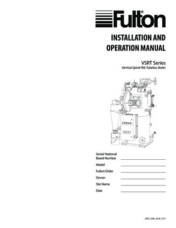
TD486 Dust CollectorsBolt hopper to cabinet with 3/8-16 x 1-1/4” Grade2 bolts, flat washers, lock washers, and nuts. Liftcabinet and hopper assembly and attach legs andcross bracing with 3/8-16 x 1-1/4” Grade 2 bolts,flat washers, lock washers, and nuts. Note that legand cross bracing bolting requires two flat washersper bolt. DO NOT tighten bolts. Position unit onpermanent mounting platform and bolt in place.TIGHTEN ALL LEG AND Cross bracing BOLTS.Blower Assembly (must be purchased separately)InletsInlets are welded to hoppers and require customerto specify proper inlet size and location with eachunit.Inlet Duct (must be purchased separately)Inlet duct work must be of proper size to handleair volume required at recommended velocity fordust to be conveyed to the collector.With a Donaldson Torit supplied blower:When installing duct work, use the shortest possible runs and large radius elbows. Seal all joints. Mount blower on pre-cut outlet in cabinet roof.Connect inlet duct to inlet on hopper. See also blower installation instructions supplied with blower.If you supply your own blower, check withDonaldson torit for cabinet pressure limitationsbefore ordering blower.When installing a remote blower, connect ductwork to the roof panel outlet. Factory-availableoutlets measure 6”-12” in diameter (1” increments).ONInput Power OFFOutput No. 1 ONOFFONOutput No. 2OFFON TIME for all outputs(See Specifications)OFF TIME between any two pulses(See Specifications)Output No. N ONOFF*N (3) for TD486Figure 3, Operating Logic Diagram7
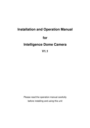
Donaldson Company, Inc.*Blower with DamperLifting LugAir Valve*Magnehelic GaugeAir Manifold*Solid State TimerDoor*Air Supply Line*Blower ElectricalConnection*Solenoid ElectricalConnection*Air Inlet Duct*Air Filter(Bleed Type)*Air Valve*Air SupplyLine*Power SupplyDisconnect Switch*Incoming Power Supply230-460/60/3*Air Regulator*Low Voltage (120 VAC)Magnetic StarterFigure 4, Typical Installation8
TD486 Dust CollectorsElectrical InstallationCAUTION!Disconnect electrical power beforeservicing any electrical component.2. Input: 105-135 VAC, 50-60 Hz.3. Output: Type—solid state switch (triac). Theload is carried by and turned on and off by thetriac. Rating—200 watts maximum load peroutput.4. Pulse Width: Factory-set at 100 milliseconds.Note: All electrical work must be done by a qualified electrician according to local codes.Continuous duty TD—standard TD units areequipped with 120 VAC solenoid valves rated at14.6 watts each, and a solid-state electronic120/60/1 control timer.Note: Solid-state TD control requires a low voltage(120 V) control circuit in fan circuit to be suppliedby others.TD Solid-State Timer Specifications (AutomaticCleaning Only)1. Operating Logic: Input power is applied to L1and L2 of the timer control circuit board whichis in parallel with the low voltage (120/60/1)coil of the fan magnetic starter. Upon fan startup, power is supplied to the control board andthe preset OFF time is initiated. At the end ofthe OFF time, the control will energize a solenoid to provide the cleaning pulse for one segment of the filter elements and then step to thenext segment. This cycle is continuous unless anauxiliary control, such as a pressure switch, isused to control the timer. See Figure 3,Operating Logic Diagram.5. Off Time: Adjustable between ranges shown. 1to 1.5 seconds minimum, 60 to 66 secondsmaximum (factory set).6. Operating Temperature Range: -20 to 130 F.7. Transient Voltage Protection: 50 KW transientfor 20µs duration once every two seconds.TD Solid-State Timer Installation InstructionsNote: All electrical work must be done by a qualified electrician according to local codes.1. Install proper sized starter (with low voltagecontrol circuit) conduit and wires for fan motor.2. Using wiring diagram (Figure 5 Wiring Diagramand inside control timer cover), make properconnections to fan motor, fan motor starter,solid state timer, and solenoid valves.Note: In grounded systems, neutral to control boxmust be connected to L2 of the control terminalboard.9
Donaldson Company, Inc.3. Bump the fan motor and check for proper rotation by referencing the rotation sticker locatedon the motor mounting plate. To prevent possible eye injury, wait for the wheel to run downto a very slow speed and wear eye protection.Proper fan rotation is extremely important. Even ifthe fan is running in the wrong direction, it willdeliver approximately 40% of its rated air volume,but it will required more then its rated horsepower.If rotation is in the direction opposite the arrow,simply reverse any two leads (3 phase only) on theoutput of the fan motor starter.4. Check operation of the solenoid valves. Thesevalves should open and close continuously witha factory-set dwell between each pulse.Note: To reduce compressed air consumption, aPhotohelic * or similar device can be used, allowing valves to pulse only when pressure reaches setpoint.5. Caulk fittings through walls or roof.*Photohelic is a registered trademark of Dwyer Instruments, Inc.L1L2L31FU2FU3FUControl BoxFan StarterDisconnect1M 10.L 1T11T21T31L11L21L3230 V3ø60 1/4H1X1Stop230 VH2 H3Fan1 MTROff Time On TimePressure SwitchX2Start1 2 3Program LugTimingLogicH4115 VProgram PinsPowerSupply10.LControlLogic1M1M*ITGS4 FU 3 AmpL1 L2SOLCOM1 23105 to 135 VAC, 50-60 HzWiring by Others460 VH1 H3 H2 H4X1115 VX2Solenoid Valves* 1 TGS (by others) is optional and is used for downtime pulsing.Figure 5, Solid-State Timer Wiring Diagram10
TD486 Dust CollectorsAir Supply InstallationOperating AdjustmentsRemove pipe plug from the end of dust collectormanifold and connec
and Operation Manual TD486 Dust Collectors This manual is the property of the owner. Leave with the unit when set-up and start-up are complete. Donaldson Company reserves the right to change design and specifications without prior notice. Throughout this manual, statements indicating precautions necessary to avoid equipment failureare referenced in a Note. Statements indicating potential .