Transcription
Distribution of Timing: Basics and Sync overthe Physical LayerWSTS Tutorial – 24-25 March 2021Silvana Rodrigues Huawei – Stefano Ruffini, Ericsson
Giulio BottariContents— 1.General— 1.1 Time vs. Frequency— 1.2 Master-Slave vs. Plesiochronous— 1.3 Fundamental technologies and timing protocols— 2. Frequency Sync over the Physical Layer— 2.1 Introduction— 2.2 SyncE— 2.3 OTNCredits:- Figures in slides 5, 6, 9, 15 taken from book «Synchronous Ethernet andIEEE 1588 in Telecoms: Next Generation Synchronization Networks»(Wiley, 2013, ISBN: 978-1-848-21443-9)2020-10-28 Page 2
Giulio Bottari1. General2020-10-28 Page 3
Time vs FrequencyGiulio Bottari125MHz x PPMCounterNotSynchronizedCount125MHz y PPMCounterTime125MHz x 5MHz x PPMPLLCounterTime125MHz x PPMCounter125MHz x PPMPLLClear (1PPS)Counter1PPS 1 Pulse Per Second2020-10-28 Page 4Time/PhaseSynchronizedCountTime
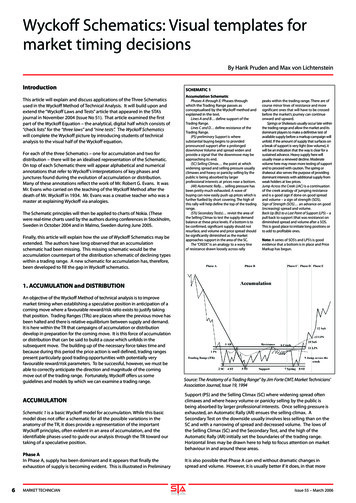
Master-Slave vs. PlesiochronousGiulio Bottari—Original focus is Frequency synchronization. Basic concepts in ITU-T G.810:— plesiochronous mode : A mode where the essential characteristic of time scales or signals such that theircorresponding significant instants occur at nominally the same rate, any variation in rate beingconstrained within specified limits— master slave mode : A mode where a designated master clock is used as a frequency standard which isdisseminated to all other clocks which are slaved to the master clock— mutually synchronized mode : A mode where all clocks exert a degree of control on each otherDistributed PRC—PRC originally mainly based on Cesium technology:— Timing Distribution based on Centralizedarchitectures (based on «Master-Slave»)— Increased use of GNSS-based sync leading to a mixof «Distributed PRC» and «Master-Slave»— Renewed interest on Mutually Synchronizedmode in the time sync domain2020-10-28 Page 5Master-SlavePRCPRCPRCSSUPRCPRC Primary Reference ClockSSU Synchronization Supply UnitSSUSSU
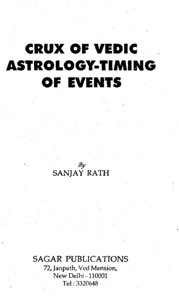
Basic Technologies:GNSS, Atomic clocks, PLLGiulio Bottari—Master-Slave mode enabled byPLL techniques—Sync Masters of the network :—GNSS Reveivers—Atomic Clocks (Cesium forfrequency accuracy betterthan 10-11)ui(t)Phase Detectorui(t) input reference timing signaluo(t) output reference timing signalupd(t) loop filter output signalulf(t) phase detector output signal2020-10-28 Page 6ulf(t)upd(t)Loop Filteruo(t)VCO
Timing Protocols—NTP, Network Time Protocol defined by IETF—protocol for clock synchronization between computer systems over packet-switchednetworks—RFC 1305 (NTP version 3) 1992—Latest version v4— RFC 5905: Network Time Protocol Version 4: Protocol and Algorithms Specification— RFC 5906: Network Time Protocol Version 4: Autokey Specification— RFC 5907: Definitions of Managed Objects for Network Time Protocol Version 4 (NTPv4)— RFC 5908: Network Time Protocol (NTP) Server Option for DHCPv6—PTP, Precision Timing Protocol, defined by IEEE 1588—V1 (2002)—V2 (2008)—V2.1 (2019)2020-10-28 Page 7Giulio Bottari
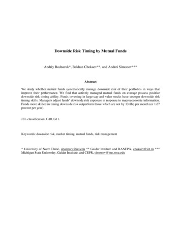
How NTP Works—T1 Originate Timestamp— Time request sent by clientClientServerT1 09:00:000—T2 Receive TimestampT2 09:00:005— Time request received by server—T3 Transmit TimestampT309:00:015— Time reply sent by server—T4 Destination TimestampT4 09:00:025— Time reply received by client—Round Trip Delay (T4-T1)-(T3-T2)— Round Trip Delay 25-10 15—Clock Offset [(T2-T1)-(T4-T3)]/2TimeCorrected time09:00:0225— Clock Offset [5-10]/2 -2.5(Clients actual time when reply received was therefore 09:00:0225)—Key Assumptions:— One way delay is half Round Trip (symmetry!)— Drift of client and server clocks are small and close to same value— Time is traceable2020-10-28 Page 8TimeGiulio Bottari
IEEE 1588-2008/2019Giulio Bottari—The Grandmaster “reference clock” sends a series of time-stamped messages to slaves.—Slaves process timestamps and synchronize to the Grandmaster.—Frequency can be recovered from an accurate time of day reference (but physical layer can alsobe used )Clock—Best Master Clock Algorithm to define the hierarchyreference—Accuracy is possible by means of:MasterSlave— Proper packet rate (up to 128 per second)— Hardware time-stamping(eliminate software processing delays)— Timing support in the network(e.g. transparent clocks, boundary clocks)BCSlaveMasterOCGMPassiveSlave clock—New features in 2019:— Addition of special ports to allow some technologies (e.g.WiFi and EPON) to use their inherent timing support— New optional features (e.g. cumulative rate ratio,performance monitoring)— High accuracy profile— Security options2020-10-28 Page 9TCMasterBCMasterSlavePTP messages over established PTP pathPTP control messages over valid network pathMaster
Timing SupportGiulio BottariTiming packets are terminated and regenerated by Node NTiming packetTiming packetSNM.SNMasterSlavee.g. IEEE1588 Boundary Clock, NTP Stratum ClockLatency (Residence Time) is calculated by NE and the information is added in the timing packetTiming packetTiming packetSMMaster.Residence TimeRTS.SNSlavee.g. IEEE1588 Transparent ClockTo remove (reduce) «Time Error» components internal to the nodes2020-10-28 Page 10
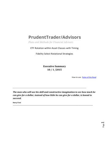
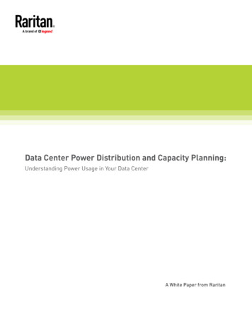
PTP Time Transfer TechniqueMaster clock portDelay Reqt4t2t3t 1, t 2Slave clock timeFollow UpTimestamps known byone-stepmaster clockSynct1Master clock timeSlave clock porttwo-stepmaster clockt 1, t 2t 1, t 2, t 3t 1, t 2, t 3, t 4Offset:(slave clock error and one-way path delay)OffsetSYNC t2 – t1OffsetDELAY REQ t4 – t3t2t 1, t 2, t 3Delay Resp2020-10-28 Page 11Giulio Bottarit 1, t 2 , t 3, t 4We assume path symmetry, thereforeMean Path Delay [(t2 - t1) (t4 - t3)] 2Slave Clock offset [(t2 - t1) - (t4 - t3)] 2Notes:1. One-way delay cannot be calculated exactly, but there isa bounded error.2. The protocol transfers TAI (Atomic Time).UTC time is TAI leap second offset from the announcemessage.
The concept of ProfileGiulio Bottari—A profile is a subset of required options, prohibited options, and the ranges anddefaults of configurable attributes—e.g. for Telecom: Update rate, unicast/multicast, etc.—PTP profiles are created to allow organizations to specify selections of attributevalues and optional features of PTP that, when using the same transportprotocol, inter-works and achieve a performance that meets the requirements ofa particular application—Telecom Profiles: G.8265.1, G.8275.1, G.8275.2—Other (non-Telecom) profiles:— IEEE C37.238 (Standard Profile for Use of IEEE 1588 Precision Time Protocol in Power SystemApplications,)— IEEE 802.1AS (Timing and Synchronization for Time-Sensitive Applications in Bridged Local AreaNetworks)2020-10-28 Page 12
Giulio Bottari2. Frequency sync over thePhysical layer2020-10-28 Page 13
IntroductionGiulio Bottari—Frequency distribution required originally in PDH / SDH-based networks— To control the Slip rate (in circuit-switched networks) and control of jitter/wander in SDH networks— Timing carried by the bit rate of the traffic signal (typically extracted by the frame alignment word in a TDMframe)—Slip: «The repetition or deletion of a block of bits in a synchronous or plesiochronous bitstream due to a discrepancy in the read and write rates at a buffer.» (G.810)Digital Exchangewritef1Txf1Df1 (f1-f0)/f0.RxCDRBuffer(N bits)Tx.f2f2readf2Df2 (f2-f0)/f0Slips/day 86400 (Df2 Df1) f0 / NEx.: N 256 bits, f0 2048 MHz (125 us buffer) - 1/72 slips per day with Df 10-112020-10-28 Page 14f2
Basic principlesGiulio Bottari—G.803 specifies the reference chain as a combination of this clocks, that can guarantee to meetspecified performance objectivesPRCN x EEC/SECSSU #1N x EEC/SECSSU #K-1N x EEC/SECWorst case scenario calculation purposes:K 10 and N 20, with limitation that total number of clock is limited to 60—Clocks have been specified in ITU-T G.812 and G.813—G.781 specifies the synchronization function layer,including the basics for use of the SynchronizationStatus Message (SSM)— To avoid timing loops (DNU Do Not Use !)— To inform downstream clocks when traceability is lost— G.781 provides encoded QL values (PRC, SSU, SEC.)2020-10-28 Page 15SSU #KN x EEC/SEC
Intra/Inter-Station (Node)Giulio Bottari—G.781 defines basic synchronization architectures—Timing distributed within a building (star topology)—Timing distributed between buildings (tree)PRCNodeClock(SSU)NodeClock(SSU)Network Element Clock(SEC/EEC)Network Element Clock(SEC/EEC)SynchronizationLink(s)Node Clock(SSU)Distribution to.Other clocks outside the node.Network Element Clock(SEC/EEC)2020-10-28 Page ock(SSU)
SyncE: IntroductionGiulio Bottari— Several applications requiring accurate frequency are reached by Ethernet— Since the very start of timing over packet network activities, it was proposed to use a synchronous Ethernet physical layer— Not in contradiction with IEEE (10-11 within the /-100 ppm - 20 ppm)— Only in full duplex mode (continuous signal required)— Based on SDH specification (for interoperability andsimplifying the standardization task)— Synchronous Ethernet equipment equipped witha synchronous Ethernet Equipment Clock – EEC(G.8262). Synchronous Ethernet interfaces extractthe received clock and pass it to the system clock.— Synchronization Status Message as per G.8264— Enhanced SyncE recently approved (G.8262.1)— Recently generalized as physical layer based clock(SEC, Synchronous Equipment Clock)— It does not transport Time— but it was proposed— All nodes must support SyncE: sync chain as per G.803— Cannot be transported transparently across network boundaries2020-10-28 Page 17
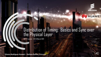
SSM (Synchronization Status Message) in SyncEGiulio Bottari—SSM required to prevent timing loops and to support reference selection (as per SDH)— Details according to G.781 and G.8264—In SDH SSM delivered in fixed locations of the SDH frame— Packet based mechanism required in case of SyncE—OUI (organizationally unique identifier) from IEEEreused to specify exchange of QLsover the OAM specific slow protocol (OSSP)Sync—Option 1 clock treated as G.813controloption 1 (QL-SEC), Option 2 as an G.812Selector Btype IV clock (QL-ST3)Systemclock—Two types of protocol message types are definedSSUSSUSelector CSSM communicationsSelector CTxTxSynccontrolRxRxSelector BSystemclockG.8264-Y.1364(14) F11-1— "heart-beat" message (once per second)— Event message generated immediately—SSM QL value is considered failed if no SSM messages are received after a five second period2020-10-28 Page 18
Ethernet synchronization messaging channel(ESMC) FormatGiulio Bottari—ESMC PDU with QL TLV always sent as the first TLV in the Data and padding fieldOctet numberSize/bitsField1-66 octetsDestination Address 01-80-C2-00-00-02 (hex)7-126 octetsSource Address13-142 octetsSlow Protocol Ethertype 88-09 (hex)151 octetSlow Protocol Subtype 0A (hex)16-183 octetsITU-OUI 00-19-A7 (hex)19-202 octetsITU Subtype21bits 7:4 (Note 1)Versionbit 3bits 2:0 (Note 2)22-243 octets25-153236-1490 octetsLast 44 octetsOctet numberSize/bitsField18 bitsType: 0x01Event flagReserved2-316 bitsLength: 00-04Reserved4bits 7:4 (Note)0x0 (unused)bits 3:0SSM codeData and padding (See point j)FCSNOTE – Bit 7 of octet 4 is the most significant bit. The least significant nibble, bit 3 to bit 0 (bits 3:0)NOTE 1 – Bit 7 is the most significant bit of octet 21. Bit 7 to bit 4 (bits 7:4) represent the four-bitversioncontainsthe four-bit SSM code.number for the ESMC.NOTE 2 – The three LSBs (bits 2:0) are reserved.—Recently extended to carry new clock types (and inform on PRTC traceability)—Extended QL TLV—Use of Padding bits also recently revised (set to all zero and ignored by receivers)2020-10-28 Page 19
Octet numberSize/bitsField12-348 bits16 bits8 bitsType: 0x02Length: 0x0014Enhanced SSM code (see Table 11-6)5-1264 bitsSyncE clockIdentity of the originatorof the extended QL TLV, Note1,13148 bits8 bitsFlag; Note2Number of cascaded eEECs from thenearest SSU/PRC/ePRC158 bits16-2040 bitsNumber of cascaded EECs from thenearest SSU/PRC/ePRCReserved for future useNote: ePRC SSM code (0x23) added in 20182020-10-28 Page 20Extended QL TLVGiulio BottariSyncE clockIdentityfollows the IEEE 1588 rulesClockQuality levelEnhanced SSM codeEEC1QL-EEC10xFFEEC2QL-EEC20xFFOther clock typesQL message0xFFcontained(refer to the QL TLV)in [ITU-T G.781]Note 1Note RCQL-ePRC0x23Note 1: Tables 11-8 and 11-9 illustrate the full set of clock types from [ITU-TG.781]
SSM codes for SyncETable 11-7 (G.8264-2017): Option IClockQualitySSM code Enhanced SSU-BQL-SSU-B10000xFFEEC1QL-EEC110110xFFNote 00x21eEECQL-eEEC10110x22ePRCQL-ePRC00100x23Note 1: There is no clock corresponding to this qualitylevel.Note 2: When processing the SSM QL, The SSM codeshould be processed first, followed by processingthe Enhanced SSM code.If a clock supports both the QL TLV and the extended QL TLV,it should set the SSM code and the enhanced SSM codeaccording to table 11-7/11-8, and send both the QL TLV and theextended QL TLV.2020-10-28 Page 21Giulio BottariTable 11-8 (G.8264-2017): Option IIEnhanced SSMcodePRSQL-PRS00010xFFNote 0xFFNote 1QL-PROV11100xFFNote 10x21eEECQL-eEEC10100x22ePRCQL-ePRC00010x23Note 1: There is no clock that corresponds to this quality level.Note 2: When processing the SSM QL, The SSM code should beprocessed first, followed by processing the Enhanced SSM code.ClockQuality levelSSM codeNote: ePRC SSM code (0x23) added in 2018
Characters for Embedded characters:!"# %&'()* ,./0123456789:; ?@ABCDEFGHIJKLMNOPQRSTUVWXYZ[\] abcdefghijklmnopqrstuvwxyz{ } ¡ § ª« ²³ ¶· ¹º»¼½ÀÁÂÃÄÅÆÇÈËÌÍÎÏÐ
the received clock and pass it to the system clock. — Synchronization Status Message as per G.8264 — Enhanced SyncE recently approved (G.8262.1) — Recently generalized as physical layer based clock (SEC, Synchronous Equipment Clock) — It does not transport Time — but it was proposed — All nodes must support SyncE: sync chain as per .