Transcription
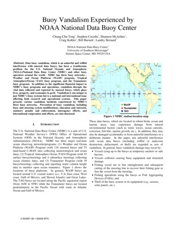
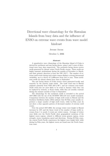
An Incomplete Manual for Building aBASIC OBSERVATION BUOY (BOB) BASICSINTRODUCTIONA Basic Observation Buoys (BOB) are anchored in shallow, protected areas of the Bay.FLO (Fixed Local Observations) is a device that is fixed to a piling or dock structure.Flo’s are problematic because the length of cable between the sensor and the datalogger cannot be too long. Data transmission between the sensor and the logger is lessefficient with increasing cable length. Presently, the limit is about 4 meters (12 ft).BOBs and FLOs are designed to collect a variety of weather and water quality data.Presently, the data logger does not allow for automated data uploading. The datacollected by these devices must be manually retrieved, evaluated, and then uploaded toa local computer. In the future the data will be telemetered to a remote computer orInternet site for automatic archival. The data quality is dependent on the sensor systemused to collect the data and the rigor and protocol used to calibrate the sensors. Thedata collected from BOB utilizes a Pasco GLX data logger (www.Pasco.com) and isDouglas R. Levin, PhDdoug.levin@noaa.gov757-710-1631
compatible with PASCO software DataStudio. It has not been evaluated with regards tomeeting National Data Buoy Center (NDBC) standards.A goal of the BOB design is to be able to collect quality data for two weeks withoutmaintenance, and infrequent need for additional sensor calibration. This goal has notyet been achieved.A Pasco GLX data logger is presently being used on BOB/FLO. A list of sensors thatcan be deployed with BOB are being tested (Table 1). Appendix 1 shows a picture, theBOB Sensors1.2.3.4.Water Quality SensorWeather Sensor*Thermocline SensorFlow Rate & TempTemp, pH,DO*,ConductivityEverything but wind speed (see 8)Water Temp, Water DepthCurrent Velocity, but not directionAdditional Sensors that add to the data stream5.6.7.8.Light SensorSound Level3-Axis AccelerometerWeather/Wind SpeedCloud Cover MonitoringAmbient sound levelsSmall Wave MeasurementTemp, Pressure, Humidity, Dew Point, Wind ChillAccessory Sensors that do not necessarily add to the data stream.9. GPS PositionRecords position of sample pointWater Quality Parameters that can be measured at the site, but not by BOB/FLO10. Colorimeter11. Wind Speed & Direction12. Turbidity SensorTitrations for Ammonia, Nitrate, PhosphatesNot for buoy system and not weather proofNot flow through – Measures water clarityThe PASCO Dissolved Oxygen Calibration is not yet accurate when measurementsare more than one hour apart.model number, cost, and a brief description of the parameters measured by the sensor.THE BOB BUOY KITStudents build the BOB/FLO, install and calibrate the sensors, and get them ready fordeployment. Initial deployment of the systems can be supported by a dedicated fieldcrew, i.e. a local river keeper or marina operator. Station crews (the schools/communityprograms that built them) are trained to calibrate the data systems, troubleshootproblems, and learn the steps necessary to swap out sensor modules and data storageDouglas R. Levin, PhDdoug.levin@noaa.gov757-710-1631
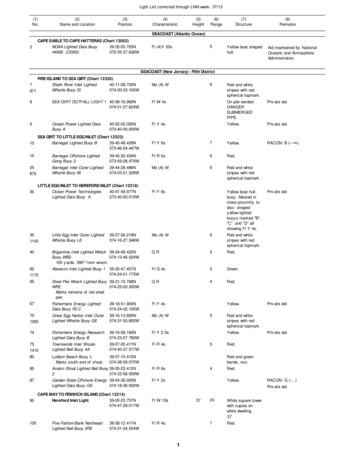
units. Both BOBs and FLOs are designed as modular kits. Each system can be fittedwith the sensors that fit the need and budget for the water body being investigated. BOBconsists of 3 main assemblies; the Buoy Body, the Sensor Cage, and the Mast.The Buoy Base – Or “What makes it float?”The buoy body floats on a 24” square of 4” PVC pipe. These pieces are sealed withcalk to prevent leakage. Three additional, sealed, floatation “tubes” are placed betweenthe float “square” to provide more floatation and help keep the buoy floating if sectionsof the floatation leak.Note: A 10ft section of 4”, Schedule 40, PVC pipe is cut into8, 15” pieces.Using a power miter saw, sometimes referred to ascompound miter saw, cut the pipe into 8 - 15” pieces. Fourpieces will be used to make the outer ring, or square, of thebuoy. Three will be used to make the inner float. There willbe one extra 15” piece of 4” pipe left over.4 pieces of 4” Schedule 40 PVC pipe cut into15” sections.Douglas R. Levin, PhDdoug.levin@noaa.gov757-710-1631
4 - 90o 4” Schedule 40 PVC elbows.Assemble the outer ring by inserting the 15” straight pieces between the elbows.Create the square outer “ring” of the Buoy. Apply a relatively slow drying glue to thepipe end pieces. It is not recommended to use the Oatey PVC Cement. This glue setsalmost immediately and fuses the PVC pieces together. When the external buoy ring isbuilt its important that it lies flat. This can be achieved by putting the four sides andelbows together and (carefully) standing on the opposite corners. This makes certainthat the buoy ring structure is flat (i.e. does not rock on a flat surface).Douglas R. Levin, PhDdoug.levin@noaa.gov757-710-1631
The inner floatation system has a couple of purposes. One is to add to the buoyancy ofthe buoy allowing more payload. Second, because this series of floatation devices aresealed and independent, it offers added security if one of the other cylinders or theexternal buoyancy ring leaks.The auxiliary floats are closed cylinders 15” in length. Take three of your 15” lengthsand install the pipe caps on either end. You can use a glue and/or calk to minimize thechance of leaks.Douglas R. Levin, PhDdoug.levin@noaa.gov757-710-1631
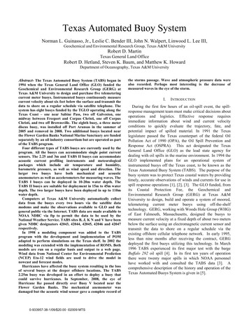
Prepare Three Auxiliary FloatsCut two 60” lengths of the Oatey 33927 ¾” x 100’ Plastic Hanger Strap. Wrap the straparound the three auxiliary floats making certain that the loop is inside the end caps. Puta nail through the small holes in the strap to hold it in place and drill out the holes oneither side (use a 3/8” drill, or a size that a little larger than the plastic cable tie)This is a close up of the nail in the strap. The holes in the strapon either side of the nail have been marked for drilling. Byenlarging the holes plastic cable ties can be used to create theloop in the straps.Pull the strap ends taught so they form a loop around the threeauxiliary floats. Don’t worry too much about them being tight.We’ll take care of that in the next step. Thread two cable tiesthrough the strap ends to secure the loop that keeps theauxiliary floats together.Douglas R. Levin, PhDdoug.levin@noaa.gov757-710-1631
Note the whitish cable tie endbetween the two blue ones.“Double-up” the cable ties so youhave one long one that will reacharound the lower and upper loop ofthe pipe strap. Cinch the cable tieend making the strap that circlesthe 3 auxiliary floats taught so thatthe end caps are held togethertightly.In this view you can seethe white plastic cabletie “cinching” thebottom and top strap.This will keep the threeauxiliary floats together.Do the same for thestrap on the lower partof the Auxiliary Floatsystem. You’ll come upwith an assembly thatlooks like the picturebelow.Douglas R. Levin, PhDdoug.levin@noaa.gov757-710-1631
Now we’ll attach this to the largerfloat ring.Put the auxiliary float system insidethe external float “square”. Cut 72”lengths of the Oatey 33927 ¾” x 100’Plastic Hanger Strap. Weave thislonger strap through the centerbuoyancy system and around theouter ring. Note that this strap istucked under the system that youconstructed earlier to hold the threeauxiliary floats together. Follow thesame procedure to secure the endsof this strap. Then, again, double upon the cable ties and “cinch” thestrap in the four spots shown on theoverall image.Douglas R. Levin, PhDdoug.levin@noaa.gov757-710-1631
This is the completed Base of the Basic Observation Buoy. The mathematical solutionsfor determining the buoyancy of this structure can be found in Appendix II.Building the Buoy PlatformIn this stage of BOB construction we’llbe creating the platforms that the datalogger and sensors are then installed inand on. The Buoy Body consists of twopieces of plastic pegboard. The bottomplatform is fastened to the floats withplastic cable ties. The upper platform isattached, and separated from the bottomplatform by a set of 4 12” galvanized orstainless steel bolts.Douglas R. Levin, PhDdoug.levin@noaa.gov757-710-1631
Get the 2’ x 4’ sheet of plastic peg board out. We’vegot to measure and mark it for cutting.Mark the 2’ x 4’ piece of PegMaster so you cut it in half,creating two pieces that are 2’ x 2’. Cut it with a jigsaw.Make sure you follow safety procedures beforecutting. Use eye protection and ear protection.Know where the cord is so that you don’t cutthrough it. In theend you’ll have twopieces of the plasticpeg board. We willcut the corners offof what will becomethe upper platform.Douglas R. Levin, PhDdoug.levin@noaa.gov757-710-1631
The diagonal cuts of the corners run 9 holes in the x & y direction. Then “connect” thedots. Do this for all four corners.You’ll end up with a bottom and top platform for the buoy. When the top piece is placedover the bottom piece you’ll have an overlap that reveals the corners of the lowerplatform (that looks like what’s in the image below). in the next image you see thisindividual corner in more detail.In this frame, the “T” represents the top platform,and the “B” the bottom platform.Douglas R. Levin, PhDdoug.levin@noaa.gov757-710-1631
So, now you have a lower and an upper buoy platform. Now we’ll connect them with aseries of bolts.For the lower part of platform, you will need toprepare four (4) sets of these; One 12” long bolt, 3flat washers, 1 6” piece of ½” PVC Schedule 40pipe, and a 5/8” nut.Now, get the two platform pieces and get them ready to drill the holes that the bolts willbe inserted through.It’s a little hard to tell from the glare, but the fourplatform bolt holes are positioned 12” from eitheredge and 3.5” from the platform edge. Or, you canmeasure 12” from the edge and put the holebetween the third and forth pegboard holes, aswas done here. I use a 9/16” wood bit to drillcleanly through the plastic.Douglas R. Levin, PhDdoug.levin@noaa.gov757-710-1631
Do this on all four sidesand you’re ready toinstall the platform bolts.When I drill these holes, Istack the upper andlower platforms in theorientation that they willbe in when the structureis built. This insures thatthe four bolt holes will beperfectly aligned and theinstalled bolts will bevertical (not slanted).While we’re at it, we might as welldrill the other holes for the sensorcage assembly and the centermast. For the sensor cageassembly, you’ll need to drill twoholes to accommodate two bolts.The attachment will look like itdoes in the following picture.Mark the two spots on the lower square platformpiece where the sensor assembly will attach toit. These can be located by counting 6 holesfrom one edge and 5 from the other, as seen inthis picture.Douglas R. Levin, PhDdoug.levin@noaa.gov757-710-1631
Do the same for the opposite side ofthe pegboard piece.Enlarge the hole at the intersection with a 7/16” wooddrill bit. When you install the sensor assembly, the boltwill slide right through. Ok. we’re done here for now.Once the holes are drilled it’s time to installthe platform bolts.Put a 5/8” washer on a 12” bolt and slide it upunder the lower platform.Where the bolt goes through the lowerplatform place a 5/8” washer so the platformplastic is sandwiched between the lower bolthead and washer and the washer you justinstalled. Now, put the 6” PVC sleeve overthe washer and the bolt threads. Now, putanother flatwasher over the PVC sleeve. Spina nut down until it is snug against the sleeveand the bold is able to standup. You shouldhave about 6” of additional thread left to workwith. Repeat this for each of the four holes.Douglas R. Levin, PhDdoug.levin@noaa.gov757-710-1631
You’ll end up with a platform with fourbolts to which you’ll attach the upperplatform.Now thread a nut down onto the threads leaving about an inch ofthe bolt end exposed. Slide a 5/8” washer onto the nut. Thesebecome the surface on which the upper platform will rest. Repeatthis procedure for all four of the platform bolts.Next, take the upper buoy platform with the drilled holes and slide itover the four bolts The upper platform should rest on the washersabove the nut you “staged” on the bolt below. Don’t worry about itbeing level right now. We’ll get to that in a minute. Now put another5/8” washer so it rests on the pegboard, put a 5/8” lock washer overthat, and add the final 5/8” inch nut. Finger tighten this for now.Initially, to make the upper platform level, adjustthe nut system just below the platform, andsimultaneously tighten the upper nut so that thebolt end is flush with the nut edge. This will giveyou a working platform that we can attach to thebuoy floatation system.Douglas R. Levin, PhDdoug.levin@noaa.gov757-710-1631
This is the two-stage, buoy platform that we’ll affix to the buoy floatation frame.Douglas R. Levin, PhDdoug.levin@noaa.gov757-710-1631
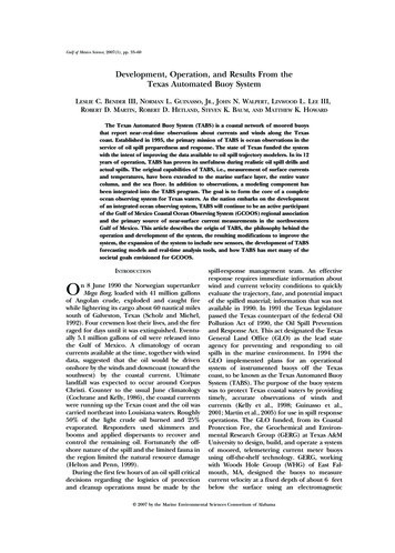
THE SENSOR CAGEThe sensor cage is designed to hold 4 water quality sensors provided by Pasco(www.pasco.com). Note in the picture below that the sensor cage can be rotated to anangle so that its low point is above the bottom of the Buoy float. This keeps the sensorsfrom resting on the bottom when low tide empties a site of water.The Sensor Cage is built using PVC fittings obtained from www.pvcfittings.com. The tiltfeature of the cage allows the user to rotate the sensors so that the bottom of the cagewill not be in direct contact with bay bottom in the event of a low water, low tide event.This means that you should avoid gluing the joints where the rotation occurs. Thesejoints are highlighted in red in the parts figure.Putting the cage together is not much different than Legos, with a plan. In the followingseries of images we’ll piece the sensor cage together. Before you glue the piecestogether, I recommend building the whole cage and make sure of the fit. This will insurethat you end up with a straight sensor cage. Get the feel of what you’re going to end upwith before you start gluing.Douglas R. Levin, PhDdoug.levin@noaa.gov757-710-1631
The parts are shown in the figure below and are listed as follows:2 – 9” lengths of ½” PVC4 – 90 degree elbows4 – T fittings4 – 4-way fittings (be sure that the internal piping is clear of burrs)8 – 1” pieces of PVC6 – 3” pieces of PVC - note that there is a hole drilled through these to allow water tocirculate for better water quality measurements.The small 1” pieces are what hold thebigger pieces together.Douglas R. Levin, PhDdoug.levin@noaa.gov757-710-1631
When you’re ready, glue the endsand jam them into the adjoiningpieces. Use glue that doesn’t dryinstantly in case you make amistake.Start by grabbing a 4-wayconnector, a 3” section of ½” pvc,and a T. Put together the basicsensor holder. Then put 1” jointpieces in the side of the 4-way andT-joint so we can put four of theseassemblies together.With the 1” joint pieces in placepush the sensor holder assemblytogether.Douglas R. Levin, PhDdoug.levin@noaa.gov757-710-1631
With the 1” joint piece in place addthe 90 degree elbow to the sensorcage end.The sensor cage should lie flat withthis piece connected, i.e. It shouldpoint vertically (not angled).Prepare to add the third and fourthsensor holder by adding the 1” jointpieces to the crosses and the T’s.Douglas R. Levin, PhDdoug.levin@noaa.gov757-710-1631
The third section is ready to beadded.The third section is added.Prepare to add thefourth sensorholder.Douglas R. Levin, PhDdoug.levin@noaa.gov757-710-1631
The fourth sensorholder is added.With the sensorcage complete we’llnow add the elbowon the other side.The elbow is readyto be attached tothe sensor cage.Don’t glue theelbows on if youwant to be able torotate the sensorcage.Douglas R. Levin, PhDdoug.levin@noaa.gov757-710-1631
The elbow attached to thecompleted sensor cage.The complete 4-sensorsensor cage. 3” pvcextenders have beeninserted into the elbows.The completed structure isalmost ready to be hungfrom the buoy platform.Attach the upper elbow to the3” ½” PVC piece. Then attachthe 9” ½” PVC piece to theother opening of the elbow.Douglas R. Levin, PhDdoug.levin@noaa.gov757-710-1631
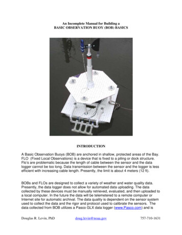
This image is what the finishedsensor cage looks like from theside.This is a front view of thecompleted sensor cage.It’s ready to be attachedto the buoy.Douglas R. Levin, PhDdoug.levin@noaa.gov757-710-1631
Attaching the Sensor Cage to the Buoy PlatformNow we’ll put together the system used to affix the sensor cage to the lower buoyplatform. It consists of the following pieces:2 – 3” 3/8” Galvanized or Stainless Steel Bolts6 – 3/8” Flat washes2 – 3/8” Lock washers2 – 3/8” Nuts2 – ½” PVC T’sIt attaches to the lower platform of the buoy in a mannersimilar to the way we put the bigger platform bolts in. Inan earlier stage you drilled the holes that these boltswould attach to.Take the assembly apart. Slide a 3/8” flat washer ontothe bolt and then through the pegboard of the lowerplatform.On the top side of the bolt, sandwich the plasticplatform with another 3/8” flat washer and slide the “T”fitting over the bolt. The threads should (better) comeout the top of the fitting. Now, put another 3/8” flatwasher over the top of the T, as shown, a lock washer,as shown, and top it off with the 3/8” nut, as shown.Tighten these nuts down.Douglas R. Levin, PhDdoug.levin@noaa.gov757-710-1631
The Sensor Cage Structure can now be attached to the Buoy. Attach it by pushing theextensions of the sensor cage into the T-fitting of the bolt you’ve attached to the buoyplatform.The Data Logger NestThe Data Logger is housed inside a small plastic case.The Mast Options.To say that the mast design is imperfect is an understatement. There is some debatethat simply adding a mast that collects air temperature 1m off of the water surface isenough. If this is elected for BOB, then the following instructions will suffice. In the eventyour group has chosen to add a more substantial meteorological monitoring component,jump to the second mast design.Douglas R. Levin, PhDdoug.levin@noaa.gov757-710-1631
For simply adding a mast to attach an air temperature sensor above the water surface,you’ll need to drill a hole in the center of the upper platform and gather the followingparts.1- 1m length of ½” PVC1- Lasco Pt No 436-005 – check to make sure that a ½” PVCgoes into the non threaded end.1-1/2” Rigid conduit LocknutDrill a 7/8” hole, using a wood bit, in thecenter of the upper platform. Drillanother ½” hole about 2” to the side ofthe center hole.Thread the lasco 1/2” male adapter throughthe mast, with the threads to the bottom.Fasten it in place by, again, sandwiching theplastic pegboard with the conduit nut on thetop side of the buoy platform.Douglas R. Levin, PhDdoug.levin@noaa.gov757-710-1631
In the case where a simple temperature sensor is going to be deployed on the mast, it ispossible that the sensor cabling can be “fished” or threaded through the mast PVC. Thesecond hole that was drilled can also be used to thread sensor cables from the datalogger below.This is what the BasicObservation Buoy with the simpletemperature recording mastoption.Douglas R. Levin, PhDdoug.levin@noaa.gov757-710-1631
Installing a more substantial mast for weather data recordingA crudely engineered mast has been designed that accommodates a moresophisticated weather measuring system. What it lacks most is an ability to accuratelymeasure wind speed and direction. There is no easy way to measure wind direction ona rotating buoy, so we’re limited to measuring wind speed.The pieces required to build this are:Douglas R. Levin, PhDdoug.levin@noaa.gov757-710-1631
APPENDIX 1Datalogger & Sensors for BOB/FLOData LoggerPS-2002 Pasco GLX 329Large backlit LCD -- visible in both sunlight and low lightStand-Alone or Computer Interface4 universal sensor ports4 built-in sensors (2 temperature, sound, voltage)Collect Data in the Classroom or the FieldGraphs, tables, digits, and meter displaysPrints graphs and data directly to printersSensorsThe following sensors offered with the GLX can be installed onto a BOB/FLO.Water Quality PS-2169Temperature (water and/or air)pHDissolved OxygenConductivity (note that conductivity & temperature salinity) 369 79** 225** 108**** If purchased separatelyThermocline SensorPS-2151Douglas R. Levin, PhDdoug.levin@noaa.gov 269757-710-1631
Measures water depth changesMeasures water temperature (at depth)3-Axis Acceleration Sensor 185 Weather/AnemometerFor measuring small waves(This sensor has not been tested on BOB)PS-2174 Water Quality Colorimeter 129Not an in-situ measurementUsed w/titration kitsAnalyze for ammonia, nitrate, phosphatesFlow Rate and Water Temperature 179TemperatureBarometric PressureRelative and Absolute HumidityDew PointWind Speed* (not direction)Wind ChillInstallation method still in design phasePS-2179 Douglas R. Levin, PhDPS-2119PS-2130 129An impeller on a stickdoug.levin@noaa.gov757-710-1631
Current Velocity Measurements (w/o direction)Requires a vane to point in direction of currentGPS PositionPS-2175 159 Automatically records position of sampleNot necessary for BOB/FLO in fixedlocation. Position can be measured once by a“loaner” GPS.High Sensitivity Light SensorPS-2176 Light SensorTemperature/Sound Level/Light Douglas R. Levin, PhDStudy cloud coverPS-2106A 133 59Study cloud cover w/ less accuracy than 2176PS-2140 98Combination, air temp, cloud cover, ambient sounddoug.levin@noaa.gov757-710-1631
Turbidity SensorPS-2122 Not a flow through sensorMeasure water clarityWeather SensorPS-2154A Wind Velocity Accessory 109Barometric PressureAbsolute & Relative HumidityDew PointTemperatureRelative AltitudeNo wind so orientation is not an issueME-6812 Douglas R. Levin, PhD 125 99Wind Velocity & Direction from a dockNot for a buoy systemNot weather proofdoug.levin@noaa.gov757-710-1631
Appendix IICalculations of Buoy Buoyancy and Payload Size ConsiderationsThe objective is to determine how much water (in weight) the buoy displaces. So, first, calculateits volume. Then, using the specific weight of water (62 lb. per cubic foot) determine how muchweight of water would be displaced if the structure was completely submerged. Then, subtractfrom that the actual air weight of the object. This gives give you its reserve buoyancy, or anamount of payload you can add to it before it sinks.So, why don’t we fill the floats with foam? Even if you were to fill the tubes with foam, itdoesn't increase the buoyancy. In fact, it decreases it slightly by the weight of the foam.However, the upside is that the foam displaces airspace that would fill up with water in the eventof a leak, which would quickly subtract from any reserve buoyancy available (assuming the foamwasn't absorbent).Mathematically, the equation for buoyancy is calculated by determining the volume of the objectand subtracting the air weight of the object (put it on a scale). The resultant number is the reservebuoyancy.The equation is(Vol of air inside the object (ft3) x 62 lb/ft 3 – (air weight of object in lbs) Reserve BuoyancyThe volume of a cylinder equals the (area of the base)*height ¶r2hwhere ¶ Pi, or 3.14r the radius of the cylinder’s inner wall.h the height of the cylinderAn online cylinder volume calculator can be found by “googling”cylinder volume calculator or going directly tohttp://referencedesigner.com/calc/cal 07.phpHere are the calculations for the buoy base:Each side of the external ring is 20”. The inside wall ofthe Schedule 40 is 4”.Douglas R. Levin, PhDdoug.levin@noaa.gov757-710-1631
The volume of each side 0.134 ft 3The volume of the whole external ring 0.536 ft3The volume of air inside the external ring 0.536 ft3 x 62 lb/ft 3 33.23 lbs.The buoyancy of the external ring is 33.23 lbs.The air weight of the external ring is 15 lbs.The reserve buoyancy for the external ring is 33.23 – 15 18.23 lbsEach auxiliary float is 15” long. The inside wall of the Schedule 40 is 4”.The volume of each 15” float 0.101 ft3The buoyancy of each auxiliary float 0.101 ft3 x 62 lb/ft3 6.26 lbs.The added buoyancy of 3 auxiliary floats 3 x 6.26 18.78 lbshe air weight of the auxiliary float structure is 8.1 lbs.The reserve buoyancy for the auxiliary float structure is:18.78 – 8.1 10.68The summed buoyancy of the external ringand three auxiliary floats is:10.68 18.23 28.9 lbs.Douglas R. Levin, PhDdoug.levin@noaa.gov757-710-1631
The weight of the buoy platform, data logger, protective case, and sensors is: 12 lbs.The reserve buoyancy on BOB after subtracting the platform is:28.9 – 12 16.9 lbs.Douglas R. Levin, PhDdoug.levin@noaa.gov757-710-1631
Appendix IIIQtyBuoy Body Parts4208412147621 rollDescription12" 1/2" Galvanized Bolts5/8" Flat Washers Galvanized1/2" Flat Washers5/8" Locknut Galvanized3/4" Nut GalvanizedPlastic Peg (Pegmaster) Board 2' x 4'4" 90' Elbows15" Lengths 4" PVC Sch 40 PVC Pipe4” End Caps for Auxiliary Floats15" Lengths 1 1/2" PVC LengthsOatey Pipe StrapSensor Cage26226442683" 3/8" Galvanized Bolts3/8" flat washers3/8" lock washers3/8" Nut Galvanized1/2" PVC T's1/2" PVC Elbows (90')1/2" PVC Cross1/2" PVC 9" lengths1/2" PVC 3" lengths1/2" PVC 1" lengthsMast Assembly11111111With Meteorological Sensor (see manual for w/o Met Sensor)Lasco D2466 2" x1/2" Sch 402" PVC Sch 40 10" Length15" Length 1 1/2" PVC Lengths4" length 1/2" PVC11" length 1/2" PVC1/2" coupling assembly1/2" Conduit Clamp4" length Temflex Rubber TapeDouglas R. Levin, PhDdoug.levin@noaa.gov757-710-1631
2111" stainless or galvanized machine screws, washers, nutsStainless U-Bolt no. 1326" Plastic Putty KnifeDouglas R. Levin, PhDdoug.levin@noaa.gov757-710-1631
Douglas R. Levin, PhD doug.levin@noaa.gov 757-710-1631 compatible with PASCO software DataStudio. It has not been evaluated with regards to meeting National Data Buoy Center (NDBC) standards. A goal of the BOB design is to be able to collect quality data for two weeks without