Transcription
Gulf of Mexico Science, 2007(1), pp. 33–60Development, Operation, and Results From theTexas Automated Buoy SystemLESLIE C. BENDER III, NORMAN L. GUINASSO, JR., JOHN N. WALPERT, LINWOOD L. LEE III,ROBERT D. MARTIN, ROBERT D. HETLAND, STEVEN K. BAUM, AND MATTHEW K. HOWARDThe Texas Automated Buoy System (TABS) is a coastal network of moored buoysthat report near–real-time observations about currents and winds along the Texascoast. Established in 1995, the primary mission of TABS is ocean observations in theservice of oil spill preparedness and response. The state of Texas funded the systemwith the intent of improving the data available to oil spill trajectory modelers. In its 12years of operation, TABS has proven its usefulness during realistic oil spill drills andactual spills. The original capabilities of TABS, i.e., measurement of surface currentsand temperatures, have been extended to the marine surface layer, the entire watercolumn, and the sea floor. In addition to observations, a modeling component hasbeen integrated into the TABS program. The goal is to form the core of a completeocean observing system for Texas waters. As the nation embarks on the developmentof an integrated ocean observing system, TABS will continue to be an active participantof the Gulf of Mexico Coastal Ocean Observing System (GCOOS) regional associationand the primary source of near-surface current measurements in the northwesternGulf of Mexico. This article describes the origin of TABS, the philosophy behind theoperation and development of the system, the resulting modifications to improve thesystem, the expansion of the system to include new sensors, the development of TABSforecasting models and real-time analysis tools, and how TABS has met many of thesocietal goals envisioned for GCOOS.INTRODUCTIONOn 8 June 1990 the Norwegian supertankerMega Borg, loaded with 41 million gallonsof Angolan crude, exploded and caught firewhile lightering its cargo about 60 nautical milessouth of Galveston, Texas (Scholz and Michel,1992). Four crewmen lost their lives, and the fireraged for days until it was extinguished. Eventually 5.1 million gallons of oil were released intothe Gulf of Mexico. A climatology of oceancurrents available at the time, together with winddata, suggested that the oil would be drivenonshore by the winds and downcoast (toward thesouthwest) by the coastal current. Ultimatelandfall was expected to occur around CorpusChristi. Counter to the usual June climatology(Cochrane and Kelly, 1986), the coastal currentswere running up the Texas coast and the oil wascarried northeast into Louisiana waters. Roughly50% of the light crude oil burned and 25%evaporated. Responders used skimmers andbooms and applied dispersants to recover andcontrol the remaining oil. Fortunately the offshore nature of the spill and the limited fauna inthe region limited the natural resource damage(Helton and Penn, 1999).During the first few hours of an oil spill criticaldecisions regarding the logistics of protectionand cleanup operations must be made by thespill-response management team. An effectiveresponse requires immediate information aboutwind and current velocity conditions to quicklyevaluate the trajectory, fate, and potential impactof the spilled material; information that was notavailable in 1990. In 1991 the Texas legislaturepassed the Texas counterpart of the federal OilPollution Act of 1990, the Oil Spill Preventionand Response Act. This act designated the TexasGeneral Land Office (GLO) as the lead stateagency for preventing and responding to oilspills in the marine environment. In 1994 theGLO implemented plans for an operationalsystem of instrumented buoys off the Texascoast, to be known as the Texas Automated BuoySystem (TABS). The purpose of the buoy systemwas to protect Texas coastal waters by providingtimely, accurate observations of winds andcurrents (Kelly et al., 1998; Guinasso et al.,2001; Martin et al., 2005) for use in spill responseoperations. The GLO funded, from its CoastalProtection Fee, the Geochemical and Environmental Research Group (GERG) at Texas A&MUniversity to design, build, and operate a systemof moored, telemetering current meter buoysusing off-the-shelf technology. GERG, workingwith Woods Hole Group (WHG) of East Falmouth, MA, designed the buoys to measurecurrent velocity at a fixed depth of about 6 feetbelow the surface using an electromagneticE 2007 by the Marine Environmental Sciences Consortium of Alabama
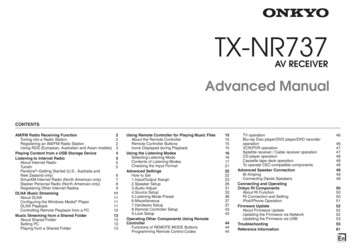
34GULF OF MEXICO SCIENCE, 2007, VOL. 25(1)current sensor and transmit the data to shore ona regular schedule via the existing offshorecellular telephone network. In early 1995, lessthan 9 mo after receiving the contract, GERGdeployed the first five buoys using this technology. In March 1996 TABS experienced its firstmajor test with the barge Buffalo 292 oil spill(Lehr, 1997). In its first 10 yr of operation therehave been 20 major spills in which NationalOceanic and Atmospheric Administration(NOAA) personnel have worked with and consulted the TABS data (Martin et al., 2005).The primary mission of TABS is to providenear–real-time data when a spill occurs. However, the GLO recognized from the inception ofthe project that three factors would form TABSinto an effective public resource as well. Thus,the GLO supports research to improve thereliability, operational range, and versatility ofthe TABS buoys; it insists that all TABS data beimmediately disseminated through a user-friendly Internet website; and it encourages otherscientific research projects to build on the TABSresources. To that end, the buoys have beencontinuously improved since the original designto incorporate new technology, lessons learnedin the field, and expanding mission goals. Fromits inception in 1995, when the concept of a userfriendly Internet was just beginning to emerge,the buoy observations have been made availableto the GLO and the general public on theInternet. In 1998 a modeling component wasadded to the TABS program with the development and implementation of the PrincetonOcean Model (POM), adapted to performsimulations on the Texas shelf. In 2002 theRegional Ocean Modeling System (ROMS) wasimplemented for the Texas shelf, but with a gridthat covered the entire Gulf of Mexico. In orderto complement the numerical models, a statistically based methodology for achieving optimalnowcasts of the shelf-wide circulation was startedin 2003. Also in 2003 real-time analysis of thedaily observations was included, which provides the user with quality controlled oceanographic, meteorological, and engineering products. (see http://tabs.gerg.tamu.edu/Tglo/RTA//RTA index.html)Today the TABS buoy network consists of 10actively monitored sites, eight along the coastand two on either side of the Flower GardenBanks National Marine Sanctuary. The eightcoastal sites are funded by the GLO: one nearSabine Pass, two off Galveston, one midwaybetween Freeport and Corpus Christi, two offCorpus Christi, and two off Brownsville. Thestate of Texas has funded TABS at a level ofabout 700,000 per year in fiscal years 2002–2007. The two Flower Garden Banks sites arefunded separately (a yearly average of 350,000from 2001 to 2006) by an oil industry consortium, but are operated as part of the TABSprogram. The GLO-supported inshore sites offof Galveston and Corpus Christi have beenoccupied continuously since 2 April 1995.Figure 1 shows the locations and Table 1 liststhe coordinates of the 10 actively monitoredsites, as well as the discontinued sites.TABS was, to the best of our knowledge, thefirst offshore observing system in the Gulf ofMexico. The Texas Coastal Ocean ObservingNetwork (TCOON; http://lighthouse.tamucc.edu/TCOON/HomePage) began earlier withthree stations in 1991 and has expanded tomore than 40 stations today, but it focuses onwater level on the coast and inshore waters.The Physical Oceanographic Real-Time s.html) has been operational in Tampa Baysince 1990–1991 and in Galveston Bay/HoustonShip Channel since 1996–1997. The Wave-Current-Surge Information System for CoastalLouisiana (WAVCIS; http://wavcis.csi.lsu.edu/)is operated by the Coastal Studies Institute ofLouisiana State University. It began with its firststation (CSI 13) in 1998 (Zhang, 2003); todaythere are six operational stations in water depthsranging from 5 m to 21 m. The Coastal OceanMonitoring and Prediction System (COMPS;http://comps.marine.usf.edu/), operated bythe University of South Florida, was implemented in 1997 for the West Florida Shelf (Merz,2001). It consists of a real-time array of bothoffshore buoy and coastal stations (Weisberg etal., 2002). A comprehensive list of all theobserving systems that are part of the Gulf ofMexico Coastal Ocean Observing System(GCOOS) is provided at http://ocean.tamu.edu/GCOOS/System/insitu.htm.The purpose of this article is to present anoverview of the development, operation, andresults of running the TABS operational coastalobserving system on the Texas shelf for the past12 yr. The paper is organized in six sections:Development, Field Operations, Data Management, Modeling, Achievements, and Conclusions. The Development and Field Operationssections provide a review of the development,capabilities, and operational experience of theTABS system. The section on Data Managementdescribes the measures used to retrieve, store,and quality control the observations, the stepsused for the real-time analysis of the qualitycontrolled observations, and the steps taken todisseminate the data and the products. Thesection on Modeling discusses the development
BENDER ET AL.—TEXAS AUTOMATED BUOY SYSTEM35Fig. 1. Map displayed on the TABS Internet home page showing the location of the TABS buoys as well as theNOPP and LSU buoys, the NOAA CMAN weather stations, and the NOAA NDBC weather buoys that are linked tothe TABS Internet home page. Bathymetry contours are shown for the 20-, 50-, 200-, 2,000-, and 3,500-m depths.and implementation of the numerical andstatistical models used to complement andenhance the buoy observations. The section onAchievements highlights a few of the moresignificant results of the TABS system, includinghow TABS has worked with NOAA during oilspills and how we have endeavored to meet thesocietal goals of the Integrated Ocean ObservingSystem. Finally, the Conclusions section summarizes the article and outlines the futuredevelopment of TABS.DEVELOPMENTThe mandate of the TABS system is to provide high-quality, near-surface current measurements. At its most basic level, each TABSbuoy records vector-averaged currents at a fixeddepth of 1.8 m below the surface, does so every30 min, and transmits the current speed anddirection to shore once every 2 hr. In order toaccomplish this mission, the buoy consists offour principal subsystems: the oceanographicand meteorological sensors, the communicationslink, a solar-powered electrical system, and thebuoy flotation structure (Chaplin and Kelly,1995). Until recently the flotation structurefor all TABS buoys was a spar design. Aspar buoy provides a stable platform for makinghigh-quality, low-noise current measurementsbecause it does not respond to high-frequencywaves like the more common discus buoy usedby the National Data Buoy Center (NDBC).A spar buoy does not have the reserve buoyancy,power, and payload capacity that a discus buoyhas, and this has placed acceptable constraintson the versatility and operational range of thebuoys.
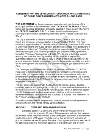
36GULF OF MEXICO SCIENCE, 2007, VOL. 25(1)TABLE 1. Locations of TABS feetfeetLatitude (N)Longitude (W)Date first u01.328993u37.260921 June 19952 April 19952 April 199531 May 199531 May 199522 Feb. 199611 March 19974 June 199713 May 199813 May 199820 April 199820 April 199820 April 199815 Aug. 199927 July 199819 Feb. 199928 Nov. 200123 Jan. 2002aThese buoy locations have been discontinued. Data are available in the website archive.The buoy H site was reoccupied on 27 Aug. 2005, after being discontinued in 1998.These buoys were operated by a project funded by the NOPP, Office of Naval Research through Dynalysis of Princeton. Funding ended in CY1999and operations ceased. N was resurrected as part of the FGBJIP in 2002.dThis buoy was operated by a project funded by the Minerals Management Service through Louisiana State University. Funding ended in CY1999 andoperation has ceased.eBuoys N and V are operated on behalf of a consortium of oil companies operating in the vicinity of the Flower Garden Banks National MarineSanctuary.bcTABS I.—The original spar buoys, designatedas TABS I and first deployed in 1995, weredesigned for the near-shore coastal environmentand were intended to obtain near-surface currents and water temperature. Urethane Technologies, Inc. of Denham Springs, LA, fabricatedthe buoy with a flotation package of closed-cell,cross-linked, polyethylene foam with a polyurethane fabric-reinforced skin. A Marsh McBirney,Inc. (MMI) electromagnetic two-axis 585-currentsensor was used to measure water velocities.Woods Hole Group (WHG), in addition toassisting with the design, manufactured theoriginal computer system that ran the buoy.The cellular telephone network operated byPetrocom for the offshore oil industry providedthe means for the near–real-time observations.The buoy was equipped, as are all buoys, with anintegral radar reflector in the upper mast anda Coast Guard–approved amber night flashinglight. A schematic of the buoy in its present formis shown in Figure 2. The system and samplinginformation of the TABS I buoy is detailed inTable 2, which lists the measurements made byeach buoy type, the sensors used, the elevation ofthe sensors, the sampling time, the averaginginterval, and the telemetry acquisition frequency.The design has been continuously improvedsince the original TABS I buoy went to sea.During the first 5 yr of the program, the designwork was subcontracted to WHG, but beginningabout 7 yr ago (2000) the design work wastransferred in-house. From the beginning ofthe TABS program, all of the assembly, wiring,system upgrades, and maintenance on the buoyshas been done at GERG’s facilities at Texas A&MUniversity. In 2001 the hull was redesigned toutilize structural aluminum alloys to make thebuoy more robust and serviceable. The top endcap of the buoy was also redesigned to takeadvantage of the increased hull diameter andnewer antenna designs, which enabled theantenna to be mounted inside the protectivecovers of the buoy. The new tops were equippedwith 10,000-psi bulkhead connectors for allcables to provide hull integrity and increasesurvivability should the buoy become submergedduring collision or storm. This modification wasthe result of lessons learned in the field whenflooding of the mast occasionally occurredthrough the cable glands. After these changes,there have been no broken antennas on a TABSI buoy nor have any of the buoys flooded.Major changes in the TABS I buoys werealso made in the current sensor, the onboardcomputer system, and the communication link.After a few years of operations, many of theMarsh McBirney sensors developed saltwaterleaks that affected data availability. These sensorshave all been replaced with a single-point, vector-
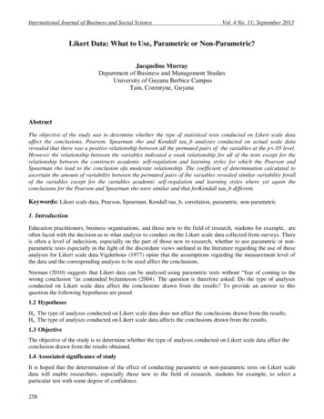
BENDER ET AL.—TEXAS AUTOMATED BUOY SYSTEM37Fig. 2. Schematic of TABS I (far right), TABS II (middle two: leftmost with downward-looking RDI ADCP andAanderaa DCS 4100R and rightmost with Aanderaa DCS 4100R only) and 3-m discus buoys (far left) fabricated atGERG. The older style Windsonic anemometers are depicted on the two TABS II buoys. Buoys are to scale.averaging, acoustic Doppler sensor manufacturedby Aanderaa Data Instruments AS of Norway, theDoppler Current Sensor (DCS) 3900R and DCS4100R. This acoustic sensor is significantly lesssusceptible to fouling (see Fig. 3) than the MMIsensor and has proven to be very reliable in thefield (Walpert et al., 2001). The 4100R is a newgeneration of the 3900R sensor, designed so thatthe electronics are housed outside the Durotongplastic material that encapsulates the Dopplerceramics. This change was made by the manufacturer in mid-2005 to address the problem offailure in the DCS tilt sensors. In conjunction withthe change to the DCS current sensor, the systemelectronics for the TABS I were re-designed. Thenewly designed electronics made use of a singleRemote System Manager (RSM)/daughterboardcombination and eliminated three electronicboards from the system. The new system was alsodesigned to allow the attachment of ancillarysystems such as the Seabird MicroCat C/T sensors.Digital satellite communications are now available at costs less than the original offshorecellular telephone service first used in the TABSI buoy. All TABS buoys now use the QualcommGSP-1620 Packet Data Modem, which uses theGlobalstar satellite network as the primarycommunication link. The Globalstar Corporation provides the satellite data-link service,utilizing a constellation of 48 low-earth orbitsatellites that can transfer data at a rate of9,600 bps. This communications link is fasterand more reliable than the cellular system usedby the original TABS buoys. The average datatransmission success rates have increased tomore than 97%, whereas individual buoys havehad long stretches, i.e., months, in which thetransmission rate is 99.9%.The power system for the TABS I buoy imposesconstraints on the number and type of sensorsand onboard systems that can be accommodated.The 6-inch interior hull diameter of the TABS Ispar buoy provides a physical limitation to thesize of the instrument compartment and the areaavailable on the mast for solar panels. Consequently each TABS I buoy contains two 12V DCgel cell batteries, each with 144 watt hourscapacity at full charge and six 10-watt multicrystalline silicon solar panels made by BP Solar.Even in winter the solar panels are capable of
GPSMeteorologicalSite elevationSensor raphicMeteorologicalaOceanographic––––sea level1.8 m below site elevation1.8 m below site elevationNone––––NoneBuoy orientation for windsAir temperatureRelative humidityAir pressureCurrentsWater temperatureTemperature/conductivityWindsAir temperatureRelative humidityAir ionelevationelevation–Buoy tilt compensation for windssitesitesitesitesitesitesiteAanderaa DCS 4100ROptionalOptionalAanderaaOptionalGill Instruments Wind Observer II UltrasonicAnemometer Model 1390Honeywell HMR 3300 Digital Compass or a ShaevitzAccuStar II Dual Axis ClinometerEither a KVH C100 compass or a Honeywell HMR 3300digital compassEither a Rotronics MP101A or an RM Young 41342VC ina radiation shieldRotronics MP101AVaisala PTB 100Asea levelAanderaa DCS 3900R–––––1.8 m below1.8 m below1.5 m below3.4 m above3.4 m above3.4 m above3.4 m aboveGarminAanderaa DCS 4100RYYYYYYYYTABS IIaAanderaa DCS 3900RYYYNNNNNTABS ICurrents: speed, direction, buoy orientationand tiltSeawater temperaturebADCPAcoustic modemConductivity and temperatureConductivity, turbidity, and transmissometerWind speed and directionCurrent speedCurrent directionSeawater temperatureWind speedWind directionAir temperatureRelative humidityAir pressureMeasurementsTABLE 2. TABS buoy system and sampling parameters.38GULF OF MEXICO SCIENCE, 2007, VOL. 25(1)
–––Relative humidityAir pressure5 min average of ping data takenonce every second, tilt and buoyorientation simultaneously strobedat 1 HzInstantaneous: taken at the end ofthe 5 min sampling period–Every 30 min, starting on the hourand half-hourEvery 2 hr beginning at 0000 GMTAir temperatureWindsfSeawater temperatureCurrentseFor all sensorsFor all sensorsQualcom GSP-1620 Packet DataModem utilizing the GlobalstarLEO satellite communicationsnetworkSystem ARGOSTABS IInstantaneous: taken at the end of the 5 min samplingperiod10 min average of 25 ms sampled data, except for windgusts which is the maximum speed recorded in the10 minInstantaneous: taken at the end of the 10 min samplingperiodInstantaneous: taken at the end of the 10 min samplingperiodInstantaneous: taken at the end of the 10 min samplingperiod5 min average of ping data taken once every second, tiltand buoy orientation simultaneously strobed at 1 HzEvery 30 min, starting on the hour and half-hourEvery 2 hr beginning at 0000 GMTSystem ARGOSQualcom GSP-1620 Packet Data Modem utilizing theGlobalstar LEO satellite communications networkTABS IIaaOnly the TABS II buoy is capable of carrying a meteorological package. Wind speed and direction, air temperature, and barometric pressure are always measured. The instruments on the met package are interchangeable;consequently a humidity sensor is optional.bThe Aanderaa current sensor provides an integral seawater temperature sensor.cCurrent velocity and seawater temperature only, no net data.dIn the event of an incident we have the ability to increase the acquisition frequency and sampling time.eCurrents are tilt compensated and oriented to magnetic north onboard the buoys.fWinds are tilt compensated and oriented to magnetic north onboard the buoy.MeteorologicalAveraging intervaldOceanographicSampling timeBackup telemetrycAcquisition frequencydMain telemetryMeasurementsTABLE 2. Continued.BENDER ET AL.—TEXAS AUTOMATED BUOY SYSTEM39
40GULF OF MEXICO SCIENCE, 2007, VOL. 25(1)Fig. 3. Barnacle encrusted Aanderaa DCS 3900 sensor recovered from site R after a 6-mo deployment. Thevelocity data were acceptable in spite of this level of fouling.fully recharging the batteries on a sunny day. Atfull charge the buoy can operate for 45 d inovercast skies when little if any charging occurs.TABS II.—In 1997, after a year-and-a-half ofsuccessful field operations with the TABS Imodel, the GLO directed GERG to develop animproved and more capable TABS buoy. GERGworked with manufacturers to design and builda ‘‘second-generation’’ version of the spar buoy,known as TABS II. The TABS II was originallydesigned with four major enhancements: 1)operation in regions with poor or no cellularphone coverage using the Westinghouse HS1000satellite telephone system (Globalstar was notavailable at the time and Geostationary Operational Environmental Satellite (GOES) did notprovide two-way communications that was needed); 2) an increased size of the flotation packagefor deployment in water depths greater than100 ft (30 m); 3) an ARGOS satellite data transmission system that is automatically activated ifthe primary communication link fails, and; 4)a Climatronics TAC Met meteorological packageto measure wind speed and direction. Since theinitial TABS II buoys were designed and success-fully deployed, several modifications have beenmade to improve the reliability, robustness, anddata quality of the TABS buoy (Magnell et al.,1998). The original TABS II design, which incorporated the MMI current sensor, was upgradedto the Aanderaa DCS 3900R and DCS 4100R inconjunction with the change made in the TABS Icurrent sensor. The original meteorological package was redesigned to use a Gill acoustic windvelocity sensor and now includes sensors tomeasure air temperature, humidity, and barometric pressure. In 2001 the TABS II design wasfurther modified to incorporate a downwardlooking acoustic Doppler current profiler (ADCP)in addition to the surface measurement with theAanderaa DCS velocity sensor.Beginning in 2001 the original Westinghousesatellite telephone system was replaced with theQualcomm satellite data modem (GSP-1620),which operates on the Globalstar satellite datanetwork. The greatest drawback of the use of theWestinghouse system on a spar buoy was itstuned 37-inch antenna. The antenna was thegreatest failure point of the buoy because of itsinconsistent tuning response and its vulnerabilityand exposure to damage. The Qualcomm data
BENDER ET AL.—TEXAS AUTOMATED BUOY SYSTEMmodem made use of a much smaller antenna (4inch diameter by 2.5-inch height), reported dataat a higher rate, and required half the power andhalf the space of the Westinghouse system. Newradio frequency cables from Times MicrowaveSystems were incorporated to improve the datatransmission through the bulkhead fittings.These were eventually bypassed by locating thedigital modem in a water-tight housing on thetop of the buoy. The first system was deployed onbuoy ‘‘N’’ and went in the water on 23 Jan. 2002.Since then the modem has been extremelyreliable (working even when buoys are lying ona ship’s aft deck while in transit to be deployed)and has been incorporated as the primarycommunications link on all TABS buoys.All TABS buoys now have a redundant, independent, communications link based on theService ARGOS satellite system. ARGOS providesboth location information and data-collectionservice worldwide using three polar-orbitingsatellites. The communication link for two ofthe ARGOS satellites is such that data can be sentby the buoy only while a satellite is passingoverhead, whereas the third satellite, launchedin Oct. 2006, has two-way capability. Eachsatellite makes six to eight passes per day. Thetimes of the passes are predictable, but notevenly spaced. The data transfer rate is4,800 bps, but the message length can only be32 bytes. Consequently only the surface currentsand battery voltage data can be included in themessage. Although limited, this system is reliable, consumes little power, can be equippedwith a short, easy to waterproof antenna (important for improving the robustness of the buoy tovandalism), and is economical. The computersoftware of all the TABS buoys recognizes whenthe primary communications system is notfunctioning and automatically switches to theARGOS mode. Operation of the ARGOS backupsystem is enabled automatically once every 10 d.In 2004 and 2005, GERG fabricated four newTABS II buoys based on the original TABS II hulldesign, but with an all new electronics andcomputer system of our own design in lieu of theoriginal WHG design. The newest buoys have anintegrated high-resolution temperature and conductivity cell and a GPS system as standardsensors. They also have the capability of accepting additional sensors such as ADCPs, turbiditysensors, transmissometers, and acoustic modemsto retrieve data from bottom-mounted instrumentation such as wave gauges or upwardlooking ADCPs. A schematic of the buoy in itspresent form is shown in Figure 2. The systemand sampling information of the TABS II buoyare detailed in Table 2, which lists the measure-41ments made by each buoy type, the sensors used,the elevation of the sensors, the sampling time,the averaging interval, and the telemetry acquisition frequency.GERG considers software as one of the criticalcomponents of any observing system. The buoycontroller software needs to be extremely robustand capable of diagnosing and repairing problems when possible and sending diagnosticinformation ashore when errors or faults aredetected. Errors that cannot be corrected autonomously on the buoy have to be repairable froma shore base via telemetry. As part of the newTABS II buoys, GERG designed and developeda new buoy controller based on the PrometheusPC-104 computer system manufactured by Diamond Systems Corporation. The computer usesTiny Linux as the operating system and systemprograms that are written in Perl and C. ThePrometheus is a small footprint computeroperating at 100 MHz with multitasking ability,powerful computational ability, large storagecapacity, and relatively low power consumption.The computer is interfaced to three proprietaryboards developed at GERG: an ADCP powersupply board that provides a clean 54 volts forADCP operation; a sensor interface board thatenables two-way communication with all thedigital sensors as well as control over analogsensors; and a 12-channel power switch boardthat turns power on and off to each individualsensor according to program requirements. Thisprovides the operator with total control overeach sensor schedule and provides the ability toremotely change the schedule or samplingregime whenever required. A Windows-basedgraphical user interface (GUI) that interfaceswith the Linux-based software on the buoy makesit possible for technicians without a Unix background to effectively communicate, set up, makechanges, and test the buoys either remotely viasatellite, through the existing WIFI system, orthrough a hardwired monitor port.Of the six buoys GERG fabricated using thePC-104–based controllers, only one has failed orreset in the field. The one failure occurred whena hard disk on board the buoy filled with imagefiles due to a malfunctioning instrument. Part ofthe reason for the success of these buoys is thatthe software running on the PC-104 is robust andself-diagnosing. The buoy software was engineered in modular form to enable easy sensoror system updates to be uploaded via satellite,hardwire, or over the integrated WIFI system.The buoy software monitors its own operationand reports any problems in the form ofdiagnostic files that are transmitted with thedata. The software monitors the system voltage,
42GULF OF MEXICO SCIENCE, 2007, VOL. 25(1)system current, charge and discharge rates of thebatteries and is capable of running sensordiagnostics on individual sensors at any timethey are required.The power system for the TABS II buoy mustmeet greater demands than the TABS I buoy,primarily because of the increased number andtype of sensors that are accommodated and thenew PC-104 computer. The 22-inch interiordiameter of the TABS II spar buoy providesa large
buoy flotation structure (Chaplin and Kelly, 1995). Until recently the flotation structure for all TABS buoys was a spar design. A spar buoy provides a stable platform for making high-quality, low-noise current measurements because it does not respond to high-frequency waves like the more common discus buoy used by the National Data Buoy Center .