Transcription
MAG-SMFILL-MAGElectromagneticFlowmeterwith AC Magnetic FieldExcitationModels: DS21 / DS4 FInstruction BulletinD184B064U02 Rev. 03 / 08.02For Converters:MAG-SM Model 50SM1000FILL-MAG Model 50ES7000
You have purchased a high quality, modern Electromagnetic Flowmeter Systemfrom ABB Automation. We appreciate your purchase and theconfidence you have expressed in us.This Instruction Bulletin contains information relating to the assembly andinstallation of the instrument and the specifications as well the testing of thisinstrument design. ABB Automation reserves the right to make hardware and softwareimprovements without prior notice. Any questions which may arise that are notspecifically answered by these instructions should be referred to our main plant inGöttingen, Germany or to one of our Technical Sales Bureaus.Their addresses, telephone and FAX numbers may be found on the back cover.This interference resistance of this converter complies with theNAMUR-Recommendations “EMC-Guidelines for Manufacturersand Users of Electrical Instruments and Equipment “Part 1, 5/93 and EMC-Guideline 89/336/EWG(EN50081-1, EN50081-2)Copyright by ABB Automation. All rights reserved.
Introductory Safety Notes for the EMF SystemRegulated UsageThe Electromagnetic Flowmeter System (EMF) is manufactured to state of the art designs and is safe tooperate.The flowmeter is to be installed exclusively in applications which are in accord with the specifications.Every usage which exceeds the specifications is considered to be non-specified. Any damages resultingtherefrom are not the responsibility of the manufacturer.The user assumes all risk for such usage.The applicable specifications include the installation, start-up and service requirements specified by themanufacturer.Assembly, Start-Up and Service PersonnelPlease read this Instruction Bulletin and the safety notes before attempting installation, start-up or service.Only qualified personnel should have access to the instrument.The personnel should be familiar with the warnings and operating requirements contained in thisInstruction Bulletin.Assure that the interconnections are in accordance with the Interconnection Diagrams. Ground theflowmeter system.Observe the warning notes designated in this document by the symbol:Hazardous Material InformationIf a repair is required, the following information should be noted:In view of the Disposal Law of 27 Aug. 86 (AbfG. 11 Special Wastes) the owner of special wastesis responsible for its care and the employer also has, according to the Hazardous Material Law of01 Oct. 86 (GefStoffV, 17 General Protection Responsibility), a responsibility to protect his employees, wemust make note thata) all flowmeter primaries and/or flowmeter converters which are returned to ABB Automation Products forrepair are to be free of any hazardous materials (acids, bases, solvents, etc.).b) the flowmeter primaries must be flushed so that the hazardous materials are neutralized. Thereare cavities in the primaries between the metering tube and the housing. Therefore after meteringhazardous materials, these cavities are to be neutralized (see Hazardous Material Law -GefStoffV). Fortwo piece housings the housing screws should be loosened. For flowmeter primaries 14"/DN 350 thedrain plug at the bottom of the housing is to be removed in order to neutralize any hazardous materialin the magnet coil and electrode areas.c) for service and repairs written confirmation is required that the measures listed in a) and b) have beencarried out.d) any costs incurred to remove and neutralize the hazardous materials during a repair will be billed to theowner of the equipment.
ContentsPage1.Flowmeter Primary and Converter Coordination . 11.11.21.31.41.5Application Areas for MAG-SM . 1Application Areas for FILL-MAG . 1Model Number Coordination . 1Instruction Bulletins . 1Specification Sheets, Metering System MAG-SM ABB Part No.:D184S034U01 Rev.01 Fill-MAGD184S033U01 . 12.Overview, Flowmeter Primary Designs . 23.Functional Description . 34.Assembly and Installation . pection . 4Installation Requirements Flowmeter Primary . 4Installation of the Flowmeter Primary . 6Installations for Protection Class IP 68 . 8Installation of the High Temperature Design . 8Installation in Larger Size Pipelines . 8Installation of the Certified Designs . 9Replaceable Parts List, Connection Box, Aluminum Housing 12” / DN 300 . 11Replaceable Parts List, Connection Box, Aluminum, Flowmeter Primary 14” - 16” : DN 350 - 400 . 12Replaceable Parts List, Connection Box, Aluminum, Flowmeter Primary 20” : DN 500 . 13Replaceable Parts, Flowmeter Primary . 14Replaceable Parts List with Preamplifier . 155.Safety Relevant Section of the Instruction Bulletin . 165.15.1.15.1.25.1.35.1.45.1.55.1.65.1.7Electrical Connections Anschluss . 16Grounding . 16Supply Power Connections . 18Magnet Coil Supply . 18Power Consumption . 18Signal Cable Connections . 19Interconnection Diagram . 19Connection Area . 206.Start-Up . 226.16.26.3Preliminary Checks . 22Zero Check . 22Maintenance . 227.Testing and Error Search of the Flowmeter Primary Using the Converter*) . 23
Flowmeter Primary, Model DS21 /DS4 F1.!Flowmeter Primary and ConverterCoordinationinstalled in the pipeline and a converter mounted separately. In order to assure trouble free operation it is essential toassure that only converters Model Numbers 50SM1000 or50ES7000 are connected to the flowmeter primary. Thecomplete Model Numbers are listed on the instrument tagsof the instruments.NoteThis flowmeter system utilizes AC magnetic field excitation.The metering system consists of a flowmeter primary whichisFlowmeter System with AC Magnetic Field Excitation1.1Application Areas for MAG-SM1.2These electromagnetic flowmeters provide an economical andprecise means to meter the flow of liquids, slurries and sludgeswhose electrical conductivity is above 20 µS/cm (option, 0.5 µS/cm). The metering system is especially suitable for fast changing processes, two-phase liquids, continuous or pulsating flows(piston pump operation).Application Areas for FILL-MAGThese electromagnetic flowmeters are especially designed forbatch, fill and injection processes, for filling the smallest volumes all the up to the largest containers.1.3Model Number CoordinationFlowmeter PrimaryConverterStainless Steel Housing Series 200010DS2111/10DS2112, DS21MAG-SMFill-MAG50SM100050ES7000Aluminum Housing Series truction BulletinsFlowmeter PrimaryConverterABB Part No.: D184B064U01 Rev.02MAG-SMFill-MAGABB Part No.:D184B085U01 Rev.01D184B066U011.5MAG-SMFill-MAGABB Part No.:D184S034U01 Rev.01D184S033U01Specification Sheets, Metering System1
Flowmeter Primary, Model DS21 /DS4 F2.Overview, Flowmeter Primary DesignsVariable Connections1/10”–1-1/2” / DN3-DN402”–4” / DN 50–DN 100Connection TypesWeld stubsHose connectorPipe fittingFood industry fittingExternal threadsTri-ClampInternal threadsFlangePVC-Cement sleeveSMS-FittingFixed-ClampFixed FlangeFixed Flange1/10”–1-1/2” / DN3-DN40See Spec. Sheet for more,others upon requestAccuracyFlowmeter primary housing mat’lWafer Design2”–4” / DN 50–DN 1001 % of rateStainless Steel Housing Complete Series 2000Alum Hsg. Series 4000Flowmeter PrimaryModel NumberDS21*DNPNDS21FMeter Size Pres. Rtg.DS21WDNPNDS41FMeter Size Pres. Rtg.Process ConnectionsInchWafer DesignFlanges DIN 2501Flanges ANSI B16.5Flanges FAB1B DIN 11864-2BAseptic connection. DIN 11864-1BFood Industry fitting. DIN 11851Threaded connection. SMS 1145Weld stubs DIN 11850Weld stubs DIN 2463Weld stubs ISO 2037Tri-Clamp DIN 32676Tri-Clamp ISO 2852Fixed clampExternal threads ISO 228Internal threads ISO 228PVC-Cement sleeveHose connector1/8” Sanitary connectorLiner–W–1/10–4 3–100 10–40––FDN 3-100PN10-40–DN 3–2000PN 10–401/10–43–10010 F1/10”–4” CL 150–300–1/10”–40” CL 150–3001/10–43–10016 L–––1/10–43–100 10-40 A–––1–425–100 16 S–––1–425–100 16 D–––1/10-43–10010 R–––1/10-43–10010 Q–––1–425–100 40 P–––1–425–100 10 T–––1/10-43–100 10-40 U–––3/8–1-1/2 10–4010 C–––1/10–13–2510 10 G–––1/10–1/2 3–1510 H–––1/25–3/32 1–210 B–––PEEK, Torlon ( 1/10” : DN3)PFAPFAHard and soft rubber,PFA ( 3/32” : DN2)PTFE, PFA, others 20 µS/cm Option 0.5 µS/cmSS 316Ti/1.4571, SS 1.4539, Hastelloy B-2/C-4, Platinum-Iridium, Tantalum, TitaniumSS316L/1.4404, 304/1.4301SS 316Ti/1.4571–Steel, SS 316Ti/1.4571IP 67 / IP 68IP 67 / IP 68IP 67 / IP68IP 67 / IP 68-25 to 130 C-40 to 130 C-25 to 130 C-25 to 130 C/180 CConductivityElectrodesProcess connection materialProtection Class per EN 60529Fluid temperature*InchApprovalsHygienic and sterile requirements!2CIP/SIP-capable FML, 3A, EHEDG (Cleanability)NoteThe maximum signal cable length between the flowmeterprimary and the converter is 50 m. When a preamplifier isinstalled for low conductivity applications the max. signalcable length is 200 m. The flow velocity must be reduced, 1 m/s, when the fluid conductivity is low and the εr value ishigh (for demineralized water εr 78).CIP-capable
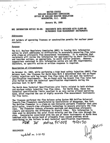
Flowmeter Primary, Model DS21 /DS4 F3.Functional DescriptionABB Automation Electromagnetic Flowmeters »EMF« are theideal flow metering instruments for liquids, slurries and sludgeswhich have a specific minimum electrical conductivity. Theinstruments measure accurately, add no additional pressuredrop, have no moving or protruding parts, are wear free andchemically resistant. The flowmeters can be readily installed inexisting pipelines.The ABB Automation EMFs have been proven over many yearsof service and are the preferred flowmeters in the ChemicalIndustry, Municipal Water and Waste Water treatment facilities,the Food and Beverage Industry as well as in the Pulp andPaper Industry.Principle of OperationThe basis for the operation of electromagnetic flowmetersare Faraday’s Laws of Induction. A voltage is induced in aconductor as it moves through a magnetic field.This measurement principle is applied to a conductivefluid which flows in a pipe through which a magnetic field isgenerated perpendicular to the flow direction,see Electromagnetic Flowmeter Schematic.UE B D vshows that the signal voltage UE is linear and proportional tothe volume flowrate.UE qvDesignAn electromagnetic flowmeter system includes a flowmeterprimary and a converter. The flowmeter primary is installedin the pipeline while the converter which processes the flowsignals can be mounted locally or in a central control room.!Note:Please observe the specified coordination between theflowmeter primaries and the converters shown on Page 1.Principle of Operation MAG-SM with CapacitiveSignal MeasurementsThe basis for the operation of electromagnetic flowmetersare Faraday’s Laws of Induction. A voltage is induced in aconductor as it moves through a magnetic field.The voltage which is induced in the fluid is measured at twoelectrodes located diametrically opposite to each other. Thevoltage is measured capacitively, i.e., the electrodes do notcome in contact with the fluid.The voltage which is induced in the fluid is measured at twoelectrodes located diametrically opposite to each other. Thisflow signal voltage UE is proportional to the magnetic inductionB, the electrode spacing D and the average fluid velocity v.Each electrode forms a coupling capacitor with the insidewall of the lined meter tube on which the flow signal potentialexists whose dielectric is the liner material. The flowrateproportional measurement signal is fed to the input of anintegrated preamplifier over this coupling capacitor.Noting that the magnetic induction B and the electrode spacingD are constant values indicates that a proportionality existsbetween the flow signal voltage UE and the average flowvelocity v. The equation for calculating the volume flowrateThis flow signal voltage UE is proportional to the magneticinduction B, the electrode spacing D and the average fluidvelocity v.Magnet CoilMagnet CoilMeter Tube inElectrode PlaneMeter Tube inElectrode PlaneMeasurement ElectrodeFlow Signal VoltageMeasurement ElectrodeUEBDvqv Flow signal voltage Magnetic induction Electrode spacing Average flow velocity Volume flowrateFlow Signal Voltage2D π*) qv ---------- v4Fig. 1Electromagnetic Flowmeter Schematic3
Flowmeter Primary, Model DS21 /DS4 F4.Assembly and Installation4.1InspectionBefore installing the electromagnetic flowmeter primary checkfor mechanical damage due to possible mishandling duringshipping. All claims for damage are to be made promptly to theshipper prior to installation.4.2Installation Requirements FlowmeterPrimaryThe flowmeter primary and the signal cables should not beinstalled in close proximity to strong electromagnetic fields.The flowmeter primary must be installed so that the meter tubeis always completely filled with fluid and cannot drain. A slightupward slope of approx. 3% is desirable to prevent gas build upwithin the flowmeter (Fig. 2 ).Fig. 3In horizontal installations the imaginary line connecting theelectrodes should be horizontal so that air or gas bubblescannot affect the flow signal voltage. This electrode orientationis shown in Fig. 4 .Electrode Axis3 Fig. 2Vertical installations are ideal when the fluid flows inan upward direction. Installations in drop lines, i.e., the fluidflows from the top to the bottom are to be avoided becauseexperience has shown that it is not possible to guarantee thatthe pipeline will always remain 100% full and that an equilibriumcondition between the upward flowing gas and the downwardflowing fluid will not occur.Generally, the flowmeter primary should be installed in the pipeline with the cable connectors pointing downward. If the flow direction with this arrangement does not agree with the flowdirection indicated by the arrow on the flowmeter primary, theprocedures described in Section Preliminary Checks should beemployed.!Fig. 4For a free flow in- or outlet an invert should be providedto assure that the flowmeter primary is always filled with fluid(Fig. 5 ).CommentsThe figures for the EMF flanged designs shown inSection Installation Requirements Flowmeter Primary alsoapply to the other process connection types e.g. WaferDesign, aseptic connections, 1/8“sanitary connections,hose connectors, Tri-Clamp, screwed flanges and others.Fig. 54
Flowmeter Primary, Model DS21 /DS4 FIn a free flow outlet (drop line) the flowmeter primary should benot be installed at the highest point or in the discharge of thepipeline (meter tube could drain, air bubbles, Fig. 6 ).For heavily contaminated fluids a bypass line as shown in Fig.8 , Design A is recommended, so that the flowmeter may bemechanically cleaned without shutting down the process.Fig. 6The measurement principle is independent of flow profile aslong as standing eddies do not extend into the measurementsection (e.g. after double elbows, tangential inflows or half openvalves upstream of the flowmeter primary). In such situations,measures to condition the flow are required. Experienceindicates that in most cases a straight upstream section with alength of 3 x D and a downstream section of 2 x D is sufficient(D flowmeter primary size Fig. 7 ). The reference conditionsfor test stands, per DIN 19200, require a straight upstreamlength of 10 x D and a 5 x D straight length downstream. ForVolume Flow Integrators additional installation requirementsare mandatory. See Installation of the Certified Designs Section4.2.5 on Page 9.AABBFig. 8When it is anticipated that the electrodes may become coatedwith an insulating layer, a bypass line as shown in Fig. 8 ,Design B, should be installed. For flowmeter primaries installedin the vicinity of pumps or other vibrating equipment theutilization of mechanical dampers is advantageous (Fig. 9 ).Fig. 7Fig. 9Wafer valves are to be installed in such a manner that thewafer, when open, does not extend into the flowmeter. Valvesor other shut off devices should be installed downstream so thatthe flowmeter primary cannot drain.An automatic empty pipe detector option is available in theconverter which uses the existing electrodes for its input.5
Flowmeter Primary, Model DS21 /DS4 F4.2.1 Installation of the Flowmeter PrimaryThe electromagnetic flowmeter can be installed at any arbitrarylocation in the pipeline as long as the installation requirements(Page 4) are satisfied. Installation dimensions may be found inthe appropriate Specification Sheet. At the same time, careshould be exercised when selecting the installation site toassure that moisture cannot enter into the connection area.Exercise care to assure that the housing cover gaskets arecorrectly seated when installing the covers after the installationand start-up have been completed.Electrode AxisFor installations in horizontal pipelines make sure that neitherelectrode is located at the highest point. Any gas or air bubbleswhich may be present in the fluid could interrupt the electricalconnection between the electrodes and the fluid. The idealinstallation conditions for an EMF are assured in a verticalinstallation. The preferred orientations are shown in Fig. 10 .GasketsIt is essential to use the gaskets which are included with theflowmeter primary shipment. Only when these gaskets areused and the flowmeter primary has been installed correctlycan leaks be avoided. Observe the information in Table 1.FILL-MAG Flowmeter Primary InstallationGenerally, the flowmeter primary should be installed in thepipeline with the cable connectors pointing downward.Wafer Design flowmeter primaries with are shipped withoutgaskets. The installation (axisymmetric and parallel) is madedirectly into the pipeline without gaskets. Only when a grounding plate is installed is an additional gasket required (groundingplate / pipeline flange). See Table 3 for torque specifications.For all other flanged flowmeter primary designs commerciallyavailable gaskets are to used made of materials compatiblewith the fluid being metered and suitable for the operatingtemperatures (rubber, It, PTFE, etc.). See Tables 2 and 3 fortorque specifications.!Note:Graphite should not be used to lubricate the flange orprocess connection gaskets because an electricallyconductive coating could form on the inside surface of themeter tube adversely affecting operation.The flowmeter primary should not be installed in closeproximity to strong electromagnetic fields. Steel parts (e.g.mounting brackets should be spaced at least 100 mmdistant from the flowmeter primary). Vacuum shocks shouldbe avoided to prevent damage to the liner.Comment:A vacuum resistant liner is available in the program.Any valves or relays used in the system should incorporateappropriate measures to reduce interference signals such asprotection diodes, varistors or R-C combinations (VDE 0580)If the flow direction with this arrangement does not agree withthe flow direction indicated by the arrow on the flowmeterprimary the following procedure can be employed so that thecontact outputs respond correctly for reverse flow conditions.Steps to reverse the direction indication:a) For a Standard- and Ex-flowmeter primaries the shielded signalleads (only at the primary) are to be interchanged.Interchange terminal 1 with terminal 2.Interchange terminal 1S with terminal 2S.Electrode Axisb) For flowmeter primaries with preamplifiers only terminals1 and 2 (at the flowmeter primary) are to be interchangedbecause terminals 1S and 2S are used for the preamplifiersupply voltage U and U- of 12 V DC.Control, Signal and Supply Voltage Cables!Note:The flowmeter primary should not be installed inclose proximity to strong electromagnetic fields. It isrecommended that the control-, signal- and supplypower cables be routed separate from one another. It isadvantageous to install the cables in grounded metalconduits. Multiple cables of the same type may beinstalled in the same conduit.HorizontalInstallationsFig. 106Electrode AxisVerticalInstallations
Flowmeter Primary, Model DS21 /DS4 FGasket Surfaces on the Mating FlangesTorque SpecificationsIn all installations parallel mating flange surfaces should beprovided and suitable gaskets used. Only then can leaks beavoided. The flange gaskets for the flowmeter primary must beinstalled concentrically to achieve optimum measurementresults. The parallel gasket surface requirements for themating flanges are: OutsideParallel GasketSurfaces InsideFlowmeter PrimaryInchDN1/10 – 1/4 3 – Required Parallel Gasket Surface Inside mm Outside 9Table 1Protection PlatesThe protection plates for the PTFE/PFA/ETFE lined flowmeterprimaries have been installed to prevent damage to the linerduring shipment. Remove these protection plates only whenready to install the meter in the pipeline. Be careful not to cut orotherwise damage the liner in order to prevent leakage. TheDimension Drawings for your instrument design may be foundin the Specification Sheet.Torque Specifications for FlangesThe mounting bolts are to be tightened equally in theusual manner without excessive one-sided tightening. Werecommend that the bolts be greased prior to tightening andthat they be tightened using a wrench with a normal length, ina crisscross pattern as shown in Fig. 11 . Tighten the boltsduring the first pass to approx. 50%, during the second pass toapprox. 80% and only during the third pass to 100% of the max.torque value. The max. torque values should not be exceeded,see the following tables.LinerMeter SizeInchDNProcessConnectionPFA/PTFE/HardRubber( 1/2”:DN 15)ETFE( 1”:DN 25)1/10-3/8 s,WaferDesignPFA 10”:DN 250PTFE/Hard RbrETFE 12”:DN 300456810121416100125150200250300350400PTFE 32”:DN 47278BoltsTorqueMax. NMPNbar4 x M124 x M124 x M124 x M124 x M164 x M164 x M168 x M168 x Design, 4”:DN1008 x M168 x M168 x M2012 x M2012 x M2412 x M2416 x M2416 x 0900100012001400160018002000Flanges20 x M2420 x M2724 x M2724 x M3028 x M3028 x M3332 x M3636 x M3940 x M4544 x M4548 x 0101010101012001400160018002000Flanges32 x M3036 x M3340 x M3344 x M3648 x M3936548050062072566666Table 2Max. Torque Values for PTFE-Envelope GasketsLinerMeter SizeInchDNProcessConnectionBoltsPFA1/10-5/16 3-8Wafer DesignVariableConnectionsPFATorqueMax. NMPNbar4 x M122.3404 x M124 x M124 x M124 x able4 x M16Connections4 x M16Wafer Design4 x M162-1/23465801008 x M168 x M168 x M20Table 3Fig. 117
Flowmeter Primary, Model DS21 /DS4 F4.2.2 Installations for Protection Class IP 684.2.4 Installation in Larger Size PipelinesFor flowmeter primaries for Protection Class IP 68 themaximum permanent submerged depth is 5 m. In place ofthe standard cable connectors, hose enclosed Pg-cableconnectors are utilized. The cable is installed inside a 1/2” hosefrom connection box to the maximum water surface height.Above this level the cable is installed in a watertight cableconnector included with the shipment. The 1/2” hose is thensealed and secured to the hose connectors using threadedhose clamps. After the installation has been completed theconnection box cover must be carefully reinstalled.The flowmeter can readily be installed in larger size pipelinesthrough utilization of flanged transition sections (e.g. FlangedReducers per DIN 28545).The pressure drop resulting from thereduction can be determined from Diagram Fig. 14 using thefollowing procedure:Signal cable or magnetic field supply cableWatertight cable connectorMax. Submergence Depth 5m1/2“-Hose extends above max. water levelfor enclosing the signal cable and magnetic fieldsupply cable. Seal hose to the cable connectors.Fig. 121. Calculate the diameter ratio d/D.2. Calculate the flow velocity as a function of the meter sizeand the flowrate:Q (Instantaneous Flowrate)v ----------------------Primary ConstantThe flow velocity can also be determined from the FlowRate Nomograph.3. The pressure drop can be read on the -Y- axis at theintersection of the flow velocity value and the "DiameterRatio d/D" value on -X- axis in Fig. 14dDv pInstallation IP 68 (Hose Connections) EMF Inside diameter Pipeline inside diameter Flow velocity in m/s Pressure drop in mbarPressure Drop Diagram for EMFFlanged Reducers with α/2 8 4.2.3 Installation of the High Temperature DesignThe connection box in the high temperature design for fluidtemperatures 180 C, is spaced away from the lower sectionof the flowmeter primary by a pipe nipple. This provides thermalinsulation between the connection box and the lower section ofthe flowmeter primary. The insulation for the pipeline and theflowmeter primary should be installed as shown in Fig. 13 .Fig. 13Pressure Drop p [mbar]Please see the Installation Notes in Sections 4.2 and 4.2.1 .Diameter Ratio d/DInsulated PipelineFig. 148Pressure Drop Nomograph
Flowmeter Primary, Model DS21 /DS4 F4.2.5 Installation of the Certified DesignsEssentially the installation requirements described in theSection Installation Requirements Flowmeter Primary alsoapply to the flowmeters certified for custody transfer. Thereare some additional requirements which must be observed thatare listed in the Certification for Electromagnetic Volume FlowIntegrators certified for intrastate custody transfer.The instrument design “Electromagnetic Volume FlowIntegrator with Electrical Counter” has been approved by thePhysikalisch-Technischen Bundesanstalt [National Institute ofScience and Technology] in Braunschweig, Germany forintrastate custody transfer. For the Volume Flow IntegratorMAG-SM, consisting of a flowmeter primary and a converter,the following approvals have been granted.5.721 Electromagnetic Volume Flow Integrator86.02 with Electrical Counter for filling Beer Kegs5.721 Electromagnetic Volume Flow Integrator87.05 with Electrical Counter for Liquids, other thanWater (Milk, Beverage Concentrates or Syrups,Beer, Wort, Brine). The approval also applies tochemical liquids.For the Electromagnetic Volume Flow Integrators withElectrical Counters with approval 5.721/87.05 Liquids otherthan Water, the Certification Regulation (EO) of 15 Jan. 1
Fill-MAG D184B066U01 1.5 Specification Sheets, Metering System MAG-SM ABB Part No.: D184S034U01 Rev.01 Fill-MAG D184S033U01 Flowmeter System with AC Magnetic Field Excitation Flowmeter Primary Converter Stainless Steel Housing Series 2000 MAG-SM 50SM1000 10DS2111/10DS2112, DS21_ Fill-MAG 50ES7000 Aluminum Housing Series 3000/4000 MAG-SM 50SM1000