Transcription
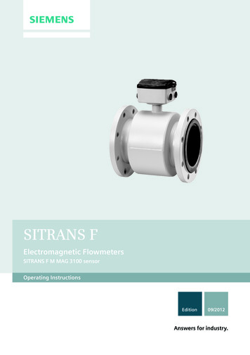
SITRANS FElectromagnetic FlowmetersSITRANS F M MAG 3100 sensorOperating InstructionsEdition09/2012Answers for industry.
SITRANS F M MAG 3100 sensor 1Introduction2Safety notesSITRANS FElectromagnetic FlowmetersSITRANS F M MAG 3100 Service and maintenanceOperating Instructions7Troubleshooting/FAQs8Technical data9Spare parts/AccessoriesAFactory settingsFlange mating dimensonsB(metric)CCoil resistanceElectromagnetic flow sensor for use with transmittertypes SITRANS F M MAG 5000 / 6000 and MAG6000 I09/2012A5E03005599-02
Legal informationWarning notice systemThis manual contains notices you have to observe in order to ensure your personal safety, as well as to preventdamage to property. The notices referring to your personal safety are highlighted in the manual by a safety alertsymbol, notices referring only to property damage have no safety alert symbol. These notices shown below aregraded according to the degree of danger.DANGERindicates that death or severe personal injury will result if proper precautions are not taken.WARNINGindicates that death or severe personal injury may result if proper precautions are not taken.CAUTIONindicates that minor personal injury can result if proper precautions are not taken.NOTICEindicates that property damage can result if proper precautions are not taken.If more than one degree of danger is present, the warning notice representing the highest degree of danger willbe used. A notice warning of injury to persons with a safety alert symbol may also include a warning relating toproperty damage.Qualified PersonnelThe product/system described in this documentation may be operated only by personnel qualified for the specifictask in accordance with the relevant documentation, in particular its warning notices and safety instructions.Qualified personnel are those who, based on their training and experience, are capable of identifying risks andavoiding potential hazards when working with these products/systems.Proper use of Siemens productsNote the following:WARNINGSiemens products may only be used for the applications described in the catalog and in the relevant technicaldocumentation. If products and components from other manufacturers are used, these must be recommendedor approved by Siemens. Proper transport, storage, installation, assembly, commissioning, operation andmaintenance are required to ensure that the products operate safely and without any problems. The permissibleambient conditions must be complied with. The information in the relevant documentation must be observed.TrademarksAll names identified by are registered trademarks of Siemens AG. The remaining trademarks in this publicationmay be trademarks whose use by third parties for their own purposes could violate the rights of the owner.Disclaimer of LiabilityWe have reviewed the contents of this publication to ensure consistency with the hardware and softwaredescribed. Since variance cannot be precluded entirely, we cannot guarantee full consistency. However, theinformation in this publication is reviewed regularly and any necessary corrections are included in subsequenteditions.Siemens AGIndustry SectorPostfach 48 4890026 NÜRNBERGGERMANYOrder number: A5E03005599 08/2012 Technical data subject to changeCopyright Siemens AG 2011.All rights reserved
Table of contents123456Introduction. 51.1Items supplied .51.2History .61.3Further Information .7Safety notes. 92.1Laws and directives .92.2Installation in hazardous area .112.3Certificates .15Description. 173.1System components .173.2Design .183.3Theory of operation.19Installing/Mounting. 214.1Installation safety precautions.214.2Determining a location .214.3Orienting the sensor.244.4Removing the liner protectors .254.5Mounting .274.6Potential equalization.294.7Installation with earthing flanges.30Connecting . 335.1General safety requirements.335.2Remote installation .355.3Installation check .375.4Potting .38Service and maintenance . 396.1Maintenance.396.2Recalibration .396.3Transportation/storage.396.4Unit repair.406.5Technical support.40SITRANS F M MAG 3100 sensorOperating Instructions, 09/2012, A5E03005599-023
Table of contents6.6789Return procedures . 41Troubleshooting/FAQs. 437.1Sensor check . 437.2Fluctuating process values. 45Technical data . 478.1Cable data . 548.2Pressure / temperature range . 558.3Process fluid conductivity. 568.4Liner selection . 578.5Electrode selection. 588.6Dimensions and weight . 59Spare parts/Accessories . 659.1Ordering . 65AFactory settings . 67BFlange mating dimensons (metric). 69CCoil resistance . 71Glossary . 73Index. 75SITRANS F M MAG 3100 sensor4Operating Instructions, 09/2012, A5E03005599-02
1IntroductionThese instructions contain all the information you need for using the device.The instructions are aimed at persons mechanically installing the device, connecting itelectrically, configuring the parameters and commissioning it, as well as service andmaintenance engineers.NoteIt is the responsibility of the customer that the instructions and directions provided in theoperating instructions are read, understood, and followed by the relevant personnel beforeinstalling the device.1.1Items supplied SITRANS F M MAG 3100Calibration reportSITRANS F literature CDQuick Start guideInspection1. Check for mechanical damage due to possible improper handling during shipment. Allclaims for damage are to be made promptly to the shipper.2. Make sure the scope of delivery, and the information on the type plate corresponds to theordering informationSITRANS F M MAG 3100 sensorOperating Instructions, 09/2012, A5E03005599-025
Introduction1.2 History6,75 16 ) 0 0 * 2UGHU 1R 0( ;; ;;;;; ;;;;6HULDO 1R 0( ; ;;;;;; ;;;/LQLQJ ;;;;6L]H ;;;; ,6, ;;; ; ;;;;7XEH (OHFWURGHV ;;;; ;;;;;; ;;;;;;;;&DO IDFWRU)OXLG JURXS 3(' [ 5DWLQJ 31;;0 :3 36 DW r& ;;EDU ;;;SVL0 :3 36 DW r& ;;EDU ;;;SVL70 PD[ ;;;& ;;;SVL;;EDU ;;;r)70 PLQ ;;r& ;r)3URFHVV FRQQHFWLRQ HDU RI 0DQXIDFWXUH ;;;; ;;;,QSXW 9 PD[ PD[ ;;L)0 Product label6LHPHQV 6 )ORZ ,QVWUXPHQWV 1RUGERUJ 'HQPDUN0DGH LQ )UDQFH①②③④⑤⑥⑦⑧⑨Fluid groupCalibration factorSize and liner typeSerial NumberMaximum allowable pressureMedia temperatureYear of ManufacturePower supplyOrder NumberFigure 1-1Example of product label6,75 16 ) 0 0 * ([ LD 7HUPLQDOV 8L 9 ,L P 3L : &L Q) /L : 51,1* '2 127 23(1 : (1121 ,175,16,& // 6 )(&,5&8,76 5( (1(5*, ('[[[[ ,, * ')0 Specification label([ G H LD ,,& 7 7 ([ W' ,3 7 r& 3LSH WHPSHUDWXUH . ,3 6LUD 7(; ;6LHPHQV 6 )ORZ ,QVWUXPHQWV 1RUGERUJ 'HQPDUN0DGH LQ )UDQFH①②③Figure 1-21.2Intrinsically safe dataEx approval typeEx approval referenceExample of specification labelHistoryThe contents of these instructions are regularly reviewed and corrections are included insubsequent editions. We welcome all suggestions for improvement.The following table shows the most important changes in the documentation compared toeach previous edition.SITRANS F M MAG 3100 sensor6Operating Instructions, 09/2012, A5E03005599-02
Introduction1.3 Further Information1.3EditionRemarks0106/2010First editionThe Operating Instructions replaces: MAG 3100 part of SITRANS F M HANDBOOK (A5E02435647) MAG 3100 part of SITRANS F M MAG 6000 I Ex d Operating Instructions MAG 3100 part of SITRANS F M MAG 6000 19" & Safety Barrier OperatingInstructions MAG 3100 Instructions MAG 3100 with PTFE and PFA liners Instructions01.112/2011General update02Updated temperature specifications09/2012Updated coil resistance tableUpdated ATEX approvalFurther InformationProduct information on the InternetThe Operating Instructions are available on the CD-ROM shipped with the device, and onthe Internet on the Siemens homepage, where further information on the range of SITRANSF flowmeters may also be found:Product information on the internet (http://www.siemens.com/flow)Worldwide contact personIf you need more information or have particular problems not covered sufficiently by theseOperating Instructions, get in touch with your contact person. You can find contactinformation for your local contact person on the Internet:Local contact person (http://www.automation.siemens.com/partner)SITRANS F M MAG 3100 sensorOperating Instructions, 09/2012, A5E03005599-027
Introduction1.3 Further InformationSITRANS F M MAG 3100 sensor8Operating Instructions, 09/2012, A5E03005599-02
2Safety notesCAUTIONCorrect, reliable operation of the product requires proper transport, storage, positioning andassembly as well as careful operation and maintenance. Only qualified personnel shouldinstall or operate this instrument.NoteAlterations to the product, including opening or improper repairs of the product, are notpermitted.If this requirement is not observed, the CE mark and the manufacturer's warranty will expire.2.1Laws and directivesGeneral requirementsInstallation of the equipment must comply with national regulations.Instrument safety standardsThe device has been tested at the factory, based on the safety requirements. In order tomaintain this condition over the expected life of the device the requirements described inthese Operating Instructions must be observed.NOTICEMaterial compatibilitySiemens Flow Instruments can provide assistance with the selection of wetted sensorparts. However, the full responsibility for the selection rests with the customer and SiemensFlow Instruments can take no responsibility for any failure due to material incompatibility.CE marked equipmentThe CE-mark symbolizes the compliance of the device with the following guidelines: EMC Directive 2004/108/EC Low Voltage Directive (LVD) 2006/95/EC Pressure Equipment Directive (PED/DGRL) 93/23/EGSITRANS F M MAG 3100 sensorOperating Instructions, 09/2012, A5E03005599-029
Safety notes2.1 Laws and directives ATEX Directive 94/9/EC MID Directive 2004/22/ECCompliance with PED directive"Pressure Equipment Directive" (PED) is mandatory for all pressure equipment sold withinthe EU and EFTA.Siemens Flow Instruments products complies to PED as stated in the following table.Table 2- 1MAG 3100 PED ComplianceFlangemmPN 6PN 10PN 16PN25PN 40PN 63PN 100150 lb300 N/AN/AN/ASITRANS F M MAG 3100 sensor10Operating Instructions, 09/2012, A5E03005599-02
Safety notes2.2 Installation in hazardous areaTable 2- 2PED table keySEPExcluded from PED under SEP (Sound Engineering Practice)PEDProduct covered by PED and only available as fully PED-conformingPED*Product covered by PED but available as either conforming or non-conforming toPEDN/ASize/pressure outside of PED scope or not available in the size rangeN/A*DN1400-2000 only available non conforming to PEDCAUTIONAll products sold outside of EU and EFTA are excluded from the Pressure Equipmentdirective, also products sold into certain market sectors are excluded. These include1. Meters used in networks for the supply, distribution and discharge of water.2. Meters used in pipelines for the conveyance of any fluid from offshore to onshore.3. Meters used in the extraction of petroleum or gas, including christmas tree and manifoldequipment.4. Any meter mounted on a ship or mobile offshore platform.2.2Installation in hazardous areaWARNINGEquipment used in hazardous areas must be Ex-approved and marked accordingly.It is required that the special conditions for safe use provided in the manual and in the Excertificate are followed!Hazardous area approvalsThe device is approved for use in hazardous area and has the following approvals:MAG 3100 Ex DN 350-2000: Ex e ia IIC T3-T6 Gb Ex tD A21 IP67 T* C (* pipe temperature 5 K) (remote mounted) Ex d e [ia] ia IIC T3-T6 Gb Ex tD A21 IP67 T** C (** pipe temperature 5 K, but not lessthan 85 C) (compact mounted)MAG 3100 Ex DN 15-300: Ex de ia IIC T3-T6 Gb Ex tD A21 IP67 T* C (* pipe temperature 13 K) (remote mounted) Ex de* [ia] [ib] ia ib* IIC T3-T6 Gb Ex tD A21 IP67 T** C (** pipe temperature 13 K, butnot less than 85 C) (compact mounted)* The "e" and "ib" markings on the compact version are only applicable if the "Ex e"supply/data terminal chamber option is used.SITRANS F M MAG 3100 sensorOperating Instructions, 09/2012, A5E03005599-0211
Safety notes2.2 Installation in hazardous areaWARNINGMake sure the hazardous area approval is suitable for the environment in which the devicewill be installed.WARNINGAll approvals are based on non-flammable processes only!Intrinsically safe dataTable 2- 3Intrinsically safe data for MAG 3100 Ex remote mountedElectrode circuit "ia" (Terminal 82,83)Ui30VLi2μHIi50mAPi0.5WCi50nFCoil circuit "Ex e" (Terminal 85,86)Ui30 V (70 V peak)Ii130mAWARNINGCompact mounted versionsFor intrinsically safe data for MAG 3100 Ex compact mounted with MAG 6000 I Ex d, referto the Operating Instructions of MAG 6000 I or to certificate number Sira 11ATEX2124X,available here: Certificates tificates).WARNINGWith intrinsically safe circuits, use only certified meters appropriate for the transmitter.If a non-conforming supply unit is used, the "fail-safe" type of protection will no longer beeffective and the approval certification will be invalid.SITRANS F M MAG 3100 sensor12Operating Instructions, 09/2012, A5E03005599-02
Safety notes2.2 Installation in hazardous areaTemperature specifications for Ex useTable 2- 4Temperature classifications for MAG 3100 Ex (remote or compact with MAG 6000 I)Maximum process fluid temperature Temperature[ C]classAmbient temperature [ C]75T6 (85 C)-25 . 6090T5 (100 C)-25 . 60125T4 (135 C)-25 . 60180 (Remote configuration)T3 (200 C)-25 . 60150 (Compact configuration)T3 (200 C)-25 . 50For dust protection, the surface temperature is equal to the process fluid temperature plus 5 CSpecial conditions for safe useIt is required that: Electrical connections are in accordance with national requirements. Appropriate cable connectors are used for the output circuits:– Intrinsically safe: blue– Non-intrinsically safe: black Minimum 4 mm2 cable is to be used for potential equalization Cable glands for coil circuit must be Ex e approved (increased safety) and fit theapplication by being approved for the cable used as regards size and temperature. Sensor insulation thickness is max. 100mm (only insulated sensors). IEC/EN 61241-14 and 61241-17 are considered for installation in areas with combustibledust.SITRANS F M MAG 3100 sensorOperating Instructions, 09/2012, A5E03005599-0213
Safety notes2.2 Installation in hazardous areaWARNINGPotential equalizationIn operation, the output is earthed through the conductive medium being measured andtherefore potential equalisation is necessary throughout the hazardous area.The apparatus housing shall be connected to the potential equalising conductor in thehazardous area.WARNINGExternal connections to Ex e terminalsThe external connections to the Ex 'e' Terminals of the Remote version shall complywith the following: The wire conductors shall have a cross-sectional area between 0.5 mm2 and 2.5mm2. No more than one single or multiple strand wire conductor shall normally beconnected to each of the terminals. If multiple conductors are required, these shall bejoined in a suitable manner, e.g. two conductors into a single insulated crimped bootlace ferrule. The insulation on the wire conductors shall extend to within 1mm of the metal of theterminal throat. The terminal screws shall be tightened down with a torque between 0.5 Nm and 0.7Nm. The terminals shall never be exposed to temperatures outside of the range -50 C to 130 C; in addition, they shall only be installed and wired with cable in an ambienttemperature of -10 to 80 C. Furthermore, in the event of there being a processtemperatures of 180 C in conjunction with an upper ambient temperature of 50 Cthe terminal strips should not be installed or wired with cable.WARNINGExplosive gas or dustThe terminal box shall not be opened when an explosive gas or dust atmosphere maybe present.WARNINGDo NOT open the device while energized; otherwise there is a risk of explosion.WARNINGLaying of cablesCable for use in zone 1 and 2 or 21 and 22 must satisfy the requirements for having aproof voltage AC 500 V applied between the conductor/ground, conductor/shield andshield/ground.Connect the devices that are operated in hazardous areas as per the stipulationsapplicable in the country of operation, e.g. for Ex "d" and "nA", permanent cables mustbe laid.SITRANS F M MAG 3100 sensor14Operating Instructions, 09/2012, A5E03005599-02
Safety notes2.3 Certificates2.3CertificatesCertificates are posted on the Internet and on the documentation CD-ROM shipped with thedevice.See alsoCertificates tificates)SITRANS F M MAG 3100 sensorOperating Instructions, 09/2012, A5E03005599-0215
Safety notes2.3 CertificatesSITRANS F M MAG 3100 sensor16Operating Instructions, 09/2012, A5E03005599-02
Description3The main applications of the SITRANS F M electromagnetic flow sensors can be found in thefollowing fields: Process industry Chemical industry Steel industry Mining Utility Power generation & distribution Oil & gas / HPI Water & waste water Pulp & paper3.1System componentsThe SITRANS F M flowmeter system includes: Transmitter (types: SITRANS F M MAG 5000/6000 or MAG 6000 I) Sensor (types: SITRANS F M MAG 1100/1100 F, MAG 3100/3100 P or MAG 5100 W) Communication module (optional) (types: HART, PROFIBUS PA/DP, MODBUS RTU RS485, Foundation Fieldbus H1, Devicenet) SENSORPROM memory unitCommunication solutionsThe SITRANS F M range of add on modules, presently including HART, FoundationFieldbus. MODBUS RTU RS 485, PROFIBUS PA / DP and Devicenet, are all applicable withthe SITRANS F M MAG 6000 transmitter.SITRANS F M MAG 3100 sensorOperating Instructions, 09/2012, A5E03005599-0217
Description3.2 Design3.2DesignSITRANS F M MAG 3100 is available in a wide range of sizes (DN 15 to DN 2000 (½" to78")) and pressure ratings (PN 6 to PN 100 / ANSI Class 150 / 300, AS 2129 / AS 4087. Onrequest up to 690 bar (10 000 psi)) The fully welded construction provides a ruggedness thatsuits the toughest applications and environments.Sensor housing and flanges are designed in carbon steel (ASTM A 105) and terminal box infibre glass reinforced polyamide or optionally in stainless steel (AISI 316). Measuring pipe ismade of stainless steel (AISI 304) while liners and electrodes are available in variousmaterial, which makes the sensor highly resistant to a wide range of chemicals.The present range of liner types includes: PTFE PFA Soft rubber EPDM Linatex Ebonite Hard RubberElectrodes are available in: Hastelloy C276 or C22 AISI 316Ti (1.4571) Platinum / Iridium Titanium TantalumThe sensors carry a wide range of approvals, see Technical data (Page 47).SITRANS F M MAG 3100 sensor18Operating Instructions, 09/2012, A5E03005599-02
Description3.3 Theory of operation3.3Theory of operationThe flow measuring principle is based on Faraday’s law of electromagnetic induction.0DJQHWLF )LHOG)ORZUi When an electrical conductor of length L is moved at velocity v, perpendicular to thelines of flux through a magnetic field of strength B, the voltage Ui is induced at the ends ofthe conductorUi L x B x v Ui Induced voltage L Conductor length Inner pipe diameter k1 B Magnetic field strength k2 v Velocity of conductor (media) k k 1 x k2Ui k x v, the electrode signal is directly proportional to the fluid velocityOperating principleThe coil current module generates a pulsating magnetizing current that drives the coils in thesensor. The current is permanently monitored and corrected. Errors or cable faults areregistered by the self-monitoring circuit.The input circuit amplifies the flow-proportional induced voltage signal from the electrodes.The input impedance is extremely high: 1014 Ω which allows flow measurements on fluidswith conductivities as low as 5 µS/cm. Measuring errors due to cable capacitance areeliminated due to active cable screening.The digital signal processor converts the analog flow signal to a digital signal andsuppresses electrode noise through a digital filter. Inaccuracies in the transmitter as a resultof long-term drift and temperature drift are monitored and continuously compensated for viathe self-monitoring circuit. The analog to digital conversion takes place in an ultra low noiseASIC with 23 bit signal resolution. This has eliminated the need for range switching. Thedynamic range of the transmitter is therefore unsurpassed with a turn down ratio of minimum3000:1.SITRANS F M MAG 3100 sensorOperating Instructions, 09/2012, A5E03005599-0219
Description3.3 Theory of operationSITRANS F M MAG 3100 sensor20Operating Instructions, 09/2012, A5E03005599-02
Installing/Mounting4SITRANS F flowmeters with minimum IP65/NEMA 4X enclosure rating are suitable for indoorand outdoor installations. Make sure that pressure and temperature specifications indicated on the devicenameplate / label will not be exceeded.WARNINGInstallation in hazardous locationSpecial requirements apply to the location and interconnection of sensor and transmitter.See "Installation in hazardous area" (Page 11)4.1Installation safety precautionsWARNINGHigh pressure hazardIn applications with working pressures/media that can be dangerous to people,surroundings, equipment or others in case of pipe fracture, we recommend that specialprecautions such as special placement, shielding or installation of a pressure guard or asafety valve are taken when the sensor is mounted.4.2Determining a locationNoteThe sensor must always be completely filled with liquid.Figure 4-1Correct installation with filled pipesSITRANS F M MAG 3100 sensorOperating Instructions, 09/2012, A5E03005599-0221
Installing/Mounting4.2 Determining a location Avoid the following installations– Installation at the highest point in the pipe system– Installation in vertical pipes with free outlet– Wrong installation at high pointFigure 4-2Correct installation at low point before outletInlet and outlet conditionsTo achieve accurate flow measurement it is essential to have straight lengths of inlet andoutlet pipes and a certain distance to pumps and valves.It is also important to centre the flowmeter in relation to pipe flanges and gaskets.SITRANS F M MAG 3100 sensor22Operating Instructions, 09/2012, A5E03005599-02
Installing/Mounting4.2 Determining a locationInstallation in large pipesThe flowmeter can be installed between two reducers (e.g. DIN 28545). At 8 the followingpressure drop curves apply. The curves are applicable to water.SITRANS F M MAG 3100 sensorOperating Instructions, 09/2012, A5E03005599-0223
Installing/Mounting4.3 Orienting the sensorExample:A flow of 3 m/s (V) in a sensor with a diameter reduction from DN 100 to DN
SITRANS F M MAG 3100 sensor Operating Instructions, 09/2012, A5E03005599-02 7 Edition Remarks 01 06/2010 First edition The Operating Instructions replaces: MAG 3100 part of SITRANS F M HANDBOOK (A5E02435647) MAG 3100 part of SITRANS F M MAG 6000 I Ex d Operating Instructions