Transcription
Ultrasonic flowmetersSITRANS FUG1010 IP65 NEMA 4XInstruction Manual - September 2008SITRANS F
IMPORTANT NOTICEControlotron is now part of:Siemens Energy & Automation, Inc.Process Instrumentation Business Unit (PI BU)CoC Ultrasonic FlowSITRANS FUG 1010GCN/GCDNCLAMP-ON MUTI-FUNCTIONGAS FLOWMETERThis equipment contains components that aresusceptible to electrostatic discharge (ESD).Please observe ESD control measures duringthe handling and connection process.Field Manual CQO:1010GCNFM-3September 2007For use with Operating SystemSoftware Version 3.01.05E or laterPrepared ByDateReviewed ByDateCopyright 2007 Siemens Energy & Automation, Inc. All Rights ReservedMade in the USAPrinted September 2007
Manual ChangesNOTE: For the latest updates and revisions to this field manual go to:http://support.automation.siemens.com/ and check the Product Manual listing.
Errata1010FMA-46ERRATADigital Pgen Function and Wiring Procedure UpdateNOTE: The following applies to System 1010GN, 1010GCN and 1010GCSN Gas Flowmeter installation manuals.Replace the PGEN menu cell description and set up procedure in the Data Span/Set/Cal menu Span Dataoption list including any related menu graphics and text throughout the manual with the following:PGENThe [PGEN P/Unit Volume] menu cell entry controls a digital output pulse function and is available inCustody Transfer units only (designated by a “C” or “U” in their part number). It allows the assigning ofPGEN digital signal pulses per unit of volume. For example, 1000 output pulses per cubic foot of gas.The default PGEN value is configured to provide a 5000 Hz output frequency at a flow velocity of 100 ft/sec (30 meters/sec).NOTE: The unit of volume is determined by the Volume Units initially selected from the [TotalVolume Units] menu cell option list.1010GUDN,1010GCCDN, 1010GCSCDN(Expanded 1010N-7 I/O Module)Installation Drawing 1010N-7-7 (Sheet 3 of 3)(Ultra Performance NPRIMARY FREQUENCY OUTPUT / OPEN COLLECTORPRIMARY FREQUENCY OUTPUT / TTLQUADRATURE FREQUENCY OUTPUT / OPEN COLLECTORQUADRATURE FREQUENCY OUTPUT / TTLNOTESDigitally SynthesizedPulse Waveform(continued on next page)E-1
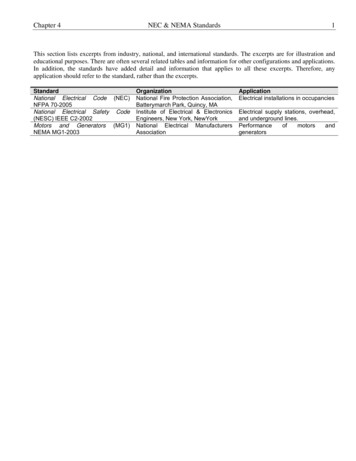
Errata1010FMA-46PGEN Wiring DiagramThe unit must be wired as shown below before assigning PGEN output pulses.1010N-1MAIN BOARD1010N-7K, -7K2 OR -7K3I/O CONNECTION BOARD 5VPG4524TTL/CMOS3DPGEN 2-Ø2TTL PGEN SIGNALTB2-12 DPGEN 2-Ø2TTL LOGICQUADRATURE PHASETO END USEREQUIPMENTTB2-4 GND[VO2-]GROUNDPG32OC PGEN SIGNAL13DPGEN 1-Ø2SEE TABLETB2-11 DPGEN 1-Ø2OPEN COLLECTORQUADRATURE PHASEGROUNDTB2-4 GND[VO2-]5-36VDC, 15-20mANOMINAL CURRENTCONSUMPTIONTO END USEREQUIPMENT 5VPG25243DPGEN 2-Ø1TTL/CMOSTTL PGEN SIGNALTB2-10 DPGEN 2-Ø1TTL LOGICREFERENCE PHASETO END USEREQUIPMENTTB2-2 GND[VO1-]GROUND2PG1OC PGEN SIGNAL13DPGEN 1-Ø1SEE TABLETB2-09 DPGEN 1-Ø1OPEN COLLECTORREFERENCE PHASEGROUNDTB2-2 GND[VO1-]5-36VDC, 15-20mANOMINAL CURRENTCONSUMPTIONTO END USEREQUIPMENTNOTES2: TB2-10 & TB2-12 are TTL/CMOS compatible outputs.No pullup resistor is required.CAUTION: Application of any external voltage, evenvia a resistor, could permanently damage this circuit.1. TB2-9 & TB2-11 are Open Collector Outputs thatrequire external pull up resistors for operation.See table on next page for External Supply Voltageand suggested resistor value and ratings.Maximum current into the transistor is 100mA.Maximum Voltage is 36Vdc.CAUTION: Negative voltages with respect ground willpermanently damage the transistors.1010N-7K, -7K2 or 7K3 I/O MODULES WITH ULTRA PRECISION FLOWMETERSOPEN COLLECTOR USER RESISTOR RECOMMENDATIONSUSER SUPPLYVOLTAGE[Vdc]591218242836EXTERNALR1 OR R2[Ohms]2705106801000150018002400EXPECTEDCURRENT OR WATTAGE[WATTS]1/21/21/23/411-1/41-1/4
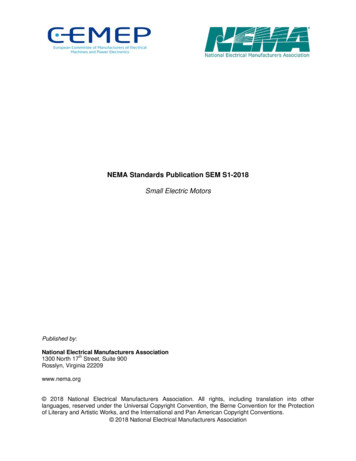
Errata1010FMA-46FOR POSITIVE FLOWPG3 and PG4 LAGS PG1 and PG2 by 90ºREFERENCEPG1 or PG2QUADRATURE LAGSFOR POSITIVE FLOWPG3 or PG4FOR NEGATIVE FLOWPG3 and PG4 LEADS PG1 and PG2 by 90ºREFERENCEPG1 or PG2QUADRATURE LEADSFOR NEGATIVE FLOWPG3 or PG4To change the default PGEN settings:From the [Span Data] menu pressFrom the [PGEN P/Unit Volume] menu cell, pressto activate the numeric entry.Use the numeric keys to enter the desired number of PGEN pulses per unit volume.NOTE: Ensure that the number entered will provide sufficient resolution while remaining withinthe 20 Hz to 5000 Hz pulse frequency range. Note that the PGEN output will stop sending pulses at flow rates corresponding to frequencies less than 20 Hz. In this case thePGEN value must be increased.To store the data pressENTE-3
1010FMA-56MANUALADDENDUMOperating System SoftwareVersion UpdateManual AddendumSeptember 2008Copyright 2008 Siemens Energy & Automation, Inc. All rights reservedMade in the USA
1010FMA-56Manual AddendumOperating System Software Version UpdateINTRODUCTIONThe following software operating system version update is for Version 3 flowmeters. Please refer tothis addendum when using this technical manual with Version 3 operating system software andflowmeters that have been updated to Version 5.Operating System Software Changes1. The [Meter Type Menu] includes a [Language] menu item that allows the selection of multiple flowmetermenu foreign languages.2. Version 3 and Version 5 Operating System DifferencesThe following table lists the differences between Version 3 and Version 5 operating system menuitems and menu hint lines.Version 3Select Pipe ClassPick/Install XdcrData/Span/Set/CaStrip Chart SetupDual Channel FlowDual Beam FlowDatalogger SetupTemperature RangePipe ConfigurationDatalogger SetupDatalogger ModeDatalogger DataLog Time IntervalDisplay DataloggerRecall Site SetupDelete Site SetupInstall Completed?Estimated Vs m/sChannel /Path SetupReflexor Zero Fault/SetMemory Delay (sec)Flow Volume UnitsFlow Display RangeFlow Display ScaleTotal Volume UnitsBatch/Sample TotalCalibrate FlowrateAnalog Input SetupFlow Vel F/SVs m/sValc %Vaer %Vs Max m/sVersion 5Pick Pipe ClassInstall XdcrSpan/Set/CalDisplay Setup2 Channel FlowDual Path FlowLogger SetupTemp RangePipe ConfigLogger SetupLogger ModeLogger DataLogger IntervalDisplay LoggerRecall SiteDelete SiteInstall CompleteEstimated Vs M/SChannel SetupZero Fault/SetMemory Delay s)Flow Vol. UnitsFlow Disp. RangeFlow Disp. ScaleTotal Vol. UnitsBatch/Sample TotCalib. FlowrateAnalog Inp SetupVelocity F/SVs M/SValcVaerVs Max M/S(continued )A-1
1010FMA-56Manual AddendumVersion 3Vs Min m/sChannel/Path SetupVfmax GAL/MINDate Site Created:Empty %Analog Output TrimPick flowtube size and typeVersion 5Vs Min M/SChan/Path SetupVfmaxSite Created:EmptyAnalog Out TrimSelect flowtubeand start operationEmpty Pipe SetEmpty Flowtube SetGas Flowmeter Flow and VoS Unit Changes1. Flowmeter TypesFlowmeter configurations included with this change include all SITRANS F Gas Flowmeters (7ME361*).2. Flow UnitsThe table below describes the translation from the current gas flow units to the new gas flow units,where only Cubic Feet and Cubic Meter volume units are affected. Also note that M thousands andMM millions. Mass units and Velocity units remain unchanged.Note: The flow legend changes depending upon the selection of Standard Volume enabled ordisabled.For STD VOLUME disabledVersion 3Version 5CU FT/SECACFSCU FT/MINACFMCU FT/HRACFHCU FT/DAYACFDKCU FT/SECMACFSKCU FT/MINMACFMKCU FT/HRMACFHKCU FT/DAYMACFDMCU FT/SECMMACFSMCU FT/MINMMACFMMCU FT/HRMMACFHMCU FT/DAYMMACFDCU M/SECCU M/MINCU M/HRCU M/DAYKCU M/SECKCU M/MINKCU M/HRKCU M/DAYMCU M/SECMCU M/MINMCU M/HRMCU M/DAYM3/secM3/minM3/hrM3/dayE3 M3/secE3 M3/minE3 M3/hrE3 M3/dayE6 M3/secE6 M3/minE6 M3/hrE6 M3/dayFLOW UNITSFor STD VOLUME enabledVersion 3Version 5CU FT/SECSCFSCU FT/MINSCFMCU FT/HRSCFHCU FT/DAYSCFDKCU FT/SECMSCFSKCU FT/MINMSCFMKCU FT/HRMSCFHKCU FT/DAYMSCFDMCU FT/SECMMSCFSMCU FT/MINMMSCFMMCU FT/HRMMSCFHMCU FT/DAYMMSCFDM/SECCU M/MINCU M/HRCU M/DAYKCU M/SECKCU M/MINKCU M/HRKCU M/DAYMCU M/SECMCU M/MINMCU M/HRMCU M/DAYA-2NM3/secNM3/minNM3/hrNM3/dayE3 NM3/secE3 NM3/minE3 NM3/hrE3 NM3/dayE6 NM3/secE6 NM3/minE6 NM3/hrE6 NM3/day
1010FMA-56Manual Addendum3. Total UnitsTotal units are similar to flow units.TOTALIZE UNITSFor STD VOLUME disabledVersion 3CU FTKCU FTMCU FTCUMKCU MMCU MVersion 5ACFMACFMMACFM3E3 M3E6 M3TOTALIZE UNITSFor STD VOLUME enabledVersion 3CU FTKCU FTMCU FTCUMKCU MMCU MVersion 5SCFMSCFMMSCFNM3E3 NM3E6 NM34. Sound Velocity UnitsSound velocity will continue to be reported in units of meters/sec for metric units but will change toFeet/sec for English unit selection. The flowmeter will display M/S and F/S to represent these twovariations.Note: The units for Sound Velocity will be based on the [Preferred Units] menu item found inthe [Meter Facilities] menu and can not be changed unless a new site is created.5. Transducer Model Menu NameThe following table lists the operating system menu item differences between Version 3 Hi Precisionand Version 5 Hi Precision transducer model names that appear on the [Install Xdcr] menu. Note thatT1, T2 and T3 indicate the different temperature ranges of the transducer.Version 3 TransducersHi Precision1011HG Hi Prec.Version 5 TransducersHi Precision1011HP-T11011HP-T21011HP-T3A-3
1010FMA-57MANUALADDENDUMDigital P-GenApplicationsProcedure UpdateManual AddendumSeptember 2008Copyright 2008 Siemens Energy & Automation, Inc. All rights reservedMade in the USA
1010FMA-57Manual AddendumDigital P-Gen Applications Procedure UpdateINTRODUCTIONThe following Digital P-Gen applications procedure is to be added to the Data Span/Set/Cal Menusection of the SITRANS liquid and gas flowmeter manuals listed below:Gas Flowmeter ManualsFUG1010 IP 65 (NEMA 4X) Clamp-On Gas Flowmeter manual (CQO:1010GCNFM-3)FUG1010 IP 65 (NEMA 7) Compact Clamp-On Gas Flowmeter manual (CQO:1010GCXFM-3)FUG1010 IP 65 (NEMA 7) Compact Insert Gas Flowmeter manual (CQO:1010GXFM-3)Liquid Flowmeter ManualsFUH1010 IP 65 (NEMA 4X) Clamp-On Flowmeter manual (CQO:1010DVNFM-3)FUH1010 IP 65 (NEMA 4X) Clamp-On Flowmeter manual (CQO:1010PVNFM-3)FUH1010 IP 65 (NEMA 7) Compact Clamp-On Flowmeter manual (CQO:1010DVXFM-3)FUH1010 IP 65 (NEMA 7) Compact Clamp-On Flowmeter manual (CQO:1010PVXFM-3)DIGITAL P-GEN APPLICATIONS PROCEDUREAdjusting the PGEN OutputThe default setting for the Digital PGEN output provides a 5000 Hz frequency at an assumed maximumvelocity of 100 ft/sec. In certain cases it may be necessary to change this default PGEN value. Forexample:zIf the PGEN signal cable is very long, then the added cable capacitance may prevent reliable RTUpulse detection at or near 5000 Hz. In this case it may be necessary to decrease the PGEN (Pulses/ Unit Volume) setting using the equation below.Pulses / UnitVolumeMaxFreqMaxFlowWhere: MaxFreq Maximum desired frequency (Hz)MaxFlow Maximum flow rate (Unit Volume / second)zFor very low operating flow rates, the pulse frequency may approach the 20 Hz limit of the PGENoutput. In this case it may be necessary to increase the PGEN (Pulses / Unit Volume) setting.Pulses / UnitVolumeMinFreqMinFlowWhere: MinFreq Minimum desired frequency (Hz). Must be greater than 20 Hz!MinFlow Minimum operating flow rate (Unit Volume / second)Note: If STD VOL is selected then the “unit volume” for PGEN will represent Standard Volume,not actual volume.Forcing the PGEN Output FrequencyTo test the operation of the flowmeter with an RTU, or other pulse counting device, it may be necessaryto force the PGEN output frequency, especially when the pipeline is not flowing during flowmetercommissioning. This can be accomplished by setting the AnCal diagnostic value to a flow ratecorresponding to the desired frequency output. (Refer to the appropriate paragraph in your manual foroperation of the AnCal function.)A-1
1010FMA-57Manual AddendumThe example below demostrates how to calculate the AnCal flow rate based on the desired pulse outputfrequency and the entered PGEN (Pulses / Unit volume) setting:For PGEN setting 53 Pulses /CU FT and a desired frequency 1000 Hz1. Temporarily change flow rate units to CU FT / SEC (Use same volume units as Totalizer.)2. Set AnCal 1000 / 53 18.868 CU FT / SEC3. 1000 Hz frequency should now be observed on the PGEN output.A-2
1010FMA-58MANUALADDENDUMDigital DampingProcedure UpdateFor Gas & LiquidFlowmetersManual AddendumSeptember 2008Copyright 2008 Siemens Energy & Automation, Inc. All rights reservedMade in the USA
1010FMA-58Manual AddendumDigital Damping Procedure Update for Gas & Liquid FlowmetersINTRODUCTIONThe following Digital Damping procedure updates are for SITRANS F gas and liquid clamp-onflowmeters.Replace the Digital Damping Control: (Hot Key 1 and 2) procedure in the “Detection Modes”section (sub-paragraph: Command Modes) in the appropriate gas and liquid STIRANS F flowmetermanuals.FUG1010 Gas Clamp-on Flowmeter ManualsDigital Damping Control: (Hot Key 1 and 2)The FUG1010 permits user modification of the digital averaging used by the signal processing routines.In general, the default damping values selected by the FUG1010 will provide optimal performance overa wide range of transit time applications. However, in extreme cases of unstable flow, pulsating flow,low signal levels or high electronic noise it may be necessary to override these default settings topermit uninterrupted and reliable flow measurement.Test Facilities Graph ScreenThe FUG1010 Graph Screen includes the capability to access a set of command codes, which enablea user to override a number of default meter settings. The most important parameter is the digitaldamping control, which can be accessed by pressing number 1 or 2 on the keypad while in theSignal Graph Screen mode.[MinDamp] CommandPressing the 1 key will cause [MinDamp #] to appear on the command line at the lower left-handcorner of the screen. The number listed to the right of the command code represents the exponent inthe FUG1010 exponential averaging routine, where the larger the number the greater the digital averaging.Pressing the key will increase the damping value. Likewise, pressing the - key will decreasethe damping value. To exit this mode, press the 0 key on the keypad.[MaxDamp] CommandPressing the 2 key will bring up the [MaxDamp] command. The function of this parameter is similarto the [MinDamp] command described above; however, the two parameters interact in the followingmanner. The MinDamp value must not exceed the MaxDamp value, therefore increasing the MinDampvalue above the previous MaxDamp value will set both parameters to the same value. In most cases,it is preferred that both damping parameters be set to the same value, however, in cases where rapidresponse to changes in gas sound velocity for flow rate is required, the two values may be set differently.In this situation the meter will use the MaxDamp value when conditions are stable, but then switch toa faster damping value (limited by MinDamp) when a significant change in sound velocity or flow rateis perceived. To exit this mode, press the 0 key on the keypad.A-1
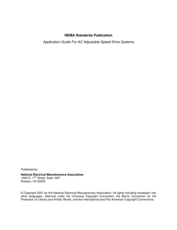
1010FMA-58Manual AddendumTo access the Digital Damping Control using the Test Facilities Graph Screen, proceed as follows:1. To use the Test Facilities Graph Screen you must have a working site.2. To activate the Test Facilities Graph Screen:zzzIn the main menu, scroll to the [Diagnostic Data] menu and select [Test Facilities].Scroll down to [Graph], press the Right Arrow and highlight [Yes]. Press ENT to select.The Test Facilities Graphic Screen will appear on the meter display as shown below.Setting the Digital Damping Factor to a value HIGHER than the default value of 4 may be necessaryin cases where the signal to noise ratio (SN) is found to be unacceptably low ( 15:1), but only if thenoise is determined to be asynchronous (i.e., not associated with the transmit or flowmeter timingcircuitry) as shown in the signal example above, where the baseline noise has a higher frequencythan the true gas signal.The following application conditions may require a higher Digital Damping Factor:zzzClose proximity to pressure control valves which may generate in-band acoustic noiseVery low acoustic signal levels (ALC 40%)High electronic noise from variable frequency drives or other external equipment.A-2
1010FMA-58Manual AddendumTo INCREASE the Digital Damping:1. Press the 1 key while viewing the Test Facilities Graph Screen as shown above. The dampingcontrol [MinDamp #] should appear on the command line at the lower left-hand corner of thescreen.Note: The number listed to the right of the command code on the screen represents theexponent in the exponential averaging routine, where the larger the number representsthe greater the digital averaging. Setting this exponent higher than 7 is generally notrecommended.2, Pressing the key will increase the MinDamp Factor by one unit for each key press. To exit thismode, press the 0 key on the keypad.The above example shows that increasing the Digital Damping reduces asynchronous noise.Setting the Digital Damping factor to a value LOWER than the default value of 4 may be justified incases where pulsating flow is present (such as from a reciprocating compressor) or for the purposeof diagnosing transient signal behavior. A pulsating flow condition that generates more than /- 45degrees of phase jitter will generally cause signal correlation problems when any digital averaging isused. In this case it may be necessary to completely eliminate the digital averaging by reducing theDigital Damping Factor to 0. In such a case it may also be necessary to install a narrow band tunedamplifier (Input Module) if too much asynchronous noise exists.To DECREASE the Digital Damping:1. Press the 2 key while viewing the Test Facilities Graph Screen. The damping control [MaxDamp#] should appear on the command line at the lower left-hand corner of the screen.2. Pressing the - key will decrease the MaxDamp Factor by one unit for each key press. To exit thismode, press the 0 key on the keypad.A-3
1010FMA-58Manual AddendumLiquid Clamp-on Flowmeter ManualsReplace the Digital Damping Control: (Hot Key 1 and 2) procedure in the “Detection Modes” section(sub-paragraph: Command Modes) in the following flowmeter manuals:FUS1010 IP 65 (NEMA 4X) Clamp-On Flowmeter manual (CQO:1010NFM-3)FUE1010 IP 65 (NEMA 4X) Clamp-On Flowmeter manual (CQO:1010ENFM-3)FUH1010 IP 65 (NEMA 4X) Clamp-On Flowmeter manual (CQO:1010DVNFM-3)FUH1010 IP 65 (NEMA 4X) Clamp-On Flowmeter manual (CQO:1010PVNFM-3)FUP1010 IP 40 (NEMA 1) Clamp-On Portable Flowmeter manual (CQO:1010PFM-3)FUE1010 IP 40 (NEMA 1) Clamp-On Portable Flowmeter manual (CQO:1010EPFM-3)Digital Damping Control: (Hot Key 1 and 2)The meter permits user modification of the digital averaging used by the signal processing routines. Ingeneral, the default damping values selected by the METER will provide optimal performance over awide range of transit time applications. However, in extreme cases of unstable flow, pulsating flow, lowsignal levels or high electronic noise it may be necessary to override these default settings to permituninterrupted and reliable flow measurement.Test Facilities Graph ScreenThe Graph Screen includes the capability to access a set of command codes, which enable a user tooverride a number of default meter settings. The most important parameter is the digital dampingcontrol, which can be accessed by pressing number 1 or 2 on the keypad while in the SignalGraph Screen mode.[MinDamp] CommandPressing the 1 key will cause [MinDamp #] to appear on the command line at the lower left-handcorner of the screen. The number listed to the right of the command code represents the exponent inthe meter exponential averaging routine, where the larger the number the greater the digital averaging.Pressing the key will increase the damping value. Likewise, pressing the - key will decreasethe damping value. To exit this mode, press the 0 key on the keypad.[MaxDamp] CommandPressing the 2 key will br
Ultrasonic flowmeters SITRANS FUG1010 IP65 NEMA 4X Instruction Manual - September 2008 . Controlotron is now part of: Siemens Energy & Automation, Inc. Process Instrumentation Business Unit (PI BU) . Flowmeter configurations included with this change incl