Transcription
FIELD R TECHNICAL ASSISTANCECall: (800) 275-8480(631) 231-3600Fax: (631) 231-3334E-mail: TSG .ultrasonicflow@siemens.comFOR GENERAL INFORMATIONWebsite: www.controlotron.comE-mail: info.ultrasonicflow@siemens.comOr: sales.ultrasonicflow@siemens.comCopyright 2007 Siemens Energy & Automation, Inc. All Rights ReservedMade in the USA
Siemens Energy & Automation’s Standard WarrantyThis warranty applies to flow metering and leak detection systems.SIEMENS ENERGY & AUTOMATION CORPORATION (the Company) warrants to the originalpurchaser of this equipment as presented in Section 1 of Siemens Energy & Automation, Inc.Standard Terms and Conditions of Sale (10/1/2004).To obtain repair or replacement within the terms of this Warranty, a Return Merchandise Authorizationnumber (RMA) must be obtained from Technical Service by calling (631) 231-3600 prior to shipment.This RMA number must appear prominently on the outside of all returned packages. Returnedmerchandise must include packing slip with specification of defect(s) and be shipped freight prepaid,directly to Siemens Energy & Automation Corporation, 155 Plant Avenue, Hauppauge, NY 11788.Equipment or material returned for Certification, Validation, Repair, or Replacement may result in theloss of memorized pipe site date in equipment computer memory. Siemens Energy & Automation cansave and then restore this data for some NEMA type systems and all Portable systems, if requested atthe time of equipment return. A fee may be imposed for this service.This Warranty does not extend to costs incurred for removal or reinstallation of the equipment, or todamage to equipment, accessories or components caused by such removal or reinstallation.This Warranty does not apply to any equipment or part thereof, which in the opinion of the Companyhas been damaged through alteration, improper installation, mishandling, misuse, neglect, lightningstrike, or other accidents. THE EXTENT OF THE COMPANY’S LIABILITY UNDER THIS WARRANTYIS LIMITED TO THE REPAIR OR REPLACEMENT PROVIDED ABOVE AND, IN NO EVENT, SHALLTHE COMPANY’S LIABILITY EXCEED THE PURCHASE PRICE PAID BY PURCHASER FOR THEPRODUCT.This Warranty is in lieu of all other express warranties or liabilities. ANY IMPLIED WARRANTIES,INCLUDING ANY IMPLIED WARRANTY OF MERCHANTABILITY OR FITNESS FOR USE AREHEREBY EXCLUDED. IN NO CASE SHALL THE COMPANY BE LIABLE FOR ANY CONSEQUENTIALOR INCIDENTAL DAMAGES FOR BREACH OF THIS OR ANY OTHER WARRANTY, EXPRESS ORIMPLIED, WHATSOEVER. No person or representative is authorized to assume for the Companyany liability other than expressed herein in connection with the sale of this equipment.
IMPORTANT NOTICEControlotron is now part of:Siemens Energy & Automation, Inc.Process Instrumentation Business Unit (PI BU)CoC Ultrasonic FlowFLOWMETERETHERNETCONFIGURATION1015N-2EFM-2This equipment contains components that aresusceptible to electrostatic discharge (ESD).Please observe ESD control measures duringthe handling and connection process.Field Manual 1015N-2EFM-2September 2006For use with Operating SystemSoftware Version 3.00.00 or laterPrepared ByDateEngineeringDateFOR TECHNICAL ASSISTANCE:Call: (800) 275-8480(631) 231-3600Fax: (631) 231-3334E-mail: TSG.ultrasonicflow@siemens.comFOR GENERAL INFORMATION:Website: www.controlotron.comE-mail: info.ultrasonicflow@siemens.comOr: sales.ultrasonicflow@siemens.comCopyright 2007 Siemens Energy & Automation, Inc. All Rights ReservedMade in the USAPrinted September 2006
Table Of Contents1015N-2EFM-2TABLE OF CONTENTSSection 11.1.11.21.2.11.2.21.2.3Section ect./PageIntroduction. 1-1Definitions . 1-1NIC . 1-1MAC Address . 1-1IP Address . 1-1Subnet . 1-1Subnet Mask . 1-1LAN . 1-2WAN . 1-2HUB . 1-2Router . 1-2Switch . 1-2NAT . 1-3Firewall . 1-3Gateway . 1-3Configurations . 1-4Direct Connection . 1-5Wide Area Network . 1-5Local Area Network . 1-5Flowmeter Configuration . 2-1Table Generation . 2-1Serial Number . 2-1MAC Address . 2-1IP Address . 2-1Subnet Mask . 2-1Default Gateway . 2-1Configuring Ethernet Communications Option for the 1010 Flowmeter . 2-2Configuring Port Numbers and IP Addresses . 2-3The MAC Address . 2-3Electrical Connection . 2-4Setting the IP Address of the Laptop . 2-5Fighting with the DHCP Server. 2-7Setting the IP Address of the Flowmeter . 2-7Uploading the Latest Lantronix Firmware . 2-9Lantronix Ethernet Configuration . 2-9Flowmeter Remote Access. 2-10Ethernet Speed . 2-11Appendix A - Flowmeter Command Reference. A-1i
Section 11015N-2EFM-2FLOWMETER ETHERNET CONFIGURATION1.INTRODUCTIONThere exists a near infinite number of different possible Ethernet configurations for connectinga flowmeter to a data collection station. Fortunately, there are only three configuration parameterswhich must be supplied by the customer for any installation. These parameters are IP Address,Gateway IP Address, and Network Mask. Gateway IP Address is optional in some configurations.Network Mask has one of several default values if not specified. And, the IP address is alwaysmandatory.This configuration may be done at the installation site. On-site configuration is advantageous inthat it provides immediate pass/fail results, but the procedure can be long and cumbersome. Inhouse configuration can be performed much more quickly, but cannot be guaranteed to work onsite without further testing.The customer’s Network Administrator for the installation site must supply this information.To better understand which parameters may be optional or defaulted, we will consider two genericEthernet configurations, LAN and WAN – Local Area Network and Wide Area Network. Manyother configurations are possible.Here are definitions for some of the network terminology. With generalization comes inaccuracy.This is not meant to be a tutorial in TCP/IP. Be aware that there are exceptions and there existsfurther elaboration on these definitions of terms.1.1DEFINITIONSNIC – Network Interface Card. In the flowmeter, this is the module supplied by Lantronix.MAC Address – The hardware address of the NIC, based on the manufacturer code and serialnumber of the part. This number is unique throughout the world and never changes. The MACAddress needs to be known only during configuration of the NIC, otherwise mostly ignored. AMAC Address has the form of six hexadecimal numbers, 00-FF separated by dashes. To configurea meter, the MAC address for that meter must be known.IP Address – The assigned address of the NIC. This is a mandatory configuration parameter.It has the form of four decimal numbers, 0-255, separated by dots. Some addresses and addressranges have a special purpose. A flowmeter may never have an IP Address which ends in 0 or255. IP Addresses are unique for the LAN or WAN on which they reside (defined shortly).Subnet – A group of IP addresses which share the same prefix (in general). For example,192.168.1.1 and 192.168.1.2 are IP Addresses contained within the same subnet. A subnet isfurther qualified by the use of a mask, which determines how the IP Addresses are compared.Subnet Mask – The bits used to determine if two IP Addresses are in the same subnet. Toclarify, the IP Address is examined in hex or binary form. 192.168.1.1 equals C0.A8.01.01 expressedin HEX. To answer the question, is 192.167.1.1 in the same subnet as 192.168.1.1, we need toknow which part of the address to compare. 192.167.1.1 is C0.A7.01.01. If we have a subnetmask of FF.FF.0.0, then we first must “AND” the mask with each address and compare theresults. C0.A7.0.0 is not the same as C0.A8.0.0 and will reside in a different subnet. If the1-1
Section 11015N-2EFM-2subnet mask is changed to FF.0.0.0, then both 192.168.1.1 and 192.167.1.1 will reside in thesame subnet.A Subnet Mask may be specified as four HEX numbers, 00-FF, separated by dots, or by fourdecimal numbers 0-255 separated by dots, or a by a single number 0-32 which represents thenumber of left justified bits in the mask, usually specified with a “/” slash. For example,192.168.1.1/24 is an IP Address of 192.168.1.1, which has an associated Subnet Mask of 24 bits,or 255.255.255.0 or FF.FF.FF.00.Subnet mask is a configuration parameter which is determined entirely by the NetworkAdministrator and the networking hardware on which the flowmeter will be installed. There arefour default values for three classes of IP Address ranges, labeled “Class A” thru “Class C.” If theIP Address begins with 0-127, it’s Class A and has a Subnet Mask of /8. 128-191 are Class Baddresses with a Subnet Mask of /16. And, 192-223 is Class C with a Subnet Mask of /24. Theseare called the “Classfull Mask” default values.LAN – Local Area Network. A network or part of a network which is mostly contained within asingle building or group of buildings. IP Addresses on a LAN are usually assigned values of10.0.0.0 - 10.255.255.255, 172.16.0.0 - 172.31.255.255, 192.168.0.0 - 192.168.255.255 for securityreasons. All networking hardware which is connected to the Internet provides security for thebuilding by isolating these LAN address ranges from the WAN. A LAN or Subnet on the LAN isoften connected to a single Router (defined below). A device on the WAN may not initiate contactwith a device on a LAN without going through a Firewall or NAT (defined below).WAN – Wide Area Network. Commonly referred to as The Internet. IP Address ranges on theWAN as assigned by a central organization, which are not in the LAN address range. A flowmetermay only be assigned a WAN address if the installation site has been assigned to operate withinthat address range. WAN addresses differ from LAN addresses, in that the assignment of aNetwork Mask and Class assignments are usually not assigned at the installation site, but ratherfrom the service provider to the site. WAN addresses are unique throughout the entire worldand an installation site has a scarce few number of them. LAN addresses must be unique onlyfor the building in which they reside ( i.e., they may be duplicated in a second building). A WANaddress may be accessed from any part of the world, while a LAN address may only be accessedfrom within the same building.HUB – This is nothing more than a signal splitter, which allows more than one IP Addressabledevice to be wired into a single port of a Router. TCP/IP Traffic is assumed to flow from its single“upstream” port and split amongst every “downstream” port at the same time. Traffic betweenthe downstream ports may be possible if the devices are operating at the same transmission rateor if the HUB has a translator. HUBs are usually dumb devices with no associated IP Address,but there are exceptions. HUBs and Routers are sometimes referred to as “Nodes” on the network.Router – Similar to HUB, there are generally one or two upstream ports and many downstreamports. A Router in a large network will have a great amount of intelligence built into it. It canperform several functions, but its primary function is to direct traffic coming in and out of itbased on a criteria, such as IP Address destination and priority. The Router learns the routefrom one IP address to another IP address. Routers speak to other Routers on the network tonegotiate the shortest distance between two nodes, or re-route traffic in the event of a failure.They often have at least one upstream IP Address and one downstream IP Address.1-2
Section 11015N-2EFM-2Switch – A Router which can effectively combine many low speed ports into a single high speedport with little or no loss of bandwidth is known as a Switch.NAT – When a Router is used to re-direct traffic destined for a particular IP Address bysubstituting a different one, it is known as a Network Address Translator or a NAT. This isoften done to connect many LAN addresses to the WAN using a single IP Address in the WANrange. A NAT acts as a one-way traffic portal to protect the LAN from unwelcome intrusion.Firewall – A NAT is a Firewall. A Router which adds additional filtering intelligence is designatedas the Firewall for the network. It is not possible for a WAN address to initiate communicationswith a LAN address through a simple NAT. A Firewall must be programmed to allow two-waycommunication.Gateway – A [default] Gateway is the IP Address to which traffic is directed if another routecould not be found. Routers act as Gateways, but have their own default Gateway path. If trafficenters a Router, it will leave by the shortest route based on its destination IP Address. If thepath is not known, it exits through the default Gateway. If an IP Addressable device on thenetwork cannot establish communications with another device, it will send traffic to its defaultgateway, which is usually the closest router. The Default Gateway is a configuration parameterwhich is optionally specified by the Network Administrator if there is a Firewall, Router, Switch,or NAT in-between the flowmeter and data collection station.1-3
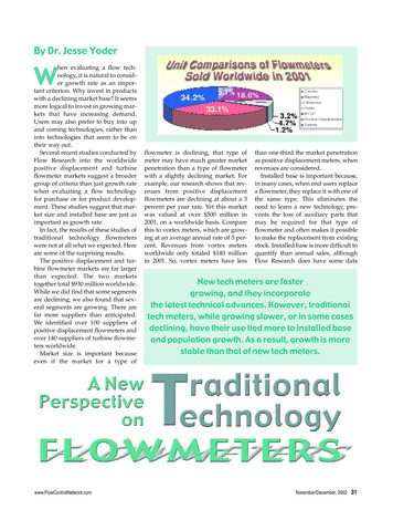
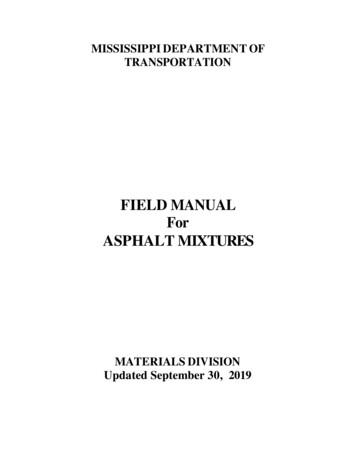
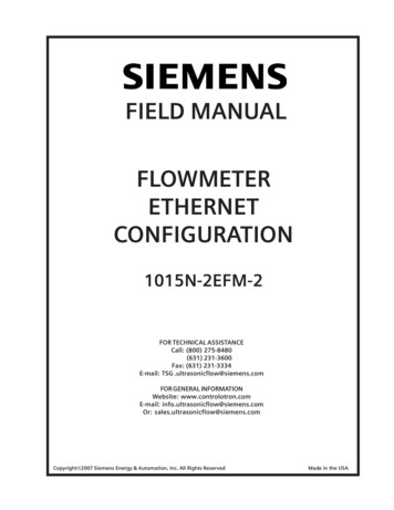
Section 11.21015N-2EFM-2CONFIGURATIONS1-4
Section 11015N-2EFM-21.2.1 DIRECT CONNECTIONIn the proceeding illustration, there are three methods of connecting a flowmeter to a datacollection station at the installation site. If there is a direct connection between the flowmeterand the station, they will reside on the same Subnet as defined by their respective Subnet Masks.The IP Address of the flowmeter must be specified by the Network Administrator. There mustexist a Network Node in-between the data collection station and the flowmeter or the electricalequivalent of a Null Modem. This is necessary since both devices will attempt to transmit on thesame wire of the cable.In a point-to-point direct connection, there exists many instability problems, especially withMicrosoft Windows. A HUB or Router is often used. If a HUB is used, care must be taken thatthe data collection station operate on the same speed as the flowmeter, which is 10MHz, or thatthe HUB have a speed translator for its downstream ports. A Router will always work betterthan a HUB by increasing stability, providing a constant IP address on the network, andperforming any necessary speed translation.If the IP Address for the flowmeter is in the WAN address range, it is strongly suggested that theSubnet Mask be left as the default for the Class of IP Address used, usually Class C. TheGateway need not be specified.If the IP Address for the flowmeter is a LAN Address, the Subnet Mask may default to theClassfull Mask, but it is always a good idea to double-check with the Network Administrator.OSI Software, for example, runs two Subnets on the same LAN and uses a non-standard NetworkMask.1.2.2 WIDE AREA NETWORKIf the flowmeter is attached to a LAN, but access to it is permitted from the WAN, there will bea NAT, Firewall, Switch or Gateway (e.g., a Router) in-between. The Network Mask is doublechecked to be correct for the LAN configuration. The IP Address is always specified. However,in this example, a Default Gateway is not optional. The Default Gateway will be the IP Addressof the closest Router. Without this information, traffic will often flow in only one direction andthe configuration will remain incomplete.1.2.3 LOCAL AREA NETWORKThis will be the most common type of installation. The IP Address will be specified as a LANaddress. The Network Mask should be double-checked to see if it’s the Classfull Default or if hasbeen configured to be something non-standard. All traffic will flow to/from one downstream portof the closest router to the collection station on another downstream port of the router.If the flowmeter and the data collection station exist on the same Subnet, no Default Gatewayneeds to be specified. If they exist on different Subnets, the Default Gateway may need to beconfigured as the IP Address of Router closest to the flowmeter.1-5
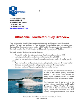
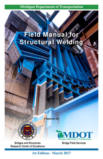
1015N-2EFM-2Section 22.FLOWMETER CONFIGURATIONThe following procedure sets up the communication parameters between the Model 1010flowmeter and the 1015N-5M. Note that the following are not the ModBus or NZ parameters.zUse the Up/Down arrows and scroll to [Meter Facilities].zWith [Meter Facilities] shown use the Right arrow to access the sub menu.zUse the Up/Down arrows and scroll to [RS-232 Setup].zUse the Right arrow to access the RS-232 setup parameters. Use the Right arrow to choose the parameters shown below. Use the Up/Down arrows to scrollto desired choice.zPress the Enter key to select.Baud Rate 9600Parity OddData Bits 7Line Feed NoNetwork ID 0 (Note: This is not the MODBUS ID.)RTS Key Time 0.22.1TABLE GENERATIONFor each flowmeter, a table nee
Controlotron is now part of: Siemens Energy & Automation, Inc. Process Instrumentation Business Unit (PI BU) CoC Ultrasonic Flow Prepared By Date Engineering Date. Table Of Contents 1015N-2EFM-2 Section 1 1. . A flowmeter may never have an IP Address which ends in 0 or 255. IP Address