Transcription
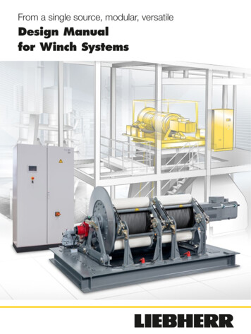
From a single source, modular, versatileDesign Manualfor Winch Systems
Contents21IntroductionPage 082Overview and performance spectrumPage 163Design basics and boundary conditionsPage 204Determination of mechanismPage 265Iteration for deviating drum speedsPage 366Determination of gear ratioPage 427Determination of motor sizePage 468Determination of switch cabinet sizePage 509Calculation of required rope lengthPage 5410Determination of drum widthPage 5811Determination of basic dimensionsPage 6612Features and optional functionsPage 7013EnquiryPage 7414Appendix (iteration tables)Page 78Design Manual for Winch Systems
Design ResultsDesign basisNomenclatureLifting loadLifting speedLifting heightNumber of fixed deflection sheaves between drum and hoist or moving partRequired service lifeNumber of winding layers on a drumNumber of parallel hoists or ropes reeved on a drumHoist reevingInstallation altitudeAmbient temperature winchAmbient temperature switch cabinetmh [t]vh[m/min]H [m]nu [-]t [h]nl [-]nr [-]nm [-]Height above sea level [m]T [ C] (min./max.)TSRA [ C] (min./max.)Design resultsNomenclatureRope drive efficiencyRope tensile forceRope speedRequired usable winding capacityLoad spectrumOperating classMechanism groupRope diameterGearbox sizeDrum diameterMax. winding diameterMean winding diameterDrum speedEquivalent service life (only if iteration required)Redefinition of operating class (only if iteration required)Redefinition of mechanism group (only if iteration required)Required gear ratio @ 1500 rpmRequired gear ratio @ 750 rpmRated motor speed 1500 or 750 rpmSelected gear ratioGearbox efficiencyMotor speedRequired mechanical drive powerMotor correction factorMotor operation categoryRequired mechanical motor powerElectric motor sizeMotor lengthMotor currentFrequency converter correction factorFrequency converter output currentSwitch cabinet sizeηs [-]FS [kN]vS [m/min]LW [m]Li [-]Ti [-]M [-]d [mm]PEG [-]DT [mm]DW max [mm]DW mean [mm]nT [rpm]tequ [h]Ti PEG [-]MPEG [-]i@1500rpm [-]i@750rpm [-]nB [rpm]i [-]ηPEG [-]nMot [rpm]PMech [kW]kM [-]S [-]PMotor [kW]KGF [-]LMot [mm]IMotor [A]kFC [-]IFC [A]SRA [-]Switch cabinet dimensions[mm]Required switch cabinet apparent powerSheave diameterRope length between winch and hoistMax. distance between upper and lower return pulley block of the hoistRequired rope lengthGroove width on the drum for one ropeDrum variantDrum widthPSRA [kW]DS [mm]LSW [m]L1 [m]LR [m]WV [mm]Tx [-]WT [mm]Winch system dimensions[mm]The input screen for the results and design basis and boundary conditionsof the winch system can also be found atwww.liebherr.com/drive-systems3Design Manual for Winch SystemsDesign basisResults of 1stcalculationIf requiredResults for iterationWSRA DSRA HSRA WWIS DWIS HWIS
Design stepsStepPageDesign basics and boundary conditions Determination of basic boundary conditions such as : Lifting load, lifting speed and lifting height Number of deflection sheaves Required service life Number of layers and number of ropes per drum Hoist reeving Calculation of the rope drive efficiency Conversion of lifting load to rope tensile force Conversion of lifting speed to rope speed Calculation of the required usable winding capacity Mechanism group according to application and required service life16Determination of mechanismDetermination of the rope, drum and max. winding diameter as well as the gearbox size based on Rope hoist Mechanism group Number of winding layers (1 to 7) Number of parallel hoists (1 or 2)26If required: iteration of the determination of the mechanism if drum speed deviates strongly from design speed of gearbox ( nT 11 rpm or nT 17 rpm )4Determination of the drum speed based on Rope speed Drum diameter Mean winding diameter36Determination of the gear ratio and calculation of the mechanical drive power based on Gearbox size Drum speed Rope tensile force Rope speed Gear efficiency42Determination of the motor size based on Mechanical drive power Installation altitude Ambient temperature range Operation category46Determination of the switch cabinet and frequency converter size and connected apparent power based on Motor current Installation altitude Mechanical drive power Ambient temperature range50Calculation of the required rope length based on Rope length between winch and hoist Hoist design Sheave diameter54Determination of the drum width based on Required usable winding capacity Rope diameter Drum diameter Number of winding layers58Determination of basic dimensions of the winch system66Features and optional functions70Design Manual for Winch Systems
Preamble and ImprintThis design manual is intended to provide a broad overview into the performance spectrum of Liebherrwinch systems. It should guide the end user through the basic design steps of a winch within the modular system of Liebherr. The usual requirements for the definition of winch systems have been taken intoaccount. Requirements not covered in this manual can of course be examined on request and customer-specific solutions can be provided.The design procedure has been broken down and is shown in the adjacent table. Depending on the result, it can be necessary to iterate the calculation steps for the definition of the boundary conditions andthe mechanism. Detailed information about the individual design steps can be found in the respectivechapter. The intermediate results of the preliminary design can be entered in the table of the expandedcover sheet.We expressly point out that only a preliminary design is possible using this manual in order to give thecustomer an impression of the required components and dimensions of the winch system. A detailedtechnical evaluation by Liebherr must always be carried out as the project progresses.We reserve the right to make changes resulting from further development of the product range.All texts, images, graphics, tables or other image representations and their arrangement are legallyprotected (Copyright Liebherr-Components AG, all rights reserved). Without express permission inwriting of Liebherr-Components AG, the contents of this design manual may neither be used for commercial purposes nor be copied, distributed, modified or made available to third parties for commercialpurposes. Some of the images shown in this design manual are subject to the copyright of third parties.Publisher:Liebherr-Components AGPostfach 222CH-5415 Nussbaumen / AGSwitzerlandTel: 41 (0) 56 296 43 00Fax: 41 (0) 56 296 43 01e-mail: components@liebherr.comwww.liebherr.comCopyright February 2019Liebherr-Components Biberach GmbH, Biberach an der RissDesign Manual for Winch Systems5
6Design Manual for Winch Systems
Contents1IntroductionPage 082Overview and performance spectrumPage 163Design basics and boundary conditionsPage 204Determination of mechanismPage 265Iteration for deviating drum speedsPage 366Determination of gear ratioPage 427Determination of motor sizePage 468Determination of switch cabinet sizePage 509Calculation of required rope lengthPage 5410Determination of drum widthPage 5811Determination of basic dimensionsPage 6612Features and optional functionsPage 7013EnquiryPage 7414Appendix (iteration tables)Page 78Design Manual for Winch Systems7
Winch systems from LiebherrLiebherr has been producing all the relevant components required for a lifting system for many yearsand now also provides complete winch systems on the market. The components are perfectly matchedin their function. This results in convincing system solutions that can be integrated into a variety of applications.8Design Manual for Winch Systems
Safe, robust, powerfulModular systemLiebherr provides customised system solutions based onstandard components for lifting applications that are characterised by scalability and simple integration and commissioning at the customer site -"plug & lift".Everything from a single sourceAll essential components of the winch systems such asdrum, planetary plug-in gear, asynchronous motor andswitch cabinet are developed and produced in-house. Withthis prerequisite, it is possible to provide a modular system inwhich the individual components are perfectly matched witheach other. The modular winch system is designed to covera wide range of customer requirements and convinces withshort time for development.Simple assemblyWinch systems from Liebherr score mainly due to their shortassembly time at the customer site. The complete winch issupplied pre-assembled on a frame, eliminating the needfor time-consuming individual on-site assembly. The switchcabinet according to the customer's requirements is mounted on the winch frame and pre-wired. Alternatively the switchcabinet will be supplied as a separate unit. The control andpower electronics are prepared in the factory according tothe "connect & use" principle.Service and SupportLiebherr Customer Service provides support as requiredwhen the winch system is installed and put into service atthe customer site. For example, when the rope needs to bewound under pre-tension or the function of the system needsto be demonstrated for final acceptance.GearboxThe gearbox is selected from Liebherr's proven productrange of planetary plug-in gearboxes (PEG). This is impressive due to a robust and at the same time compact design.Oil cooling and oil heating for the gearbox are available asoptions.Electric motorThe winches are driven via compact, air-cooled asynchronous squirrel-cage motors. These are available in the powerrange up to 250 kW and are designed for use under theharshest conditions. Efficiency is standard at Liebherr: Themotors meet the requirements of efficiency class IE2 or higher in continuous operation. In addition, the motors allow ahigh degree of spreading. This means that the motor can beoperated up to 3 times the rated speed at constant powerin partial load operation (e.g. no load running). This enablesthe end application to achieve optimum economic efficiency.Switchgear and control systemThe switchgear and the entire control system are designedaccording to the EN13849 standard. Only robust productsfrom well-known manufacturers are used for power andcontrol electronics. Optionally there is the possibility of active power regeneration. For applications with frequent loadcycles, an energy storage system based on double-layer capacitors is optionally available in order to increase the overallcost-effectiveness. The range is rounded off with an innovative controller that ensures effective and safe operation of therespective system.SafetyA secondary brake, various sensors and optional integrated slackrope detection ensure the safe operation of the winch system. Theappropriate monitoring program developed by Liebherr is shown onthe switch cabinet display. It can be transferred to the customer via aninterface to the higher-level process control system.Design Manual for Winch Systems9
Application examplesLifting equipment for machineryand plant construction10Design Manual for Winch Systems
Liebherr winch systems are configured or modified according to the customer application based onLiebherr standard components. They can be used for a wide range of tasks in the area of lifting andconveyor technology as well as in adjustment systems. Accordingly, the target industries are also varied.Examples include mechanical and plant engineering, offshore, mining and raw material industries, steelhydraulic engineering, bridge construction and the amusement sector.Loading system for lime kilnsWhen loading lime kilns, Liebherr winch systems increasethe productivity of the plants by increasing the speed up tothree times during the no-load return stroke. Reliability undercontinuous loads and high levels of dirt as well as the guarantee of operational safety are only some of the requirementsthat are met without compromise.Bridge buildingAs a restraint or pulling winch, e.g. for the construction ofsuspension bridges or for the longitudinal insertion methodof pre-assembled bridge segments, monitoring of the ropetensile force and the position ensures exact positioning andmaximum safety.Amusement RidesThe control and design of Liebherr winch systems ensurefunctional safety in every operating situation when used infree fall towers or as a hoist for roller coaster carriages.Lifting of gondolasfrom free fall towersDesign Manual for Winch Systems11
Application examplesBoom height adjustmentof ship unloadersThe adjustment of the boom using a modular Liebherr winch systemprovides our customers with the possibility of concentrating on the corecompetences and reducing the complexity of auxiliary functions. Thecontroller of the winch system ensures sensitive height adjustment ofthe boom.12Design Manual for Winch Systems
Gate control at hydro power plantsVertically operated gates of hydro power plants can be operated with winch systems as a less expensive alternative toa solution with hydraulic cylinders. If more than one winchsystem is required for the actuation of a gate, the intelligentcontrol system ensures perfect synchronisation of the ropedrives to prevent the gate from tilting in its guide.Screen cleaning system at hydro power plantsWinch systems as drives for screen cleaning systems provide our customers with the possibility of automation andthe transfer of responsibility to one source. Furthermore, it ispossible to integrate additional functions of the system intothe control of the winch system.Ship’s liftDue to the use of many identical drives, the regulation and control of the position and orientation of theship's dock are particularly important. The same applies to the force distribution. The integration of theindividual drives into a higher-level control system is already completed in the delivery condition and thusallows simple commissioning for the customer.Design Manual for Winch Systems13
Production sitesLiebherr-Components Biberach GmbHLiebherr-Components Biberach GmbH develops and produces high-performancecomponents – such as electrical machines, gearboxes, large diameter bearings, winchesand switchgear systems – both for the group of companies and for external customers.In addition, the newly established business unit "Drive System Technology" ensures theintegration of individual components into customer-specific systems. Some examples arewinch systems, electric drive systems for tracked vehicles, diesel-electric drive systems formining trucks and pitch systems for wind turbines.HeadquartersFacts and figures: Liebherr-Werk Biberach GmbH was founded in 1954(founding of Liebherr-Components Biberach GmbH in 2012) Headquarters of the business units "Drives" and "Large diameter bearings" Design and production of gearboxes, winches and large diameterbearings; assembly of winch systems Number of employees: 1,384 Factory premises: 345,657 m²Biberach factory, GermanyHeadquarters in Biberach an der Riss14Design Manual for Winch SystemsSubsidiaryFacts and figures: Establishment of the subsidiary in 2015 to expand the design andproduction capacity of electrical machines and control technology Headquarters of the business units "Electric Drives andControl Technology" and "Drive System Technology" Number of employees: 335 Factory premises: 145,657 m²Subsidiary in Biberach an der Riss
Contents1IntroductionPage 082Overview and performance spectrumPage 163Design basics and boundary conditionsPage 204Determination of mechanismPage 265Iteration for deviating drum speedsPage 366Determination of gear ratioPage 427Determination of motor sizePage 468Determination of switch cabinet sizePage 509Calculation of required rope lengthPage 5410Determination of drum widthPage 5811Determination of basic dimensionsPage 6612Features and optional functionsPage 7013EnquiryPage 7414Appendix (iteration tables)Page 78Design Manual for Winch Systems15
Overview and performance spectrumUnder the listed boundary conditions, the modular winch system covers a wide performance spectrumwith matched Liebherr standard components.Control electronicsand monitoring Control system according toEN13849 Proven and robust PLC Functional safety Automatic process data acquisitionand system monitoring (data logger) Standard module functions such asoil cooling or motor heating can beadded to the software Bus interface for higher-level controlsystemSwitch cabinet 7" display shows operating statesand errors External controls for 2 directionswith 2 speed setpoints each Power supply: 3-phase 400 V AC50 60 Hz Type of power grid: TN system Ambient temperature: -20 45 CPower electronics Proven frequency converters fromwell-known manufacturers Special control of the asynchronousmotor by the frequency converterfor exact position and speed controleven at zero speed passage Possibility of parametrisation forsetting e.g. drum speed, start andstop ramps Possibility to synchronise multiplewinch systems Optionally with regenerative unit(Active Front End) Possibility of connecting an energystorage device to cover power peaks16Design Manual for Winch Systems
Customer-specificsystem solutionsIn the case of different parameters or extended function requirements, a customer-specific solution can berealised on request in addition to the modular winch system. Liebherr provides customised development ofthe individual components as well as the control software to cover all customer needs.Secondary Brake Second safety brake with “failsafe closed” function to protect theelectric-mechanical drive trainSlack Rope Detection (optional) Activates the winch safety shut-off ifslack rope is detectedPlanetary Plug-in Gearboxes (PEG) Standard series from PEG 300 toPEG 700 Max. dynamic torque up to approx.218.000 Nm Standard gear ratios forrope speeds from 4 to 120 m/min( 4 and 120 m/s on request)Electric motor Asynchronous motors from in-housedevelopment and production Power range up to 124 kW in S1operation according to IE2; short timeup to 250 kW High spreading: up to 3 times therated speed possible Ambient temperatures from-20 to 45 C Motor brake and encoder as standardRope drum Wire rope hoist from 1 to 30 t Rope diameter from 10 to 40 mm Drum diameter from 420 to 820 mm Multilayer winding up to 7 layers Standard DIN groove for single layerwinding Special groove for multilayer windingDesign Manual for Winch Systems17
18Design Manual for Winch Systems
Contents1IntroductionPage 082Overview and performance spectrumPage 163Design basics and boundary conditionsPage 204Determination of mechanismPage 265Iteration for deviating drum speedsPage 366Determination of gear ratioPage 427Determination of motor sizePage 468Determination of switch cabinet sizePage 509Calculation of required rope lengthPage 5410Determination of drum widthPage 5811Determination of basic dimensionsPage 6612Features and optional functionsPage 7013EnquiryPage 7414Appendix (iteration tables)Page 78Design Manual for Winch Systems19
Design basisFor the rough layout of a winch system based on this manual, certain parameters and requirements ofthe winch system must be known for the calculation. If this is not yet the case, assumptions must bemade instead, which must be corrected in an iteration depending on the result of the first layout.Lifting load (mh)In addition to the maximum mass of the object to be lifted, the mass of the load handling equipment (e.g.crane hook, cross member) as well as the mass of the pulley block and the mass of the rope length,which hangs freely above the object to be lifted, must also be taken into account.Lifting speed (vh)The speed at which the object should be lifted should be taken into account.Lifting height (H)Maximum height difference by which the object should be lifted.Number of deflection sheaves (nu)Sheaves that are required for deflection of the rope between winch and pulley block.Required service life (t)The service life is defined as the sum of the time in which the mechanism is in motion (load-independent).20Design Manual for Winch Systems
Number of winding layers on the drum (nl)For large rope lengths to be wound (e.g. high hoist reeving, high lifting height), it makes sense to windmultiple layers on the drum. Advantage:High winding capacity for compact drum Disadvantage: Reduction of rope service lifeIf the number of winding layers is completely unknown, it is recommended to assume as start value onelayer per 50 m rope length to be wound, for the first calculation cycle (max. 7 layers). Please carry out aniteration of the calculation depending on the result of the drum width or the winding capacity.Number of reeved ropes per drum (nr)In the case of limited rope lengths to be wound (e.g. loading winches), it may be advisable to wind tworopes (single layer) on one drum. Advantage:Smaller rope diameter Disadvantage: Limited winding capacityLarge drum widthHoist reeving (nm) and number of deflection sheaves (nu)The reeving of a pulley block corresponds to the number of rope strands in a pulley block on which themoving object is attached (see figure below). Increasing these is particularly advisable if the lifting loadis high at moderate lifting speeds. Advantage:Reduction of the size of the rope diameter, drum diameter and gearbox Disadvantage: Reduction of rope service lifeRequires higher winding capacity and rope length123Winch41WinchLifting weightNumber of deflection sheaves nu 2; hoist reeving nm 4Lifting weightNumber of deflection sheaves nu 2; hoist reeving nm 1Design Manual for Winch Systems21
Design basics and boundary conditionsCalculation of rope drive efficiency (ηs)ηs nηr u n1 – ηr mnm (1 – ηr )(according to DIN 15020-1)ηr [-]:Efficiency of one rope sheave with ηr 0.96 for friction bearing and ηr 0.98 for roller bearingnu [-]:Number of fixed deflection sheaves between drum and hoist or moving partnm [-]:Hoist reevingCalculation of rope tensile force (FS)Fs mh 9,81mS2 1nm nr η sFs [kN]: Rope tensile forcemh [t]:Lifting load that the winch should be loaded with equipmentnm [-]:Hoist reevingnr [-]:Number of ropes per drumηs [-]:Pulley block efficiency123FsWinchLifting weight22Design Manual for Winch Systems4
Calculation of required rope speed (vs)vs vh nmvs [m/min]: Rope speedvh [m/min]: Lifting speednm [-]: Hoist reevingCalculation of required usable winding capacity (LW)LW H nmLW [m]: Required usable winding capacity per ropeH[m]: Lifting heightnm [-]: Hoist reevingDetermination of the mechanism group (M)The classification of the application into the appropriate mechanism group depends on the load spectrum (Li) as well as onthe operating class (Ti) that takes account of the service life accordingly. The service life is defined as the sum of the time inwhich the mechanism is in motion (load-independent).Operating class* Ti T1T2T3T4T5T6T7T8Required service life [h] Up to 400Up to 800Up to 1,600Up to 3,200Up to 6,300Up to 12,500Up to 25,000Up to 50,000Load spectrum* LiMechanism group* M T1T2T3T4T5T6T7T8L1Maximum load is the exception, otherwise usually low loadsM1M1M2M3M4M5M6M7L2About the same proportions of low, medium and high loads,e.g. many types of cranesM1M2M3M4M5M6M7M8L3Loads are frequently close to the maximum load, e.g. loadingwinches in plant construction: maximum load during lifting /no load run during loweringM2M3M4M5M6M7M8M9L4Always maximum load, e.g. winch for adjusting the belttension on belt conveyors; gate actuationM3M4M5M6M7M8M9* FEM - Federation Européenne de la Manutention (European Materials Handling Federation) Section I, Rules for the design of hoisting appliances, 3rd edition 1998Design Manual for Winch Systems23
24Design Manual for Winch Systems
Contents1IntroductionPage 082Overview and performance spectrumPage 163Design basics and boundary conditionsPage 204Determination of mechanismPage 265Iteration for deviating drum speedsPage 366Determination of gear ratioPage 427Determination of motor sizePage 468Determination of switch cabinet sizePage 509Calculation of required rope lengthPage 5410Determination of drum widthPage 5811Determination of basic dimensionsPage 6612Features and optional functionsPage 7013EnquiryPage 7414Appendix (iteration tables)Page 78Design Manual for Winch Systems25
Determination of mechanismUsing the parameters defined in the "Design basics and boundary conditions" chapter, such as ropetensile force (FS), mechanism group (M), number of ropes per drum (nr) and the number of layers of awinding (nl), the mechanical part of the winch will be defined. The rope diameter (d), the gearbox size(PEG), the drum diameter (DT ) and the maximum winding diameter (DW max) are determined using theselection tables on the following pages.The calculation of the gearbox size and the drum diameter is relatively complex. On the one hand, a largenumber of parameters need to be taken into account, on the other hand, several iterations of the calculation can be necessary. For example, the load torque of the gearbox depends, amongst other things,on the drum diameter; which in turn depends, among other things, on the gearbox size. The results ofthe iteration are shown in the selection tables on the following pages and have been calculated on thebasis of the following: Rotation-free steel cable with the strength of 1960 N/mm² and a cross section related minimum breaking force of 1.05 kN/mm². Rope breakage safety (SB) and minimum DT/d ratio (h1) according to the table below. This is based onthe ISO 16625 standard. However, based on experience, the values for multi-layer windings are limited downwardly, deviating from the standard, in order to guarantee long service life despite increasedrope wear.Rope breakage safetySB Mechanism group Mone layerDT/d ratioh1multi-layerone 2.4M8992525M94.520M51820 The influence of the secondary brake is taken into account for the structural design of the gearbox.The maximum static load case is defined by the application of the secondary brake during lifting ofthe load.Depending on the number of layers and number of ropes per drum, the corresponding tables can befound on the following pages:1 layer, 1 rope:1 layer, 2 ropes:2 layers, 1 rope:3 layers, 1 rope:4 layers, 1 rope:5 layers, 1 rope:6 layers, 1 rope:7 layers, 1 rope:Page: 27Page: 28Page: 29Page: 30Page: 31Page: 32Page: 33Page: 34Please do not hesitate to contact us if your requirements are not covered by the selection tables.26Design Manual for Winch Systems
1 layer, 1 rope1 layer, 1 rope Max. winding diameterDW max [mm]Rope diameter d[mm]Gearbox size PEG[mm]Drum diameterDT [mm]Max. winding diameterDW max [mm]Rope diameter d[mm]Gearbox size PEG[mm]Drum diameterDT [mm]Max. winding diameterDW max 0Drum diameterDT [mm]420420Gearbox size PEG[mm]420300Rope diameter d[mm]30010Drum diameterDT [mm]1011.2Gearbox size PEG[mm]10Rope diameter d[mm]Drum diameterDT [mm]M9Gearbox size PEG[mm]M8Rope diameter d[mm]M7Max. winding diameterDW max [mm]M6Max. winding diameterDW max [mm]Rope tensile force FS 075028040650750750Continued on page 36Design Manual for Winch Systems27
1 layer, 2 ropes1 layer, 2 ropes Drum diameterDT [mm]Max. winding diameterDW max [mm]Rope diameter d[mm]Gearbox size PEG[mm]Drum diameterDT [mm]Max. winding diameterDW max [mm]420420420Drum diameterDT [mm]420300Gearbox size PEG[mm]30010Rope diameter d[mm]10420Drum diameterDT [mm]420420Gearbox size PEG[mm]420300Rope diameter d[mm]30010Drum diameterDT [mm]10Gearbox size PEG[mm]89Rope diameter d[mm]Gearbox size PEG[mm]M9Rope diameter d[mm]M8Max. winding diameterDW max [mm]M7Max. winding diameterDW max [mm]M6Max. winding diameterDW max [mm]Rope tensile force FS 007507502855075075071204505
Examples include mechanical and plant engineering, offshore, mining and raw material industries, steel hydraulic engineering, bridge construction and the amusement sector. Loading system for lime kilns When loading lime kilns, Liebherr winch systems increase the productivity of the plants by increasing the speed up to